FENDT Vario 700 Series User manual

Fendt Vario 700, 800, and 900 Series
SmarTrax™ MD Installation Manual
P/N 016-5030-043 Rev A 09/15 E22761
Copyright 2014, 2015

While every effort has been made to ensure the accuracy of this document,
Raven Industries assumes no responsibility for omissions and errors. Nor is any
liability assumed for damages resulting from the use of information contained
herein.
Raven Industries shall not be responsible or liable for incidental or consequential
damages or a loss of anticipated benefits or profits, work stoppage or loss, or
impairment of data arising out of the use, or inability to use, this system or any of
its components. Raven Industries shall not be held responsible for any
modifications or repairs made outside our facilities, nor damages resulting from
inadequate maintenance of this system.
As with all wireless and satellite signals, several factors may affect the availability
and accuracy of wireless and satellite navigation and correction services (e.g.
GPS, GNSS, SBAS, etc.). Therefore, Raven Industries cannot guarantee the
accuracy, integrity, continuity, or availability of these services and cannot
guarantee the ability to use Raven systems, or products used as components of
systems, which rely upon the reception of these signals or availability of these
services. Raven Industries accepts no responsibility for the use of any of these
signals or services for other than the stated purpose.
Disclaimer
©Raven Industries, Inc. 2014

Table of Contents
Manual No. 016-5030-043 Rev. A i
Chapter 1 Important Safety Information................................................. 1
Electrical Safety ........................................................................................................................ 2
Chapter 2 Introduction............................................................................. 3
Preparing for Installation ........................................................................................................... 4
Recommendations .............................................................................................................. 4
Point of Reference ............................................................................................................... 4
Updates ..................................................................................................................................... 4
Kit Contents ............................................................................................................................... 5
Chapter 3 Mechanical Drive Installation ................................................ 9
Remove the Steering Wheel ..................................................................................................... 9
Install the Anti-Rotation Bracket .............................................................................................. 11
Install the Spline and Ring Gear Assemblies .......................................................................... 13
Reinstall the Steering Wheel ................................................................................................... 14
Install the Mechanical Drive ....................................................................................................15
Chapter 4 Node and Wiring Installation ............................................... 19
Install the SmarTrax MD Node ................................................................................................ 19
Node Mounting Locations .................................................................................................. 19
Mount the SmarTrax MD Node .......................................................................................... 20
Install the Foot Switch ............................................................................................................. 21
Install the Node Harness ......................................................................................................... 22
Install the Chassis Cable - SmarTrax MD-Only Systems (If Applicable) ................................. 23
Connect SmarTrax MD to an Existing Chassis Cable (If Applicable) ...................................... 24

Table of Contents
ii Fendt Vario 700, 800, and 900 Series SmarTrax™ MD Installation Manual

CHAPTER
1
Manual No. 016-5030-043 Rev. A 1
C hapt er 1
Important Safety
Information
Read this manual and the operation and safety instructions included with your implement and/or controller
carefully before installing the SmarTrax™ MD system.
•Follow all safety information presented within this manual.
•If you require assistance with any portion of the installation or service of your Raven equipment, contact
your local Raven dealer for support.
•Follow all safety labels affixed to the SmarTrax MD system components. Be sure to keep safety labels in
good condition and replace any missing or damaged labels. To obtain replacements for missing or damaged
safety labels, contact your local Raven dealer.
When operating the machine after installing SmarTrax MD, observe the following safety measures:
•Be alert and aware of surroundings.
•Do not operate SmarTrax MD or any agricultural equipment while under the influence of alcohol or an illegal
substance.
•Remain in the operator’s position in the machine at all times when SmarTrax MD is engaged.
•Disable SmarTrax MD when exiting the operator’s seat and machine.
•Do not drive the machine with SmarTrax MD enabled on any public road.
•Determine and remain a safe working distance from other individuals. The operator is responsible for
disabling SmarTrax MD when the safe working distance has diminished.
•Ensure SmarTrax MD is disabled prior to starting any maintenance work on SmarTrax MD or the machine.
•The machine must remain stationary and switched off during SmarTrax MD installation or maintenance.
NOTICE
WARNING

Chapter 1
2Fendt Vario 700, 800, and 900 Series SmarTrax™ MD Installation Manual
Electrical Safety
•Always verify that the power leads are connected to the correct polarity as marked. Reversing the power
leads could cause severe damage to the equipment.
•Ensure that the power cable is the last cable to be connected.
CAUTION

CHAPTER
2
Manual No. 016-5030-043 Rev. A 3
C hapt er 2
Introduction
Congratulations on your purchase of the SmarTrax™ MD system!
SmarTrax MD-assisted steering takes the stress out of driving and makes it quick and easy for you to improve
your operating efficiency and performance. SmarTrax MD is compatible with Cruizer II™ and Cruizer II™ RTK,
Envizio Pro™, Envizio Pro®, Envizio Pro XL™, and Viper Pro™ systems.
The following instructions are designed to assist with the proper installation of the SmarTrax MD system. Refer
to the SmarTrax MD Calibration & Operation Manual (P/N 016-5030-020) for assistance with calibrating the
software and using the SmarTrax MD system.
This manual applies to the following machines:
MAKE: Fendt
MODEL: Vario 700 Series - 712, 714, 716, 718, 720, 722, and 724
Vario 800 Series - 818, 820, 822, 824, 826, and 828
Vario 900 Series - 924, 927, 930, 933, 936, and 939
FIGURE 1. Fendt Vario 828

Chapter 2
4Fendt Vario 700, 800, and 900 Series SmarTrax™ MD Installation Manual
Preparing for Installation
Before installing the SmarTrax MD system, park the machine where the ground is level, clean, and dry. Turn off
the machine and leave it turned off for the duration of the installation process.
During the installation process, follow good safety practices. Be sure to carefully read the instructions in this
manual as you complete the installation process.
Recommendations
Raven Industries recommends the following best practices when installing or operating the SmarTrax MD
system for the first time, at the start of the season, or when moving the SmarTrax MD system to another
machine:
•Use part numbers to identify the parts.
•Do not remove the plastic wrap from a part until it is necessary for installation.
•Do not remove plastic caps from a part until it is necessary for installation.
Point of Reference
The instructions in this manual assume that you are standing behind the machine, looking toward the cab.
Updates
Software and manual updates are available on the Raven Applied Technology website:
http://www.ravenhelp.com
At Raven Industries, we strive to make your experience with our products as rewarding as
possible. One way to improve this experience is to provide us with feedback on this manual.
Your feedback will help shape the future of our product documentation and the overall service
we provide. We appreciate the opportunity to see ourselves as our customers see us and are
eager to gather ideas on how we have been helping or how we can do better.
To serve you best, please send an email with the following information to
-Fendt Vario 700, 800, and 900 Series SmarTrax™ MD Installation Manual
-Manual No. 016-5030-043 Rev. A
-Any comments or feedback (include chapter or page numbers if applicable).
-Let us know how long have you been using this or other Raven products.
We will not share your email or any information you provide with anyone else. Your feedback
is valued and extremely important to us.
Thank you for your time.

Manual No. 016-5030-043 Rev. A 5
Introduction
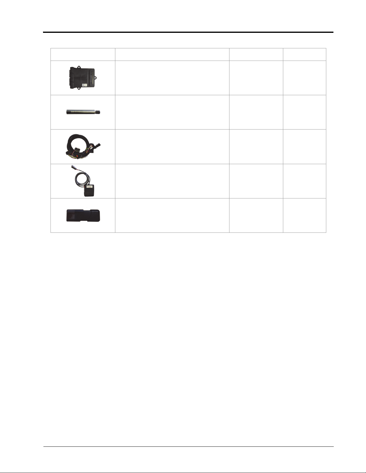
Kit Contents
This section contains a list of the components that are included in the SmarTrax MD kit. Before beginning the
system installation, compare the items in the kit with the components on this list. If you have questions about
the kit, contact your Raven dealer.
TABLE 1. SmarTrax MD Installation Kit (P/N 117-5030-043)
Picture Item Description Part Number Qty.
Not Pictured Manual - Fendt 700, 800, and 900 Series
SmarTrax MD Installation 016-5030-043 1
Assembly - Ring Gear 063-4001-011 1
Assembly - Spline Adapter 063-4001-022 1
Trim - Ring Gear Protective 019-0159-590 1
Bracket - Node Mounting 107-0172-084 1
Bracket - Angle Mounting 107-0172-270 1
Bracket - Collar Weldment 116-0159-751 1
Bearing - 1/2” Plastic Flanged 325-0000-036 1
Screw - #10-16 x 3/4” Zinc Self-Tapping 310-1002-073 4

Chapter 2
6Fendt Vario 700, 800, and 900 Series SmarTrax™ MD Installation Manual
Bolt - #10-24 x 3/4” UNC Zinc Carriage 311-0069-082 2
Bolt - 5/16”-18 x 3/4” Grade 2 Carriage 311-0069-111 2
Nut - 3/8”-16 Zinc Flanged Lock 312-1001-167 3
Nut - 5/16”-18 Zinc Flanged Lock 312-1001-184 2
Nut - #10-24 Wing 312-3000-013 2
Washer - 0.265” ID x 0.505” OD x 0.060”
Thick 313-2300-120 4
Tape - 3” Double-Sided 332-0000-019 6
TABLE 2. SmarTrax MD Controller Kit (P/N 117-5030-020)
Picture Item Description Part Number Qty.
Not Pictured Manual - SmarTrax MD Calibration &
Operation 016-5030-020 1
Not Pictured Sheet - Field Computer Minimum Software
Installation 016-5030-023 1
Assembly - SmarTrax MD Mechanical Drive
Unit 063-4001-010 1
TABLE 1. SmarTrax MD Installation Kit (P/N 117-5030-043)
Picture Item Description Part Number Qty.
Manual No. 016-5030-043 Rev. A 7
Introduction
Node - SmarTrax MD 063-4001-013 1
Pin - Anti-Rotation 107-4001-004 1
Cable - SmarTrax MD Node Harness 115-4001-157 1
Switch - Foot 063-0173-593 1
Drive - USB Flash 063-4001-020 1
TABLE 2. SmarTrax MD Controller Kit (P/N 117-5030-020)
Picture Item Description Part Number Qty.

Chapter 2
8Fendt Vario 700, 800, and 900 Series SmarTrax™ MD Installation Manual
CHAPTER
3
Manual No. 016-5030-043 Rev. A 9
C hapt er 3
Mechanical Drive
Installation
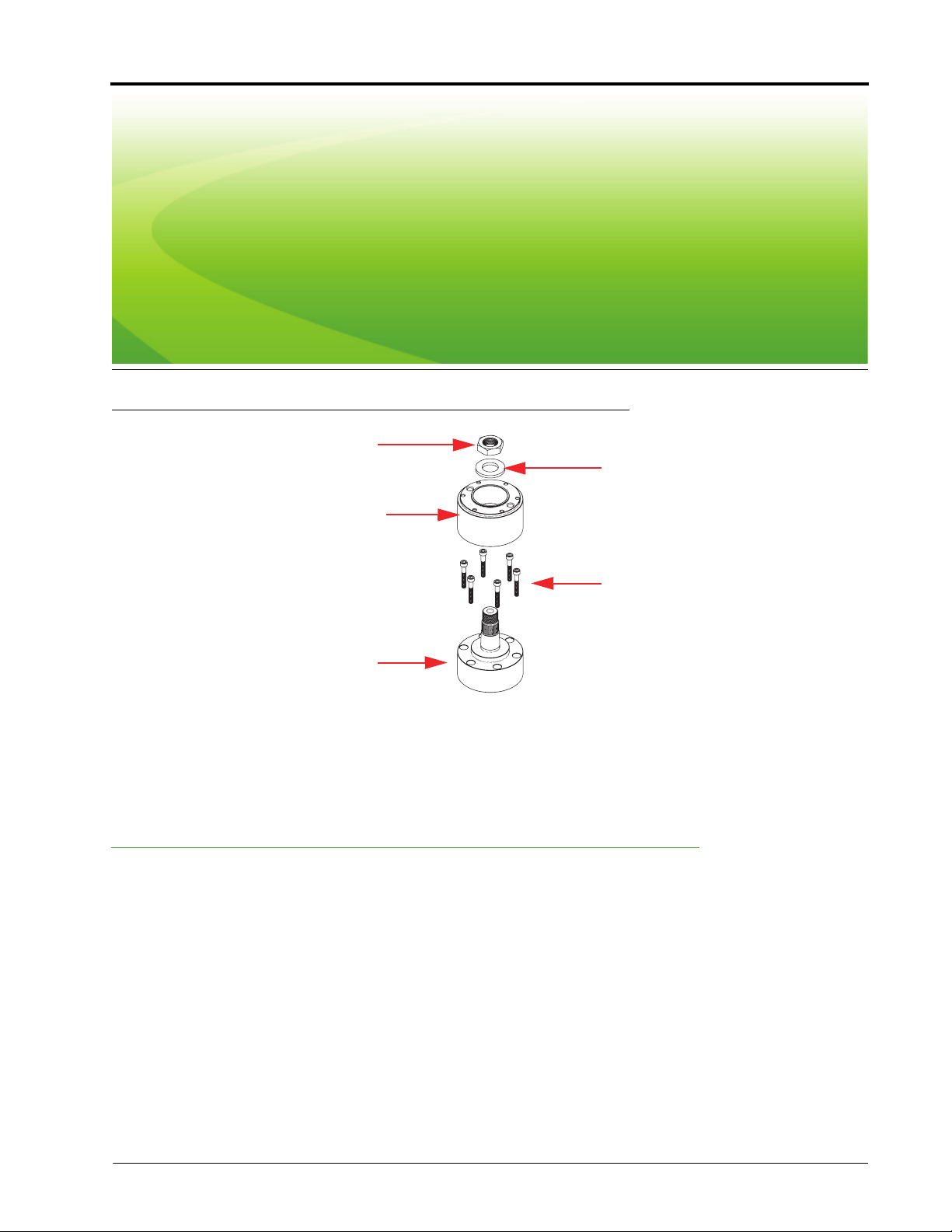
FIGURE 1. Spline Assembly Disassembled
1. Locate the 20 mm x 36 tooth spline adapter assembly (P/N 063-4001-022).
2. Disassemble the spine adapter assembly as shown in Figure 1 above.
Remove the Steering Wheel
Note: The steps in this section require use of a steering wheel puller (not supplied). For questions on the
proper procedure for removing the steering wheel, contact your local equipment dealer.
Nut
Washer
Female Spline
Adapter
Bolts
Male Spline
Adapter

Chapter 3
10 Fendt Vario 700, 800, and 900 Series SmarTrax™ MD Installation Manual
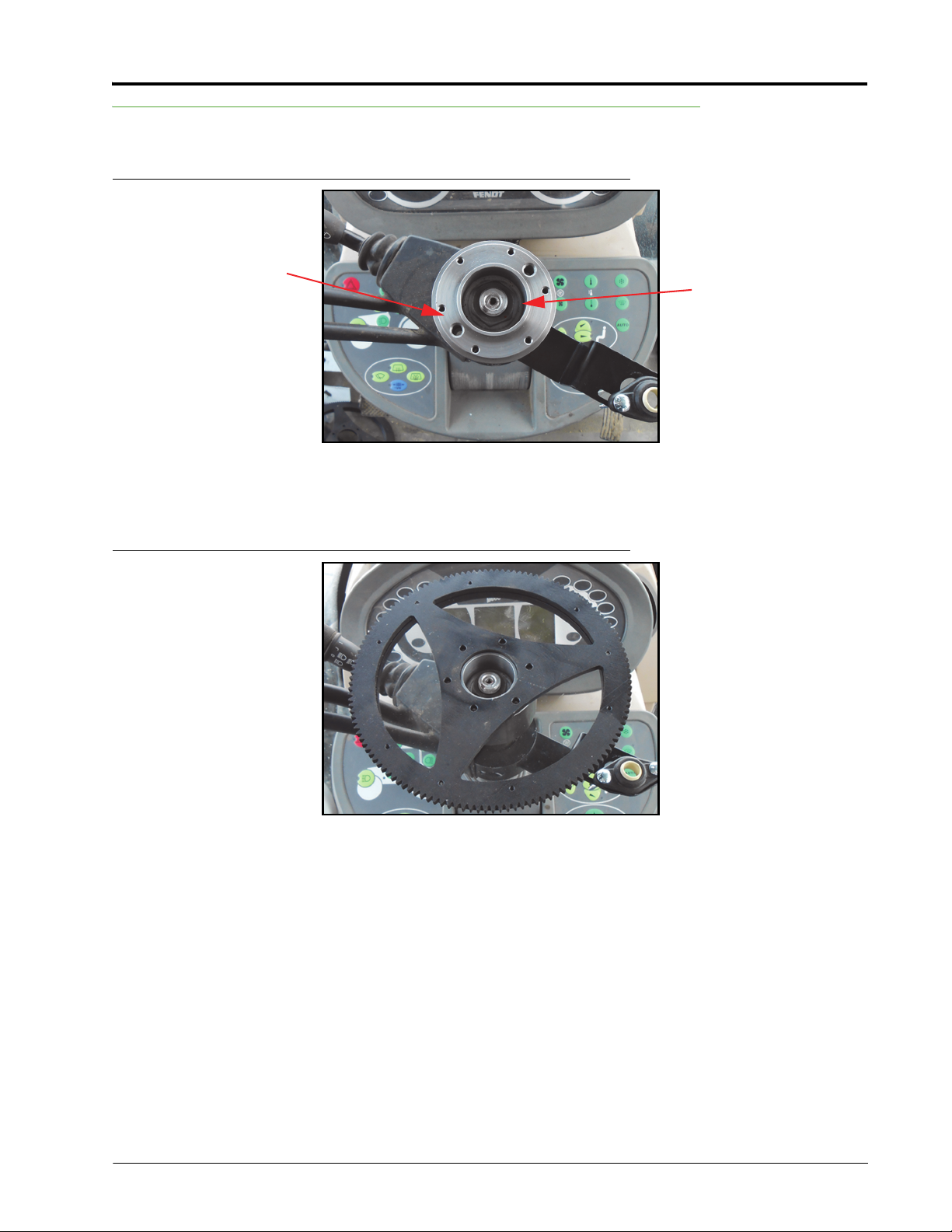
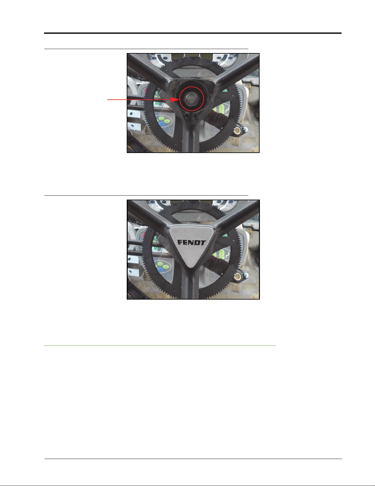
FIGURE 2. Steering Wheel Cap
1. Remove the cap from the center of the steering wheel.
FIGURE 3. Machine’s Steering Wheel Nut
2. Remove the nut used to secure the steering wheel to the steering column.
FIGURE 4. Steering Wheel Removed
3. Using the steering wheel puller, remove the steering wheel from the steering column.
Steering Wheel Nut

Manual No. 016-5030-043 Rev. A 11
Mechanical Drive Installation
Install the Anti-Rotation Bracket
FIGURE 5. Steering Column Cover
1. Remove the control arm cover.
Note: Keep the control arm cover for future use.
FIGURE 6. Bolt Removal
2. Remove the bolts used to secure the control clamp to the steering column.
3. Remove the control clamp.
Note: Keep the control clamp for future use.

Chapter 3
12 Fendt Vario 700, 800, and 900 Series SmarTrax™ MD Installation Manual
FIGURE 7. Anti-Rotation Bracket Installed
4. Clamp the collar weldment bracket (P/N 116-0159-751) around the steering column and secure it using the
machine’s bolts that were removed in step 2.
FIGURE 8. Flanged Bearing Installed on Bracket
5. Install the 1/2” plastic flanged bearing (P/N 325-0000-036) on the end of the collar weldment bracket using
two #10-24 x 3/4” carriage bolts (P/N 311-0069-082) and two #10-24 wing nuts (P/N 312-3000-013).
Collar Weldment
Bracket
(P/N 116-0159-738)
#10-24 x 3/4” UNC
Carriage Bolts
(P/N 311-0069-082)
1/2” Plastic
Flanged Bearing
(P/N 325-0000-036)
#10-24 Wing Nuts
(P/N 312-3000-013)
Manual No. 016-5030-043 Rev. A 13
Mechanical Drive Installation
Install the Spline and Ring Gear Assemblies
FIGURE 9. Female Spline Adapter Installed on Steering Column
1. Install the female spline adapter on the machine’s steering column stem.
2. Install the machine’s steering wheel nut that was removed during the steering wheel removal.
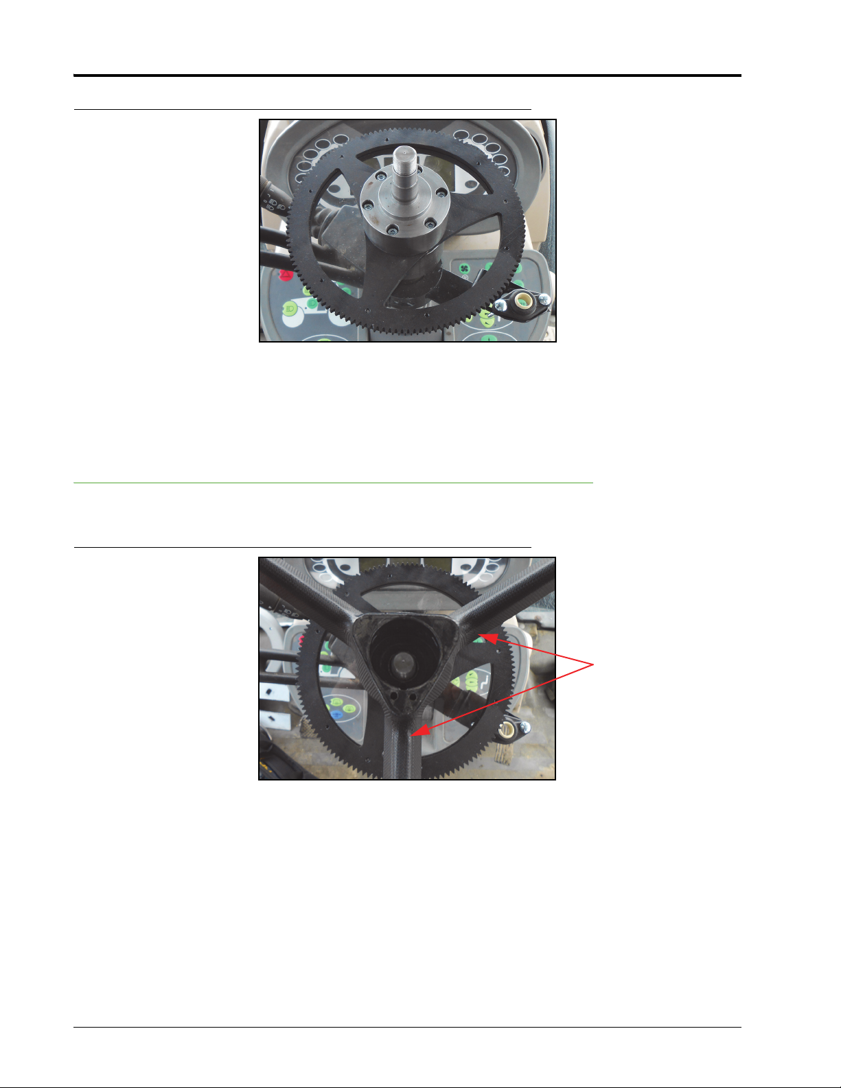
FIGURE 10. Ring Gear Installed
3. Place the ring gear (P/N 063-4001-011) over the female spline adapter with the V-ring facing down and the
holes in the ring gear aligned with the holes in the spline adapter.
Female Spline
Installed Machine’s Steering
Wheel Nut
Chapter 3
14 Fendt Vario 700, 800, and 900 Series SmarTrax™ MD Installation Manual
FIGURE 11. Male Spline Adapter Assembly Installed
4. Align the bolt holes in the male spline adapter with the holes in the ring gear assembly.
5. Install and tighten the spline assembly bolts to secure the male spline adapter and ring gear to the female
spline adapter.
Reinstall the Steering Wheel
FIGURE 12. Steering Wheel Placement
1. Align the spokes of the steering wheel with the spokes on the installed ring gear.
Steering Wheel
Spokes Aligned with
Ring Gear Assembly
Spokes
Manual No. 016-5030-043 Rev. A 15
Mechanical Drive Installation
FIGURE 13. Washer and Nut Installed
2. Install the steering wheel on the male spline adapter.
3. Reinstall the machine’s nut on the protruding male spline adapter.
FIGURE 14. Steering Wheel Cap Reinstalled
4. Replace the steering wheel cap.
Install the Mechanical Drive
Note: Depending on the machine’s configuration, it may be necessary to install the anti-rotation pin in the
mechanical drive’s casing after the mechanical drive is installed instead of before as indicated in
the instructions below.
Nut and Washer from
Spline Assembly
Installed
Chapter 3
16 Fendt Vario 700, 800, and 900 Series SmarTrax™ MD Installation Manual
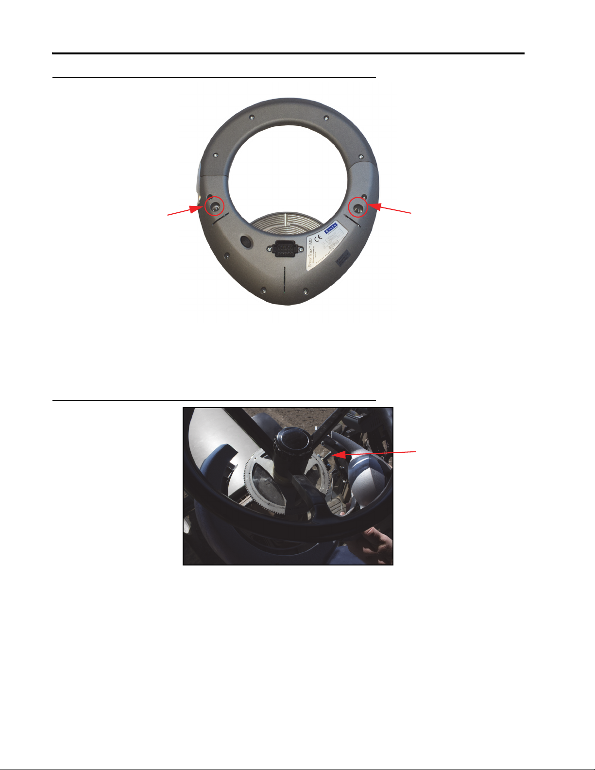
FIGURE 15. Anti-Rotation Pin Installation Locations
1. Determine the anti-rotation pin (P/N 107-4001-004) installation location on the mechanical drive (P/N 063-
4001-010) based on the anti-rotation bracket installation location.
2. Screw the anti-rotation pin into the mechanical drive’s casing.
FIGURE 16. Anti-Rotation Pin Installed in Bracket Assembly
3. Insert the anti-rotation pin into the installed flanged bearing (P/N 325-0000-036) on the anti-rotation bracket
assembly.
Anti-Rotation Brackets
Installed on Right Side of
Steering Column
Anti-Rotation Brackets
Installed on Left Side of
Steering Column
Anti-Rotation Pin Inserted
into Anti-Rotation Bracket
Assembly
This manual suits for next models
21
Table of contents
Other FENDT Tractor manuals

FENDT
FENDT 1149MT User manual

FENDT
FENDT 916 Vario User manual

FENDT
FENDT Vario MT 938 User manual

FENDT
FENDT 900 Vario Gen6 Series User manual

FENDT
FENDT New Leader NL5258G5 User manual

FENDT
FENDT Vario 800 Series User manual

FENDT
FENDT 500 Vario S4 User manual

FENDT
FENDT 916 Vario User manual

FENDT
FENDT Vario 900 Series User manual

FENDT
FENDT 1149MT User manual


