Fenix Watts V25 PLUG-IN Operating and maintenance instructions

Rychlá instalační příručka (CZ)
Watts V25 - PLUG-IN 1x
•
•
•
•
Zapnutí/vypnutí zásuvky ON/OFF
Párování zásuvky s Termostatem V22, V24 WIFI
Párování zásuvky s přijímačem (V23 - V26 master)
Reset zásuvky do továrního nastavení
1x
1 sec
2-10 sec
2-10 sec
10+ sec
LED se rozsvítí MODŘE
LED bliká ČERVENÁ a ZELENÁ
LED bliká MODRÁ a ZELENÁ
LED zabliká ZELENĚ a potom 1x blikne
INSTALAČNÍ
MANUAL
1. Popis
- V25 - bezdrátový zásuvkový přijímač navržený speciálně pro regulaci elektrických
topných žebříků, panelů, v kombinaci s bezdrátovým termostatem typu V22.
- Termostat + Přijímač - dvojice může být řízena centrální jednotkou V24 WIFI, čímž
se zajistí plné ovládání topného systému z jednoho místa.
- Přijímač V25 může být používán jako závislá jednotka přijímače V23.
- Možnost používat přijímač V25 jako časovač pro zapnutí/vypnutí v kombinaci s
centrální jednotkou V24 WIFI.
Obsah balení
OVLÁDACÍ FUNKCE Z POZICE VYPNUTÉ ZÁSUVKY
VSTUP
VÝSTUP
LED
TLÁČÍTKO NAPÁJENÍ
ČERVENÁ, ZELENÁ, MODRÁ
Mezi párováním zásuvky s termostatem a přijímačem se přepíná zmáčknutím blikajícího ovládacího tlačítka
na zásuvce.
Mezi párováním zásuvky s termostatem a přijímačem se přepíná zmáčknutím blikajícího ovládacího tlačítka
na zásuvce.
•Časovač (přednastavená hodnota 2h) 2-10 sec LED bliká MODŘE
OVLÁDACÍ FUNKCE Z POZICE ZÁSUVKY ZAPNUTÉ
Pro zaručení optimálního příjmu instalujte a zapojte přijímač dle následujících pokynů:
- Přijímač musí být umístěn ve vzdálenosti minimálně 50 cm od veškerých jiných elektrických a bezdrátových zařízení jako je GSM, Wi-Fi router.
- Zapojte přijímač do zásuvky
Pro správnou inicializaci RF je nutné dodržet následující postup.
Kombinace 1: Přijímač + termostat RF
1. Přijímač V25 musí být přepnut na VYPNUTO stisknutím tlačítka ZAPNUTO/VYPNUTO.
2. Přijímač přepněte do režimu RF init stisknutím tlačítka RF po dobu 2-10 vteřin.
3. RF LED bliká červeno zeleně - přijímač je v režimu konfigurace rádiové komunikace a čeká na konfigurační příkaz termostatu.
4. Postupujte dle návodu k termostatu - režim termostatu “RF Init”.
5. Vypnutí RF LED přijímače a vystoupení termostatu z režimu RF init signalizuje správné spárování obou prvků.
Kombinace 2: Přijímač + RF termostat + centrální jednotka RF
1. Proveďte pokyny pro spárování s termostatem uvedené v části „Kombinace 1“.
2. Přijímač přepněte do režimu RF init stisknutím tlačítka RF po dobu 2-10 vteřin.
3. RF LED bliká červeno zeleně - přijímač je v režimu konfigurace rádiové komunikace a čeká na konfigurační příkaz centrální jednotky.
4. Postupujte dle návodu k centrální jednotce - režim spárování „RF Init“.
5. RF LED přijímače se VYPNE a centrální jednotka zobrazí zprávu, že proběhlo správné spárování obou prvků
TECHNICKÁ CHARAKTERISTIKA
N898_R00 (22.03.2023)
K dálkovému ovládání této zásuvky budete
potřebovat centrální jednotku V24 a mobilní
aplikaci Fenix V24 WIFI. S tímto zapojením je
kompatibilní pouze modulární systém Fenix
V24.
Chytrá bezdrátová zásuvka

www.fenixgroup.cz
Fenix Trading s.r.o., Slezská 2790 01 Jeseník, Czech republic
+420 584 495 111
Kombinace 3: Přijímač + Termostat RF + Centrální jednotka RF + závislý přijímač/přijímače
1. Proveďte pokyny pro spárování s termostatem a centrální jednotkou uvedené v části „Kombinace 2“.
2. Hlavní přijímač (přijímač spárovaný s termostatem a centrální jednotkou) přepněte do režimu přijímače RF init stisknutím tlačítka RF po dobu 10 vteřin (V23 nebo
V26 master).
3. Svítí zelená/červená RF LED - přijímač je v režimu konfigurace rádiové komunikace a čeká na konfigurační příkaz závislého přijímače.
4. Přepněte závislý přijímač V25 (slave) do režimu RF init stisknutím tlačítka RF po dobu 2-10 vteřin a přepněte dalším stisknutím tlačítka mód do režimu přidání
přijímače (bliká modro zelené světlo).
5. RF LED hlavního a závislého přijímače se VYPNE, což znamená správné spárování obou prvků.
6. Na hlavní přijímač můžete napojit až 3 závislé přijímače, pro každý závislý přijímač zopakujte kroky 2 až 5.
Poznámka:
- Závislý přijímač V25 bude pracovat podle hlavního přijímače.
- Pouze přijímač V25 může být připojen jako závislá jednotka (max. 3 závislé jednotky).
Kombinace 4: Přijímač + Centrální jednotka
1. Přijímač přepněte do režimu RF init stisknutím tlačítka RF po dobu 2-10 vteřin.
2. RF LED bliká červeno zeleně - přijímač je v režimu rádiové konfigurace a očekává příkaz konfigurace centrální jednotky.
3. Postupujte dle návodu k centrální jednotce - režim spárování „RF Init“.
4. RF LED přijímače VYPNE a centrální jednotka zobrazí zprávu, že obě jednotky jsou správně spárovány.
Poznámka 1:
- Tímto způsobem bude přijímač V25 pracovat v režimu Časovač, budete mít možnost vytvořit týdenní program ZAPNUTO/VYPNUTO.
- V této konfiguraci můžete přidat 3 závislé jednotky V25.
Poznámka 2:
V případě instalace s termostatem V22 a ztrátou RF komunikace (RF Alarm) přijímač po 2 hodinách přeruší napájení a začne blikat zeleně, aby
signalizoval ztrátu signálu.
KOMBINACE 1 :
KOMBINACE 2 :
KOMBINACE 3 :
KOMBINACE 4 :
Provozní teplota
Přeprava a skladování
Teplotní pojistka
0°C 40°C
-10°C až +50°C
Když > 85 °C (po ochladnutí pod 65°C)
Napájení 90- 230VAC 50Hz (with European plug socket)
Elektrická ochrana Třída II - IP20
Výstup
Maximální zátěž
Relay 10Amps
250VAC 50Hz
Radiová frekvence a
Přijímací vzdálenost RF
868MHz < 10mW (Bidirectional communication)
100m in open space
30m in residential environment
Directive 2001/95/EC on General Products Safety Low voltage directive
2006/95/EEC Radio Equipment Directive 1995/5/EC-2014/53/EU ROHS
Directive 2011/65/EC The full text of the EU declaration of conformity is available
on wattswater.eu
Produkt komfirmovaný na
Třída
Příspěvek
UE 811/2013 and 2010/30/UE
IV
2%
Normy a homologace:
Váš termostat byl navržen v souladu
s následujícími normami a jinými normativními dokumenty
Popisy a fotografie obsažené v tomto dokumentu slouží pouze jako příklad a ilustrace. Fenix si vyhrazuje právo provádět jakákoli technická a designová vylepšení svých produktů bez
předchozího upozornění. Společnost Fenix tímto protestuje proti jakékoli podmínce, která se liší od podmínek společnosti Fenix nebo je obsažená v jakékoli komunikaci a v jakékoli formě,
pokud to není dohodnuto písemně a podepsáno zodpovědnou osobou společnosti Fenix.
MASTER SLAVE (max.3x)
Rychlá instalační příručka (CZ)

Quick Installation Manual (ENG)
Watts V25 - PLUG-IN 1x 1x
INSTALLATION
MANUAL
1. Presentation
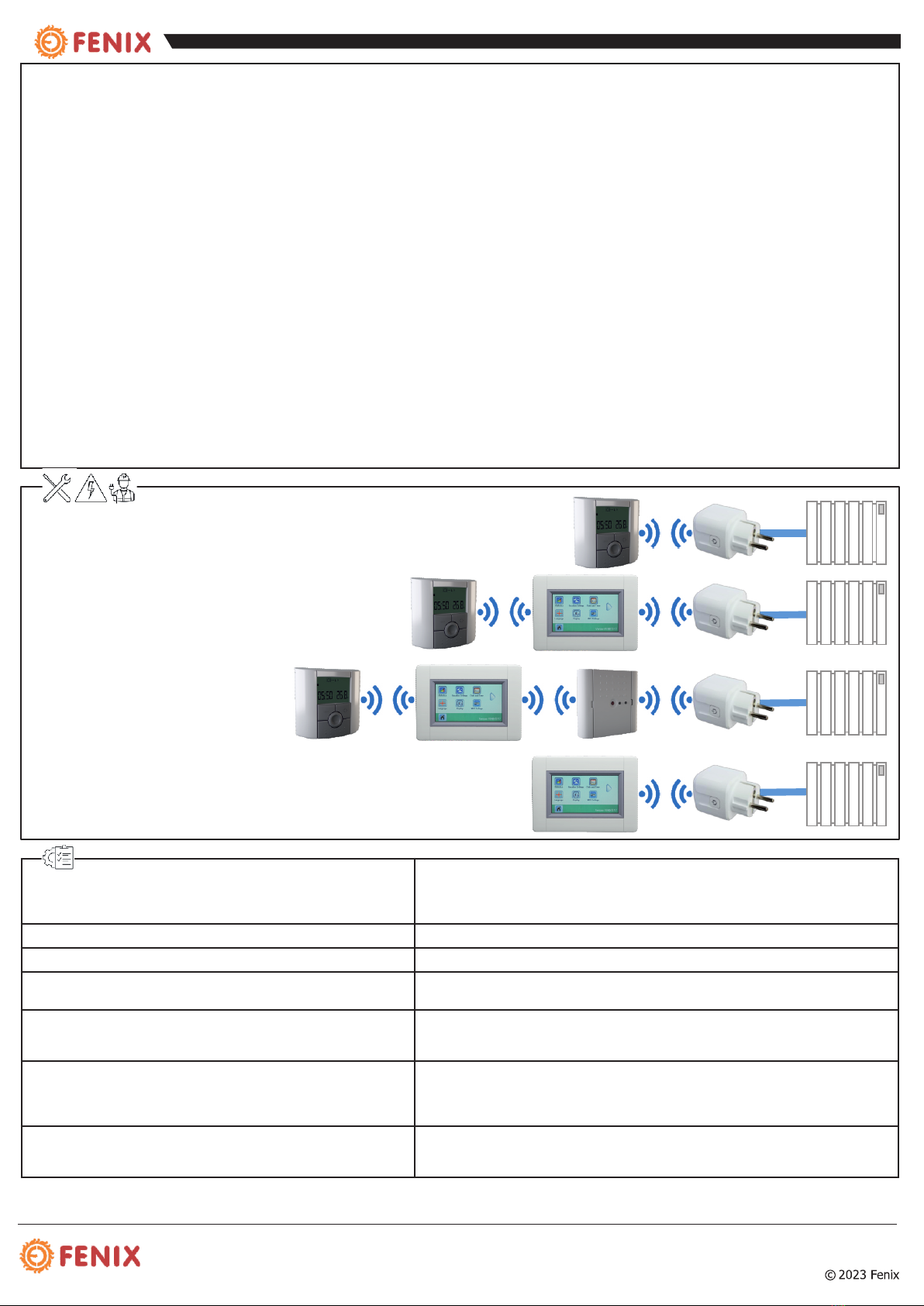
- The V25 receiver is a plug mounting receiver, specially designed to control an
electrical radiator regulation in combination with a wireless thermostat V22 type.
- This couple (Thermostat - Receiver) can also be managed by a Central V24 to
have a full control of your heating installation from one point.
- The V25 receiver can be used as slave unit of a V23 receiver.
- There is a possibility to use the V25 receiver as On/Off Timer in combination with a
V24 Central unit.
Make sure that all components of the wireless regulation system are marked with
the Fenix logo (description).
A combination with wireless products from different suppliers isn´t possible!
Box content
Install and plug the receiver into the following guidelines to guarantee an optimal reception:
- The receiver must be put at a minimum distance of 50cm of all others electrical or wireless materials like GSM, Wi-Fi router.
- Before wiring work related to the receiver must be carried out only when de-energized
- Connect your receiver to the power supply.
In order to maintain the correct installation of RF initialisation you need to follow next steps.
Installation 1: Receiver + RF thermostat
1. The receiver V25 must be put in OFF by pressing on the ON/OFF button
2. The receiver must be put in RF init mode by 2-10sec pressing on the ON/OFF Button.
3. Then the RF LED should flashes Red/Green indicating that the Receiver is now in radio configuration mode waiting for a thermostat configuration address.
4. Please refer to the thermostat leaflet to enter the thermostat in “RF Init” mode.
5. The receiver RF LED must become to be solid green, then change to off position or heating position, it depends on thermostat set temperature. Thermostat
should exit the RF init mode to indicate correct paring between both elements.
Installation 2: Receiver + RF Thermostat + RF Central
1.Make the “Installation 1” rules for pairing with the thermostat.
2. The receiver must be put one time more in RF init mode by 2-10 sec pressing on the On/Off Button.
3. Then the RF LED button should flashes Green and Red indicating that the Receiver is now in radio configuration mode waiting for a thermostat or V24
configuration address.
4. Please refer to the Central unit leaflet for more explanation about the pairing mode “RF Init”.
5. The receiver RF LED must become to be solid green, then change to off position or heating position, it depends on thermostat set temperature. The Central unit
will show a message to indicate correct paring between both elements.
TECHNOLOGY CHARACTERISTICS
N898_R00 (13.03.2023)
•
•
•
•
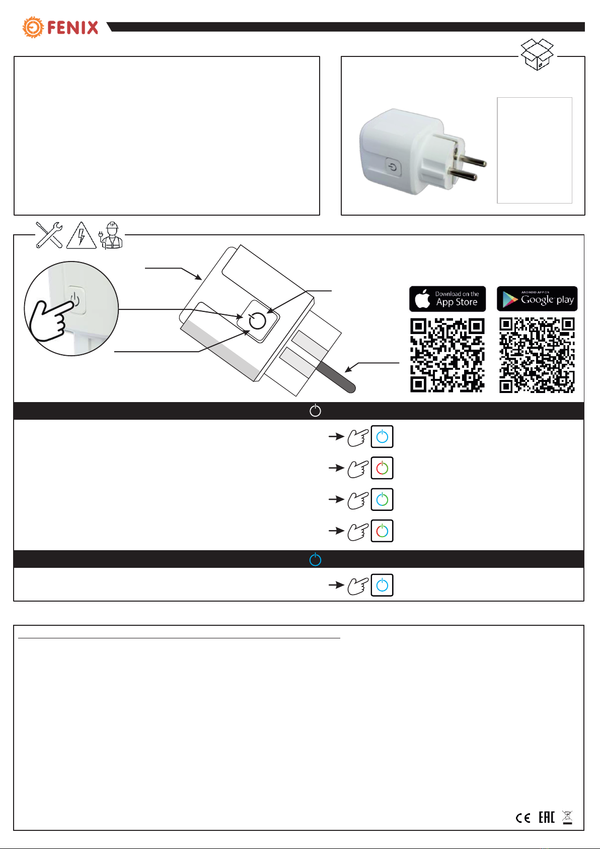
Switch the outlet ON/OFF
Pairing a socket with a Thermostat V22 and a Central unit V24 WIFI
Pairing a socket with a receiver (V23 - V26 master)
Reset the socket to a factory settings
1 sec
2-10 sec
2-10 sec
10+ sec
The LED will turn BLUE
LED flashes RED and GREEN
LED flashes BLUE and GREEN
The LED flashes GREEN and then
CONTROL FUNCTIONS FROM OUTLET - OFF POSITION
flashes 1x RED, GREEN, BLUE
Switching between pairing the outlet with the thermostat and the receiver is done by pressing the flashing
control button on the socket.
Switching between pairing the outlet with the thermostat and the receiver is done by pressing the flashing
control button on the socket.
•2-10 sec LED flashes BLUE
CONTROL FUNCTIONS FROM THE SOCKET - ON POSITION
Booster - Timer (default value 2h)
INLET
OUTLET
LED
POWER BUTTON
Smart wireless socket receiver
You will need the central Unit V24 and the Fenix
V24 WIFI Mobile app to control this socket
remotely. Only the Fenix V24 modular system is
compatible with this connection.

www.fenixgroup.cz
Fenix Trading s.r.o., Slezská 2790 01 Jeseník, Czech republic
+420 584 495 111
Installation 3: Receiver + RF Thermostat + RF Central + Slave receiver(s)
1. Make the “Installation 2” rules for pairing with the thermostat and the Central.
2. The Master receiver (receiver paired with the thermostat & Central) must be put in Receiver RF init mode by 10sec pressing on the RF Button (V24/V26 master).
3. Then the RF LED should be Green/Red fixed indicating that the Receiver is now in radio configuration mode waiting for a thermostat configuration address.
4. Put now the Slave receiver in RF init mode by 2-10sec pressing on the ON/OFF button, then touch the button again to switch the socket to the slave mode
(flashing BLUE/GREEN).
5. The Master and Slave receiver RF LED must be switched OFF to indicate correct paring between both elements.
6. You can link up to 3 Slave receivers on a Master receiver, to do this please repeat the steps 2 to 5 for each slave.
Note:
- The V25 slave receiver will follow the Master receiver.
- Only V25 receiver can be linked as a slave unit (Max 3 slaves).
Installation 4: Receiver + Central unit V24WIFI
1. The receiver must be put in RF init mode by 2-10sec pressing on the ON/OFF Button.
2. Then the RF LED button should flashes Green and Red indicating that the Receiver is now in radio configuration mode waiting for a V24 WIFI configuration
address.
3. Please refer to the Central unit V24 WIFI manual for installation procedure and adding ON/OFF zone.
4. The receiver RF LED must be switched OFF and the Central unit V24 WIFI will show a message to indicate correct pairing between both elements.
Note 1:
- In this way the V25 Receiver will work in a Timer mode, you will have the possibility to create a weekly program for ON/OFF period.
- You can also add 3 slaves V25 receiver units in this configuration.
Note 2:
In case of installation with V22 thermostat and loss of RF communication (RF Alarm), the receiver V25 will after 2 Hours cut off the power supply
and start flashing in Green to indicate a signal was lost.
INSTALLATION 1 :
INSTALLATION 2 :
INSTALLATION 3 :
INSTALLATION 4 :
Operating temperature
Shipping and storage
Thermal safety temperature
0°C 40°C
-10°C až +50°C
When > 85°C (back to the standard mode when 65°C)
Power supply 90- 230VAC 50Hz (with European plug socket)
Electrical protection Class II - IP20
Output
Maximum Resistive Load Relay
Relay 10Amps
250VAC 50Hz
Radio Frequency & RF
Receiving distance
868MHz < 10mW (Bidirectional communication)
100m in open space
30m in residential environment
Directive 2001/95/EC on General Products Safety Low voltage directive
2006/95/EEC Radio Equipment Directive 1995/5/EC-2014/53/EU ROHS
Directive 2011/65/EC The full text of the EU declaration of conformity is available
on wattswater.eu
Product confirmed on
Class
Contribution
UE 811/2013 and 2010/30/UE
IV
2%
Standards and approvals:
Your thermostat has been designed accordingly
with the following standards and other normative documents
« The descriptions and photographs contained in this product specification sheet are supplied by way of information only and are not binding. Fenix Trading s.r.o.reserves the right to carry out
any technical and design improvements to its products without prior notice. Warranty: All sales and contracts for sale are expressly conditioned on the buyer’s assent to Fenix terms and
conditions found on its website at fenixgroup.cz - Fenix hereby objects to any term, different from or additional to Fenix terms.
MASTER SLAVE (max.3x)
Quick Installation Manual (ENG)
Table of contents
Languages: