Fenner QD:HVAC User manual

Installation and
Operating
Instructions
AC Variable Speed Drive
0.75kW - 160kW
200 - 480 Volt 1 & 3 Phase
ııııııııııııııııııııııııııııııııııııııııııııııııııııııııııııııııııııııııııııııııııııııııııııııııııııııııııııııııııııııııııııııııııııııııııııııııııııııııııııııııııııııııııııııııııııııııııııııııı
www.fptgroup.com
HVAC
Installation & Operating Instructions
Page 2
ııııııııııııııııııııııııııııııııııııııııııııııııııııııııııııııııııııııııııııııııııııııııııııııııııııııııııııııııııııııııııııııııııııııııııııııııııııııııııııııııııııııııııııııııııııııııııııııııı
Page 2 www.fptgroup.com
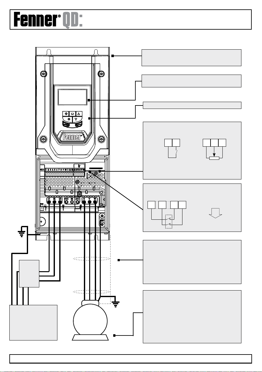
Mechanical Mounting
Information can be found on page 12
HVAC Display
(Status, diagnostics and programming)
1 2 5 6 7
SafeTorque Off (STO)
Link the terminals as shown, through the emergency
stop circuit contacts
Run - Stop 10K Pot
Motor Cable
For correct cable size, see technical data on page 66
Observe the maximum permissible motor cable length
For motor cable lengths > 50 metres, an output filter
is recommended
Use a screened (shielded cable). The shield should be
bonded to earth at both ends.
Motor Connection
Check for Star or Delta Connection
Enter the Motor Nameplate data into the drive param-
eters as follows:
lMotor Rated Voltage : P1-07
lMotor Rated Current : P1-08
lMotor Rated Frequency : P1-09
lMotor Rated Speed (Optional) : P1-10
Keypad Operation can be found on page 21
Close the switch to run (enable),
Open to stop
M
AC Supply Connections
200-240 Volts +/- -10%
380-480 Volts +/- -10%
Check drive rating info on page 63
PE L1 L2 L3
Fuses or
MCB
Check
drive rating
information
on page 64
Easy Start Up Guide: QD:HVAC IP55
Control Terminals
Configuration based on factory settings.
1 9 12 13 Inhbit
stop

ııııııııııııııııııııııııııııııııııııııııııııııııııııııııııııııııııııııııııııııııııııııııııııııııııııııııııııııııııııııııııııııııııııııııııııııııııııııııııııııııııııııııııııııııııııııııııııııııı
www.fptgroup.com
HVAC
Installation & Operating Instructions
Page 3
ııııııııııııııııııııııııııııııııııııııııııııııııııııııııııııııııııııııııııııııııııııııııııııııııııııııııııııııııııııııııııııııııııııııııııııııııııııııııııııııııııııııııııııııııııııııııııııııııı
Page 3
www.fptgroup.com
HVAC Display
Status, Diagnostics and
Programming
Control terminals
Based on factory settings
1 2 5 6 7
1 9 12 13
SafeTorque Off (STO)
Link the terminals as shown,
through the emergency stop
circuit contacts
10K Speed
Pot
Run - Stop
M
Motor Cable
Check the rating information on
page 64
Motor Connection
Check for Star or Delta Connection
according to the motor voltage
rating - see page 17
Enter the Motor Nameplate data
into the drive parameters as
follows:
lMotor Rated Voltage : P1-07
lMotor Rated Current : P1-08
lMotor Rated Frequency : P1-09
lMotor Rated Speed (Optional) : P1-10
AC Supply Connection
200 - 240 Volts +/- 10%
380 - 480 Volts +/- 10%
Check the drive rating
information on page 63
L3L1 L2
Mechanical Mounting
Information can be found on
page 9
Keypad Operation can be
found on page 21
Close the switch to run (enable),
Open the switch to stop
PE
Fuses or
MCB
Check the
drive rating
information
on page 65
Applies to switched
version only in-built
isolator:
Mains power On/Off
Easy Start Up Guide: QD:HVAC IP66
ııııııııııııııııııııııııııııııııııııııııııııııııııııııııııııııııııııııııııııııııııııııııııııııııııııııııııııııııııııııııııııııııııııııııııııııııııııııııııııııııııııııııııııııııııııııııııııııııı
www.fptgroup.com
HVAC
Installation & Operating Instructions
Page 4
Declaration of Conformity
ERIKS Industrial Services Ltd hereby states that the
Fenner QD product range conforms to the relevant
safety provisions of the Low Voltage Directive
2006/95/EC and the EMC Directive 2004/108/EC and
has been designed and manufactured in accordance
with the following harmonised European standards:
EN 61800-5-1: 2003 Adjustable speed electrical
power drive systems. Safety
requirements. Electrical,
thermal and energy.
EN 61800-3 2nd Ed: 2004 Adjustable speed electrical
power drive systems. EMC
requirements and specific test
methods.
EN 55011:2007 Limits and Methods of
measurement of radio
disturbance characteristics
of industrial, scientific and
medical (ISM) radio-frequency
equipment (EMC).
EN60529:1992 Specifications for degrees
of protection provided by
enclosures.
Electromagnetic Compatibility
All Fenner drives are designed with high standards of
EMC in mind. All versions suitable for operation on
Single Phase 230 volt and Three Phase 400 volt
supplies and intended for use within the European
Union are fitted with an internal EMC filter. This EMC
filter is designed to reduce the conducted emissions
back into the supply via the power cables for
compliance with harmonised European standards.
It is the responsibility of the installer to ensure that the
equipment or system into which the product is
incorporated complies with the EMC legislation of the
country of use. Within the European Union, equipment
into which this product is incorporated must comply
with the EMC Directive 2004/108/EC. When using an
Fenner drive with an internal or optional external filter,
compliance with the following EMC Categories, as
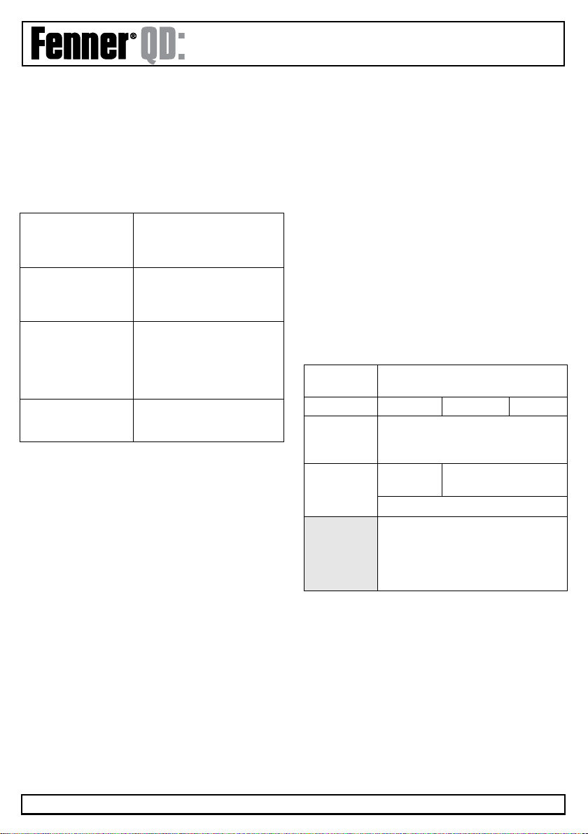
defined by EN61800-3:2004 can be achieved:
Drive Type /
Rating
EMC Category
Cat C1 Cat C2 Cat C3
1 Phase,
230 Volt
Input
No additional filtering required.
Use shielded motor cable.
3 Phase,
400 Volt
Input
Use external
filter
No additional filtering
required
Use shielded motor cable
Note
For motor cable lengths greater than
100m, an output dv / dt filter must be
used. For further information contact
your Fenner distributor.
All rights reserved. No part of this User Guide may be
reproduced or transmitted in any form or by any means,
electrical or mechanical including photocopying, recording or
by any information storage or retrieval system without
permission in writing from the publisher.
Copyright ERIKS Industrial Services Ltd © 2012
ERIKS Industrial Services Ltd, Amber Way, Halesowen,
West Midlands, B62 8WG
The manufacturer accepts no liability for any consequences
resulting from inappropriate, negligent or incorrect
installation, or adjustment of the optional operating
parameters of the drive or from mismatching of the drive to
the motor.
The contents of this User Guide are believed to be correct
at the time of printing. In the interest of a commitment to a
policy of continuous improvement, the manufacturer
reserves the right to change the specification of the product
or its performance or the contents of the User Guide
without notice.
All Fenner QD Series products carry a 2-year warranty, valid
from the date of manufacture. This date is clearly visible on
the product rating label.

ııııııııııııııııııııııııııııııııııııııııııııııııııııııııııııııııııııııııııııııııııııııııııııııııııııııııııııııııııııııııııııııııııııııııııııııııııııııııııııııııııııııııııııııııııııııııııııııııı
www.fptgroup.com
HVAC
Installation & Operating Instructions
Page 5
1. IntroductIon
1.1 Important Safety Information 4
2. General InformatIon and ratInGs 7
3. mechanIcal InstallatIon 9
3.1 General 9
3.2 Before Installation 9
3.3 UL Compliant Installation 9
3.4 Mechanical dimensons and mounting IP66 9
3.5 Mechnical dimensions and mounting IP55 10
3.6 Guidelines for enclosure moutning IP55 & 66 11
3.7 Removing the Terminal Cover 11
3.8 Lock off 14
4. electrIcal InstallatIon 15
4.1 Grounding the Drive 15
4.2 Wiring Precautions 16
4.3 Incoming Power Connection 16
4.4 Drive and motor connection 16
4.5 Motor Terminal Box Connections 17
4.6 Motor Thermistor Connection 17
4.7 Control Terminal Wiring 17
4.8 Control Terminals Connection Diagram 18
4.9 Control Terminal Connections 18
5. manaGInG the Keypad 19
5.1 Keypad Layout and Function 19
5.2 Changing Parameters 19
5.3 Accessing and changing parameter values 20
5.4 Keypad Layout and Function OLED 21
5.5 Drive Operating Display OLED 21
5.6 Accessing and Changing Parameter Values OLED 21
5.7 Resetting Parameters to Factory Default OLED 22
5.8 Resetting Parameter to Use Default Settings 22
5.9 Changing the Language on OLED Display 23
5.10 Selecting between Hand and Auto Control OLED 23
6. commIssIonInG 24
7. hVac specIfIc feature setup 25
7.1 Pump Staging DOL Cascade 25
7.2 Pump Staging Multiple Drive Cascade 27
7.3 Maintenance Internal Set-up & Reset 28
7.4 Load Profile Monitoring Function 30
7.5 Pump Clean Function 31
7.6 Pump Stir Function 33
7.7 Bypass Control Fuction 33
7.8 Fire Mode Function 35
7.9 Motor Pre-heat Function & DC Injection 37
8 pId control applIcatIons 39
8.1 Overview 39
8.2 PID Function Set-Up 39
8.3 Application Example 43
9. parameters 44
10.dIGItal Input functIons 46
10.1 Digital Input Configuration Parameter P1-13 46
11. extened parameters 47
11.1 Parameter Group 2 - Extended 47
11.2 Parameter Group 3 - PID Control 52
11.3 Parameter Group 4 - Motor Control 53
11.4 Parameter Group 5 - Communication 53
11.5 Parameter Group 6 - Advanced Features 54
11.6 Parameter Group 8 - HVAC Functions 55
11.7 Parameter Group 9 - Advanced Control Logic 57
11.8 Parameter Group 0 - Monitoring 57
12. serIal communIcatIons 61
12.1 RS-485 Communications 61
12.2 Modbus RTU Communications 61
13.technIcal data 63
13.1 Environmental 63
13.2 Input Voltage Ranges 63
13.3 Maximum Supply Ratings for UL Compliance 63
13.4 Output Power & Current Ratings 64
13.5 Additional Information for UL Approved 65
14.parameter chanGe tables 66
15.troubleshootInG 67
ııııııııııııııııııııııııııııııııııııııııııııııııııııııııııııııııııııııııııııııııııııııııııııııııııııııııııııııııııııııııııııııııııııııııııııııııııııııııııııııııııııııııııııııııııııııııııııııııı
www.fptgroup.com
HVAC
Installation & Operating Instructions
Page 6
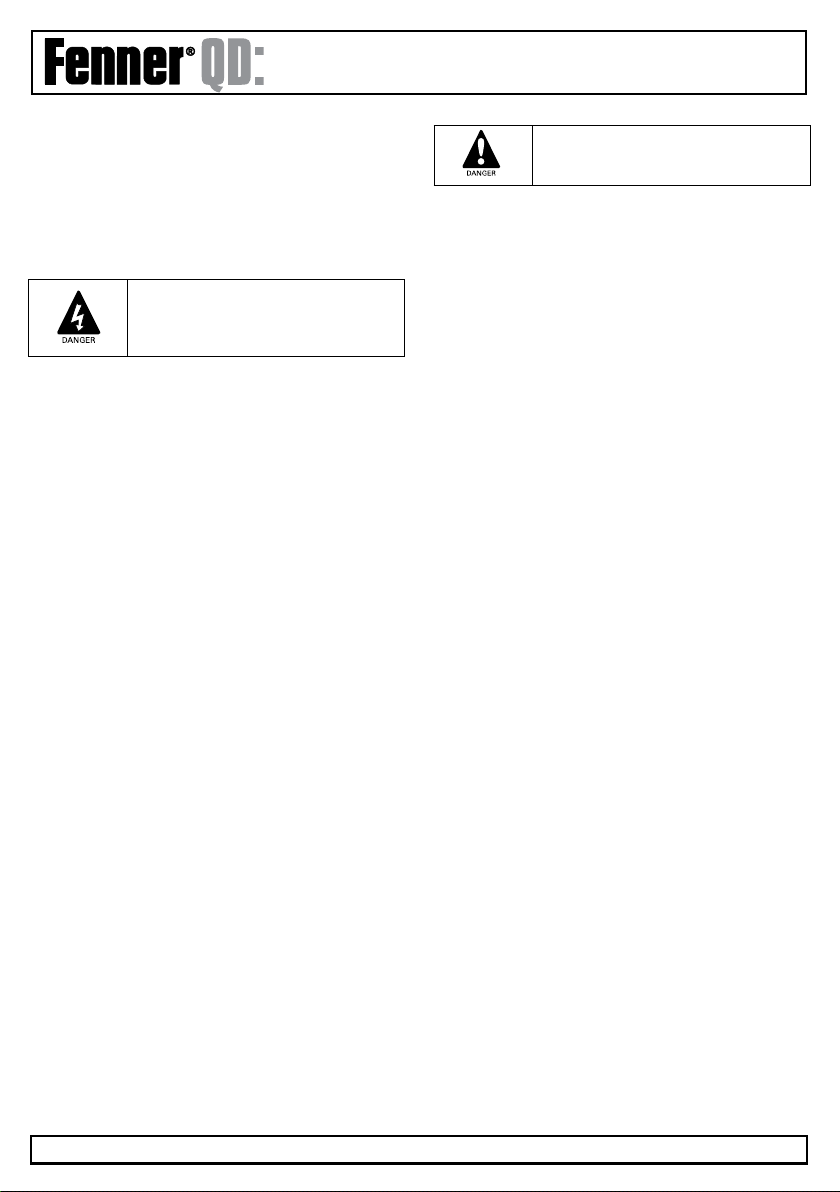
Danger: Indicates a potentially hazardous
situation other than electrical, which if not
avoided, could result in damage to property.
Within the European Union, all machinery in which this product
is used must comply with Directive 98/37/EC, Safety of Machin-
ery. In particular, the machine manufacturer is responsible for
providing a main switch and ensuring the electrical equipment
complies with EN60204-1.
The level of integrity offered by the Fenner QD:HVAC control input
functions (excluding the ‘Safe Torque Free Input’) – for example
stop/start, forward/reverse and maximum speed, is not sufficient
for use in safety-critical applications without independent channels
of protection. All applications where malfunction could cause injury
or loss of life must be subject to a risk assessment and further
protection provided where needed.
The driven motor can start at power up if the enable input
signal is present.
The STOP function does not remove potentially lethal high
voltages. ISOLATE the drive and wait 10 minutes before starting
any work on it. Never carry out any work on the Drive, Motor or
Motor cable whilst the input power is still applied.
The drive can be programmed to operate the driven motor at
speeds above or below the speed achieved when connecting
the motor directly to the mains supply. Obtain confirmation
from the manufacturers of the motor and the driven machine
about suitability for operation over the intended speed range
prior to machine start up.
Do not activate the automatic fault reset function on any systems
whereby this may cause a potentially dangerous situation.
The Fenner QD:HVAC has an Ingress Protection rating of IP20
or IP55 depending on the model. IP20 units must be installed
in a suitable enclosure.
Fenner QD: HVAC drives are intended for indoor use only.
When mounting the drive, ensure that sufficient cooling is
provided. Do not carry out drilling operations with the drive in
place, dust and swarf from drilling may lead to damage.
The entry of conductive or flammable foreign bodies should be
prevented. Flammable material should not be placed close to
the drive
Relative humidity must be less than 95% (non-condensing).
Ensure that the supply voltage, frequency and no. of phases (1
or 3 phase) correspond to the rating of the drive as delivered.
Never connect the mains power supply to the Output
terminals U, V, W.
Do not install any type of automatic switchgear between the
drive and the motor
Wherever control cabling is close to power cabling, maintain a
minimum separation of 100 mm and arrange crossings at 90
degrees
Ensure that all terminals are tightened to the appropriate
torque setting
Do not attempt to carry out any repair of the Fenner QD:HVAC
In the case of suspected fault or malfunction, contact your
local Fenner distributor.
1. Introduction
1.1 Important Safety Information
Please read the important safety information
below, and all Warning and Caution Information
elsewhere in this manual.
Danger: Indicates a risk of electric shock,
which, if not avoided, could result in
damage to the equipment and possible
injury or death.
This variable speed drive product (Fenner QD:HVAC) is
intended for professional incorporation into complete
equipment or systems as part of a fixed installation. If installed
incorrectly it may present a safety hazard. The Fenner
QD:HVAC uses high voltages and currents, carries a high level
of stored electrical energy, and is used to control mechanical
plant that may cause injury. Close attention is required to
system design and electrical installation to avoid hazards in
either normal operation or in the event of equipment
malfunction. Only qualified electricians are allowed to install
and maintain this product.
System design, installation, commissioning and maintenance
must be carried out only by personnel who have the necessary
training and experience. They must carefully read this safety
information and the instructions in this Guide and follow all
information regarding transport, storage, installation and use of
the drive, including the specified environmental limitations.
Do not perform any flash test or voltage withstand test on the
drive. Any electrical measurements required should be carried
out with the drive disconnected.
Electric shock hazard! Disconnect and ISOLATE the Fenner
QD:HVAC before attempting any work on it. High voltages are
present at the terminals and within the drive for up to 10
minutes after disconnection of the electrical supply. Always
ensure by using a suitable multimeter that no voltage is present
on any drive power terminals prior to commencing any work.
Where supply to the drive is through a plug and socket
connector, do not disconnect until 10 minutes have elapsed
after turning off the supply.
Ensure correct earthing connections. The earth cable must
be sufficient to carry the maximum supply fault current which
normally will be limited by the fuses or MCB. Suitably rated
fuses or MCB should be fitted in the mains supply to the
drive, according to any local legislation or codes.
Do not carry out any work on the drive control cables whilst
power is applied to the drive or to the external control circuits.

ııııııııııııııııııııııııııııııııııııııııııııııııııııııııııııııııııııııııııııııııııııııııııııııııııııııııııııııııııııııııııııııııııııııııııııııııııııııııııııııııııııııııııııııııııııııııııııııııı
www.fptgroup.com
HVAC
Installation & Operating Instructions
Page 7
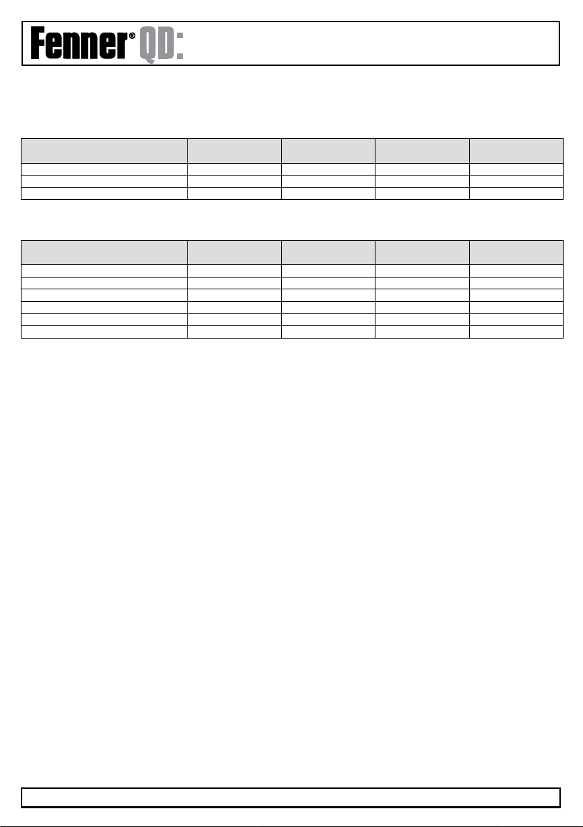
2. General Information and Ratings
2.1 Drive Model Numbers IP55
kW Model with Filter kW HP Output
Current (A)
Frame Size
575F20P7 0.75 1 4.3 2
575F21P5 1. 5 272
575F22P2 2.2 3 10.5 2
kW Model with Filter kW HP Output
Current (A)
Frame Size
575F30P7 0.75 1 4.3 2
575F31P5 1. 5 272
575F32P2 2.2 3 10.5 2
575F34P0 4 5 18 3
575F35P5 5.5 7. 5 25 3
575F37P5 7. 5 10 39 4
575F3011 11 15 46 4
575F3015 15 20 61 5
575F3018 18.5 25 72 5
575F3022 22 30 90 5
575F3030 30 40 110 6
575F3037 37 50 150 6
575F3045 45 60 180 6
575F3055 55 75 202 6
575F3075 75 100 240 7
575F3090 90 120 300 7
kW Model with Filter 22kW HP Output
Current (A)
Frame Size
575F40P7 0.75 1 2.2 2
575F41P5 1. 5 2 4.1 2
575F42P2 2.2 3 5.8 2
575F44P0 4 5 9.5 2
575F45P5 5.5 7. 5 14 3
575F47P5 7. 5 10 18 3
575F4011 11 15 25 4
575F4015 15 20 30 4
575F4018 18.5 25 39 4
575F4022 22 30 46 4
575F4030 30 40 61 5
575F4037 37 50 72 5
575F4045 45 60 90 5
575F4055 55 75 110 6
575F4075 75 120 150 6
575F4090 90 150 180 6
575F4110 110 175 202 6
575F4132 132 200 240 7
575F4160 160 250 300 7
200-240V 10% - 1 Phase Input
200-240V 10% - 3 Phase Input
380-400V 10% - 3 Phase Input
575F20P7
Series &
Enclosure
Inverter
Type
Supply
Voltage
Rated
Power
ııııııııııııııııııııııııııııııııııııııııııııııııııııııııııııııııııııııııııııııııııııııııııııııııııııııııııııııııııııııııııııııııııııııııııııııııııııııııııııııııııııııııııııııııııııııııııııııııı
www.fptgroup.com
HVAC
Installation & Operating Instructions
Page 8
2.2 Drive Model Numbers IP66
kW Model with Filter kW HP Output
Current (A)
Frame Size
576F20P7 0.75 1 4.3 2
576F21P5 1. 5 272
576F22P2 2.2 3 10.5 2
kW Model with Filter kW HP Output
Current (A)
Frame Size
576F40P7 0.75 1 2.2 2
576F41P5 1. 5 2 4.1 2
576F42P2 2.2 3 5.8 2
576F44P0 4 5 9.5 2
576F45P5 5.5 7. 5 14 3
576F47P5 7. 5 10 18 3
200-240V 10% - 1 Phase Input
380-480VV 10% - 3 Phase Input
ııııııııııııııııııııııııııııııııııııııııııııııııııııııııııııııııııııııııııııııııııııııııııııııııııııııııııııııııııııııııııııııııııııııııııııııııııııııııııııııııııııııııııııııııııııııııııııııııı
www.fptgroup.com
HVAC
Installation & Operating Instructions
Page 9
3. Mechanical Installation
3.1. General
• The Fenner QD:HVAC should be mounted in a vertical position only on a flat, flame resistant vibration free mounting using
the integral holes.
• The Fenner QD:HVAC must be installed in a pollution degree 1 or 2 environment only.
• Do not mount flammable material close to the drive
• Ensure that the minimum cooling air gaps, as detailed in section 3.7 are left clear
• Ensure that the ambient temperature range does not exceed the permissible limits for the Fenner QD:HVAC given in
section 13.1
• Provide suitable clean, moisture and contaminant free cooling air sufficient to fulfil the cooling requirements of the Fenner
QD:HVAC according to section 13.1
3.2. Before Installation
• Carefully unpack the QD:HVAC and check for any signs of damage. Notify the shipper immediately if any exist.
• Check the drive rating label to ensure it is of the correct type and power requirements for the application.
• Store the QD:HVAC in its box until required. Storage should be clean and dry and within the temperature range –40°C to +60°C
3.3. UL Compliant Installation
Note the following for UL compliant installation:
• For an up to date list of UL compliant products, please refer to UL listing NMMS.E226333
• The drive can be operated within an ambient temperature range as stated in section 13.1
• For IP20 units, installation is required in a pollution degree 1 environment
• For IP55 & IP66 units, installation in a pollution degree 2 environment is permissible
• UL Listed ring terminals / lugs must be used for all bus bar and grounding connections
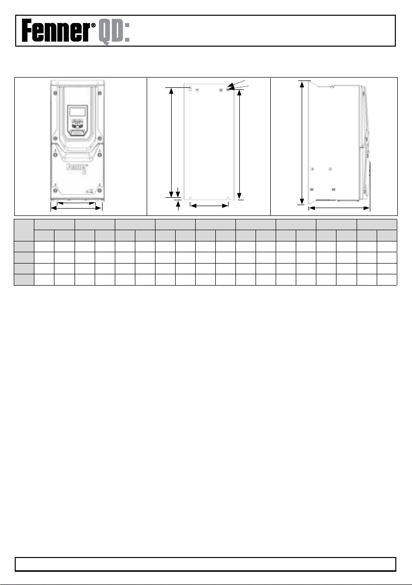
3.4 Mechanical Dimensions and Mounting - IP66 Units
Drive
Size
A B D E F G H I J
mm in mm in mm in mm in mm in mm in mm in mm in mm in
2257.0 10.12 220.0 8.67 28.5 1. 12 28.5 1. 12 238 9.37 188.0 7. 4 176.0 6.93 4.2 0.17 8.5 0.33
3310.0 12.20 276.5 10.89 251.5 9.90 33.4 1.31 256 10.08 210.5 8.29 197.5 7.78 4.2 0.17 8.5 0.33
Control terminal torque settings: All Sizes: 0.8Nm
Power terminal torque settings: All Sizes: 1Nm
I
J
D
B
E
H
G
A
F
ııııııııııııııııııııııııııııııııııııııııııııııııııııııııııııııııııııııııııııııııııııııııııııııııııııııııııııııııııııııııııııııııııııııııııııııııııııııııııııııııııııııııııııııııııııııııııııııııı
www.fptgroup.com
HVAC
Installation & Operating Instructions
Page 10
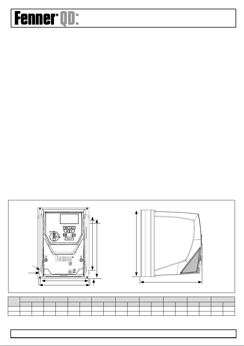
3.5 Mechanical Dimensions and Mounting - IP55
Drive
Size
A B C D E F G H I
mm in mm in mm in mm in mm in mm in mm in mm in mm in
4440 17.32 418 16.46 423 16.65 8 0.315 230 9.06 173 6.81 110 4.33 4.25 0.167 7. 5 0.295
5540 21.26 515 20.28 520 20.47 8 0.315 270 10.63 235 9.25 175 6.89 4.25 0.167 7. 5 0.295
6865 34.06 830 32.68 840 33.07 10 0.394 340 13.39 290 11.42 200 7.87 5.5 0.217 11 0.433
71280 50.39 1245 49.02 1255 49.41 10 0.394 370 14.57 330 12.99 200 7.87 5.5 0.217 11 0.433
Control terminal torque settings: All sizes: 0.8Nm
Power terminal torque settings: Frame size 4: 1.2-1.5Nm
Frame size 5: 2.5 - 4.5Nm
Frame size 6 & 7: 8Nm
G
F
CA
E
H
G
D
B
I

ııııııııııııııııııııııııııııııııııııııııııııııııııııııııııııııııııııııııııııııııııııııııııııııııııııııııııııııııııııııııııııııııııııııııııııııııııııııııııııııııııııııııııııııııııııııııııııııııı
www.fptgroup.com
HVAC
Installation & Operating Instructions
Page 11
3.6 Guidelines for enclosure mounting IP55 and IP66 units
• Before mounting the drive, ensure that the chosen location meets the environmental condition requirements for the drive
shown in section 13.1
• The drive must be mounted vertically, on a suitable at surface
• The minimum mounting clearances as shown in the table below must be observed
• The mounting site and chosen mountings should be sufcient to support the weight of the drives
Drive Size X Above & Below Y Either Side
mm in mm in
2 (IP66) 150 5.9 10 0.394
3 (IP66) 150 5.9 10 0.394
4 (IP55) 200 7. 9 10 0.394
5 (IP55) 200 7. 9 10 0.394
6 (IP55) 200 7. 9 10 0.394
7 (IP55) 200 7. 9 10 0.394
Note:
Typical drive heat losses are 3% of operating load conditions
Above are guidelines only and the operating ambient temperature
of the drive MUST be maintained at all times.
3.7 Removing the Terminal Cover
3.7.1 Frame Size 2
Terminal Cover Release Screws
3.7.2 Frame Size 3
Using a suitable
flat blade
screwdriver,
rotate the four
retaining screws
indicated until the
screw slot is
vertical
Using a suitable
flat blade
screwdriver,
rotate the four
retaining screws
indicated until the
screw slot is
vertical
X
X
YY

ııııııııııııııııııııııııııııııııııııııııııııııııııııııııııııııııııııııııııııııııııııııııııııııııııııııııııııııııııııııııııııııııııııııııııııııııııııııııııııııııııııııııııııııııııııııııııııııııı
www.fptgroup.com
HVAC
Installation & Operating Instructions
Page 12
3.7.3 Frame Size 6
Remove the two screws
indicated, lift the cover
forwards and off. To refit
the cover, slide the top
locating lugs upwards
under the top cover, then
re-fasten the lower cover
screws.
3.7.3 Frame Size 4 3.7.2 Frame Size 5
Using a suitable
flat blade
screwdriver,
rotate the four
retaining screws
indicated until the
screw slot is
vertical.
Using a suitable
flat blade
screwdriver,
rotate the four
retaining screws
indicated until the
screw slot is
vertical

ııııııııııııııııııııııııııııııııııııııııııııııııııııııııııııııııııııııııııııııııııııııııııııııııııııııııııııııııııııııııııııııııııııııııııııııııııııııııııııııııııııııııııııııııııııııııııııııııı
www.fptgroup.com
HVAC
Installation & Operating Instructions
Page 13
3.7.4 Frame Size 7
Using a suitable flat blade
screwdriver, rotate the four
retaining screws indicated
until the screw slot is vertical.

ııııııııııııııııııııııııııııııııııııııııııııııııııııııııııııııııııııııııııııııııııııııııııııııııııııııııııııııııııııııııııııııııııııııııııııııııııııııııııııııııııııııııııııııııııııııııııııııııı
www.fptgroup.com
HVAC
Installation & Operating Instructions
Page 14
3.8 Lock Off
Power Isolator Lock Off - IP66 with Built in Isolater Option
On the switched models the main power islator switch can be locked in the ‘off’ position using a 20mm standrad shackle
padlock (not supplied)
ııııııııııııııııııııııııııııııııııııııııııııııııııııııııııııııııııııııııııııııııııııııııııııııııııııııııııııııııııııııııııııııııııııııııııııııııııııııııııııııııııııııııııııııııııııııııııııııııı
www.fptgroup.com
HVAC
Installation & Operating Instructions
Page 15
4. Electrical Installation
4.1 Grounding the Drive
This manual is intended as a guide for proper
installation. ERIKS Industrial Services cannot
assume responsibility for the compliance or the
non-compliance to any code, national, local or
otherwise, for the proper installation of this drive or
associated equipment. A hazard of personal injury and/or
equipment damage exists if codes are ignored during
installation.
This Fenner QD drive contains high voltage
capacitors that take time to discharge after
removal of the main supply. Before working on the
drive, ensure isolation of the main supply from line
inputs. Wait ten (10) minutes for the capacitors to discharge
to safe voltage levels. Failure to observe this precaution
could result in severe bodily injury or loss of life.
Only qualified electrical personnel familiar with the
construction and operation of this equipment and
the hazards involved should install, adjust, operate,
or service this equipment. Read and understand
this manual and other applicable manuals in their entirety
before proceeding. Failure to observe this precaution could
result in severe bodily injury or loss of life.
4.1.1 Grounding Guidelines
The ground terminal of each Fenner QD:HVAC should be
individually connected DIRECTLY to the site ground bus bar
(through the filter if installed). Fenner QD ground
connections should not loop from one drive to another, or
to, or from any other equipment. Ground loop impedance
must confirm to local industrial safety regulations. To meet
UL regulations, UL approved ring crimp terminals should be
used for all ground wiring connections. The drive Safety
Ground must be connected to system ground. Ground
impedance must conform to the requirements of national
and local industrial safety regulations and/or electrical
codes. The integrity of all ground connections should be
checked periodically.
4.1.2. Protective Earth Connector
The cross sectional area of the PE Conductor must be at
least equal to that of the incoming supply conductor.
4.13 Safety Ground
This is the safety ground for the drive that is required by
code. One of these points must be connected to adjacent
building steel (girder, joist), a floor ground rod, or bus bar.
Grounding points must comply with national and local
industrial safety regulations and/or electrical codes.
4.1.4. Motor Ground
The motor ground must be connected to one of the ground
terminals on the drive.
4.1.5. Ground Fault Monitoring
As with all inverters, a leakage current to earth can exist.
The Fenner QD:HVAC is designed to produce the minimum
possible leakage current whilst complying with worldwide
standards. The level of current is affected by motor cable
length and type, the effective switching frequency, the earth
connections used and the type of RFI filter installed. If an
ELCB (Earth Leakage Circuit Breaker) is to be used, the
following conditions apply:
• A Type B Device must be used
• The device must be suitable for protecting equipment
with a DC component in the leakage current
• Individual ELCBs should be used for each Fenner drive
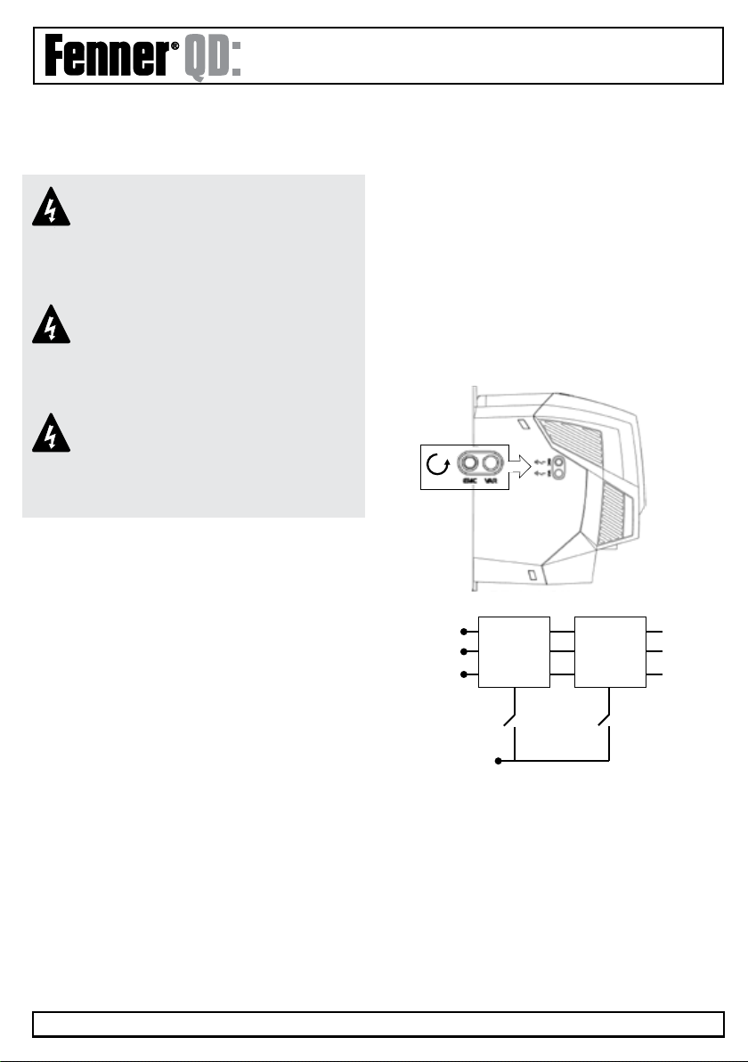
Drives with a EMC filter have an inherently higher leakage
current to ground (Earth). For applications where tripping
occurs the EMC filter can be disconnected (on IP20 units
only) by removing the EMC screws on the side of the
product.
The Fenner QD:HVAC range has input supply voltage surge
supression components fitted to protect the drive from
voltage transients, typically originating from lightening
strikes or switching of high power equipment on the same
supply.
4.1.6. Shield Termination (Cable Screen)
The safety ground terminal provides a grounding point for
the motor cable shield. The motor cable shield connected to
this terminal (drive end) should also be connected to the
motor frame (motor end). Use a shield terminating or EMI
clamp to connect the shield to the safety ground terminal.
Internal
EMC
Filter
Internal
Surge
Protection
EMC VAR
Earth
L/L1
N/L2
L3

ııııııııııııııııııııııııııııııııııııııııııııııııııııııııııııııııııııııııııııııııııııııııııııııııııııııııııııııııııııııııııııııııııııııııııııııııııııııııııııııııııııııııııııııııııııııııııııııııı
www.fptgroup.com
HVAC
Installation & Operating Instructions
Page 16
4.2. Wiring Precautions
Connect the Fenner QD:HVAC according to section 4.3 and
4.4, ensuring that motor terminal box connections are
correct. There are two connections in general: Star and
Delta. It is essential to ensure that the motor is connected
in accordance with the voltage at which it will be operated.
For more information, refer to section 4.5 Motor Terminal
Box Connections.
It is recommended that the power cabling should be 4-core
PVC-insulated screened cable, laid in accordance with local
industrial regulations and codes of practice.
4.3 Incoming Power Connection
• For a single phase supply, power should be connected to
L1/L, L2/N.
• For 3 phase supplies power should be connected to L1,
L2, and L3. Phase sequence is not important.
• For compliance with CE and C Tick EMC requirements, a
symmetrical shielded cable is recommended.
• A fixed installation is required according to IEC61800-5-1
with a suitable disconnecting device installed between
the Fenner drive and the AC Power Source. The
disconnecting device must conform to the local safety
code / regulations (e.g. within Europe, EN60204-1, Safety
of machinery).
• The cables should be dimensions according to any local
codes or regulations. Guideline dimensions are given in
section13.4.
• Suitable fuses to provide wiring protection of the input
power cable should be installed in the incoming supply
line, according to the data in section 13.4. The fuses must
comply with any local codes or regulations in place. In
general, type gG (IEC 60269) or UL type T fuses are
suitable; however in some cases type aR fuses may be
required. The operating time of the fuses must be below
0.5 seconds.
• Where allowed by local regulations, suitably dimensioned
type B MCB circuit breakers of equivalent rating may be
utilised in place of fuses, providing that the clearing
capacity is sufficient for the installation.
• When the power supply is removed from the drive, a
minimum of 30 seconds should be allowed before
re-applying the power. A minimum of 10 minutes should
be allowed before removing the terminal covers or
connection.
• The maximum permissible short circuit current at the Fenner
drive Power terminals as defined in IEC60439-1 is 100kA.
• An optional Input Choke is recommended to be installed
in the supply line for drives where any of the following
conditions occur:-
• The incoming supply impedance is low or the fault
level / short circuit current is high
• The supply is prone to dips or brown outs
• An imbalance exists on the supply (3 phase drives)
• The power supply to the drive is via a bus-bar and
brush gear system (typically overhead Cranes).
• In all other installations, an input choke is recommended
to ensure protection of the drive against power supply
faults. Refer to your local Fenner Authorised Distributor
for available options
• Fenner QD:HVAC models in frame sizes 4 to 8 are factory
fitted with an Input choke as standard.
4.4 Drive and Motor Connection
• The motor should be connected to the Fenner drive U, V,
and W terminals using a suitable 3 or 4 core cable. Where
a 3 core cable is utilised, with the shield operating as an
earth conductor, the shield must have a cross sectional
area at least equal to the phase conductors when they
are made from the same material. Where a 4 core cable
is utilised, the earth conductor must be of at least equal
cross sectional area and manufactured from the same
material as the phase conductors.
• The motor earth must be connected to one of the drive
earth terminals.
• For compliance with the European EMC directive, a
suitable screened (shielded) cable should be used.
Braided or twisted type screened cable where the screen
covers at least 85% of the cable surface area, designed
with low impedance to HF signals are recommended as a
minimum. Installation within a suitable steel or copper
tube is generally also acceptable.
• The cable screen should be terminated at the motor end
using an EMC type gland allowing connection to the
motor body through the largest possible surface area
• Where drives are mounted in a steel control panel
enclosure, the cable screen may be terminated directly to
the control panel using a suitable EMC clamp or gland, as
close to the drive as possible.
• For IP55 drives, connect the motor cable screen to the
internal ground clamp

ııııııııııııııııııııııııııııııııııııııııııııııııııııııııııııııııııııııııııııııııııııııııııııııııııııııııııııııııııııııııııııııııııııııııııııııııııııııııııııııııııııııııııııııııııııııııııııııııı
www.fptgroup.com
HVAC
Installation & Operating Instructions
Page 17
4.5. Motor Terminal Box Connections
Most general purpose motors are wound for operation on dual voltage supplies. This is indicated on the nameplate of the motor.
This operational voltage is normally selected when installing the motor by selecting either STAR or DELTA connection. STAR
always gives the higher of the two voltage ratings.
Incoming Sup-
ply Voltage
Motor Nameplate
Voltages
Connection
230 230/400
Delta
400 400/690
400 230/400 Star
4.6. Motor Thermistor Connection
Where a motor thermistor is to be used, it should be connected as follows:
1 2 876543 109
Control Terminal Strip
Additional Information
Compatible Thermistor : PTC Type, 2.5kΩtrip level
Use a setting of P1-13 that have Input 5 function as External Trip, e.g. P1-13 = 6. Refer to section 7 for further details.
4.7 Control Terminal Wiring
• All analog signal cables should be suitably shielded. Twisted pair cables are recommended.
• Power and Control Signal cables should be routed separately where possible, and must not be routed parallel to each other
• Signal levels of different voltages e.g. 24 Volt DC and 110 Volt AC, should not be routed in the same cable.
• Maximum control terminal tightening torque is 0.5Nm
ııııııııııııııııııııııııııııııııııııııııııııııııııııııııııııııııııııııııııııııııııııııııııııııııııııııııııııııııııııııııııııııııııııııııııııııııııııııııııııııııııııııııııııııııııııııııııııııııı
www.fptgroup.com
HVAC
Installation & Operating Instructions
Page 18
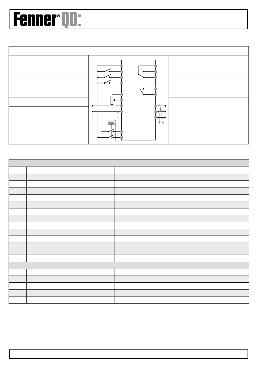
4.8 Control Terminals Connection Diagram
Control Terminal Designations and Default Function Assignments
+24 Volt Control Circuit Supply or
external 24 Volt Power Supply
Programmable Relay Output
Drive Healthy
Run / Enable
Fwd/Reverse
Analog/Preset Speed
Programmable Relay Output
Drive Running
Programmable Analog Inputs Programmable Analog Output
Output Speed
Output Current
External Safety Circuit for Safe Torque
Off Function
4.9 Control Terminal Connections
Main Terminal Strip
1 +24V + 24V User Output (Input) 100mA User Output or +24V back up supply
2 DI 1 Input 1 Digital 8 – 30 Volt DC
3 DI 2 Input 2 Digital 8 – 30 Volt DC
4 DI 3 Input 3 Digital 8 – 30 Volt DC
5 +10V +10 Volt user output 10mA for user potentiometer
6 AI 1 Input 4 Digital 8 - 30V DC / Analog Input 1,-10 to +10V, 0 / 4 to 20mA
7 0V 0 Volt Common
8AO1 Output 1 1st Analog / Digital Output, 0 to 10V, 4 to 20mA or +24VDC Digital
9 0V 0 Volt Common
10 AI 2 Input 5 Digital 8 - 30V DC / Analog Input 2, 0 to 10V, 0 / 4 to 20mA or Motor PTC
11 AO2 Output 2 2nd Analog / Digital Output, 0 to 10V, 4 to 20mA or +24VDC Digital
12 STO+ Drive hardware inhibit “Safe” 24V input - must be linked to ext +24 Volt (18 – 30 Volt) DC to
enable power stage
13 STO- Inhibit 0V input 0V return for the 24V “Safe” (STO)
Additional Terminal Strip
14 RL1-C Relay output 1 common Relay contacts, 250V AC, 30V DC, 5A
15 RL1-NO Relay output 1 NO Relay contacts, 250V AC, 30V DC, 5A
16 RL1-NC Relay output 1 NC Relay contacts, 250V AC, 30V DC, 5A
17 RL2-A Relay output 2 common Relay contacts, 250V AC, 30V DC, 5A
18 RL2-B Relay output 2 NO Relay contacts, 250V AC, 30V DC, 5A
AO2
0V
AO1
RL2-NO
RL2-C
RL1-C
RL1-NO
RL1-NC
STO+
STO-
0V
AI2
AI1
+10V
+24V
DI1
DI2
DI3
ııııııııııııııııııııııııııııııııııııııııııııııııııııııııııııııııııııııııııııııııııııııııııııııııııııııııııııııııııııııııııııııııııııııııııııııııııııııııııııııııııııııııııııııııııııııııııııııııı
www.fptgroup.com
HVAC
Installation & Operating Instructions
Page 19
5. Managing the Keypad
The drive is configured and its operation monitored via the built in keypad and display.
IP20 Drives: IP20 rated drives are supplied with a 7 segment LED display and a five button keypad
IP55 & IP66 Drives are supplied with an OLED multi-line text display and a seven button keypad
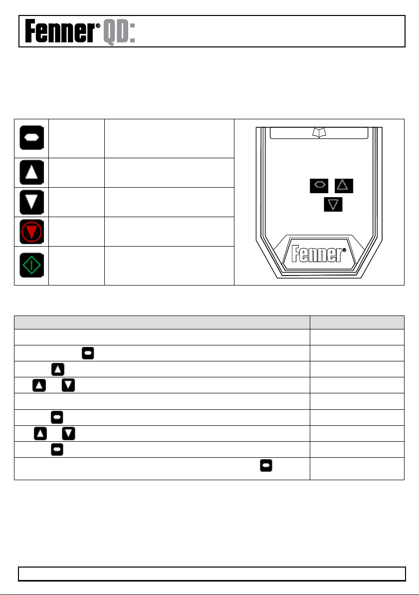
5.1 Keypad layout and Function - Standard LED Keypad (IP20 Drives)
NAVIGATE
Used to display real-time informa-
tion, to access and exit parameter
edit mode and to store parameter
changes
UP
Used to increase speed in real-time
mode or to increase parameter
values in parameter edit mode
DOWN
Used to decrease speed in real-time
mode or to decrease parameter
values in parameter edit mode
RESET/STOP
Used to reset a tripped drive. When
in keypad mode is used to Stop a
running drive
START
When in keypad mode, used to start
a stopped drive to reverse the direc-
tion of rotation if bidirectional keypad
mode is enabled
5.2. Changing Parameters - Standard LED Keypad (IP20 Drives)
Procedure Display Shows...
Power on Drive stop
Press and hold the for >2 seconds P1-01
Press the key P1-02
The and can be used to select the desired parameter P1-03
Select the required parameter, e.g. P1-02 P1-02
Press the button 0.0
Use the and keys to adjust the value e.g. set to 10 10.0
Press the key P1-02
The parameter value is now adjusted and automatically stored. Press the key for
>2 seconds to return to operating mode
stop

ııııııııııııııııııııııııııııııııııııııııııııııııııııııııııııııııııııııııııııııııııııııııııııııııııııııııııııııııııııııııııııııııııııııııııııııııııııııııııııııııııııııııııııııııııııııııııııııııı
www.fptgroup.com
HVAC
Installation & Operating Instructions
Page 20
5.3 Accessing and Changing Parameter Values
Function When Display
Shows
Press Result Example
Fast selection of
Parameter Groups
Note: Parameter
Group Access must
be enabled
P1-14=101
Px-xx The next highest
Parameter group is
selected
Display shows P1-10
Press
Display shows P2-01
Px-xx The next lowest
Parameter group is
selected
Display shows P2-26
Press
Display shows P1-01
Select lowest Group
Parameter
Px-xx The first parameter of
a group is selected
Display shows P1-10
Press
Display shows P1-01
Set Parameter to
minimum value
Any numerical value
(whilst editing a
parameter value)
The parameter is set
to the minimum value
When editing P1-01
Display shows 50.0
Press
Display shows 0.0
Adjusting individual
digits within a
parameter value
Any numerical value
(whilst editing a
parameter value)
Individual parameter
digits can be adjusted
When editing P1-10
Display shows 0
Press
Display shows .0
Press
Display shows 10
Press
Display shows .1 0
Press
Display shows 1 10
etc
+
+
+
+
+
+
+
+
+
+
+
Table of contents
Popular DC Drive manuals by other brands

Franklin Electric
Franklin Electric MONODRIVE UTILITY UT3W owner's manual

East Coast Datacom
East Coast Datacom ALD-19.2 installation guide

Motor City Wash Works
Motor City Wash Works ROCKRHYD Series installation manual

LSIS
LSIS S100 Series quick start guide

Bosch
Bosch Active Line Plus BDU 350 Original operating instructions

Eaton
Eaton PowerXL DM1 Series quick start guide

Siemens
Siemens SINAMICS V20 Series Easy start guide

Allen-Bradley
Allen-Bradley PowerFlex 520 Series Original instructions

Rockwell Automation
Rockwell Automation Allen-Bradley PowerFlex 7000 user manual

Veichi
Veichi AC80T manual

REDEX ANDANTEX
REDEX ANDANTEX Z Series Setup and maintenance instructions

Johnson Controls
Johnson Controls VFD Series Installation & operation


