Easy Start Guide
Page 9
This guide has been produced by The Inverter Drive Supermarket Ltd.
All content, including but not limited to graphics, text and procedures copyright The Inverter©
Drive Supermarket and must not be reproduced or altered without prior written permission.
8. How to connect and configure a Potentiometer
for remote speed control
Set to to allow access to extended parameters.2
Set value to for Analog as speed setpoint (select index first if prompted).2 in000
8.1 Parameters to change for remote Potentiometer speed control
If speed control via the up and down keys is
unsuitable for the application, a remote
Potentiometer can be used instead.
This provides the benefit of allowing motor
speed to be controlled from a more convenient
location such as a cabinet door (if the V20 is
cabinet-mounted) or on the machine itself.
A Potentiometer of more than 5kOhm rating
should be used eg. .10kOhm
The number of turns depends on the
application but both single turn and ten turn
Potentiometers are available from The Inverter
Drive Supermarket at InverterDrive.com.
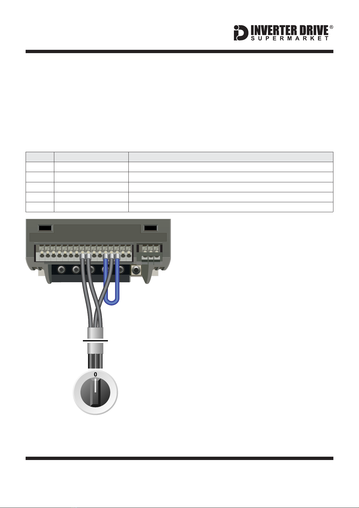
8.2 Connecting the Potentiometer
A wiring diagram is shown in the illustration
opposite. The most important connection at
the Potentiometer end is the centre terminal or
“wiper”. The wiper will output a variable voltage
between 0 and 10 volts and should be
connected to the AI1 terminal on the Inverter. It
is this voltage which provides the speed signal
with 0V being slowest and 10V fastest.
The default output frequency at 10V is
determined by parameter P2000. The default
output frequency at 0V is determined by P0758
as a percentage of P2000.
If the rotation of the Potentiometer is the
opposite to that required (ie. turn anti-
clockwise to increase speed instead of
clockwise) reverse connections 10V and 0V.
Use screened cable between the Inverter and
Potentiometer. To minimise electromagnetic
interference, ensure the screen is grounded.
2
1
3
Screened
Cable
10kOhm
Potentiometer
[Order Code 21302]
Screen to
Earth Terminal
Siemens V20 Series Inverter
W DC- DC+
DI 1
DI 2
DI 3
DI 4
DI C
24V
0V
D0 1+
DO 1-
DO2
NC
DO2
NO
DO2
C
UV
10V
AI 1
AI 2
AO 1
0V
P+
N–
12 3