Vintage Air 491252 User manual

an ISO 9001:2015 Registered Company
Streamline
3-Knob Horizontal Wide Panel, Black Anodized
491252
901356 REV A 02/27/19, PG 1 OF 8
18865 Goll St. San Antonio, TX 78266
Phone: 800-862-6658
Sales: [email protected]
www.vintageair.com

2
www.vintageair.com
901356 REV A 02/27/19, PG 2 OF 8
Cover..................................................................................................................................
Table of Contents.................................................................................................................
Packing List/Parts Disclaimer..................................................................................................
Control Panel Dimensions and Installation................................................................................
Control Panel Installation (Cont.)............................................................................................
Wiring Diagram....................................................................................................................
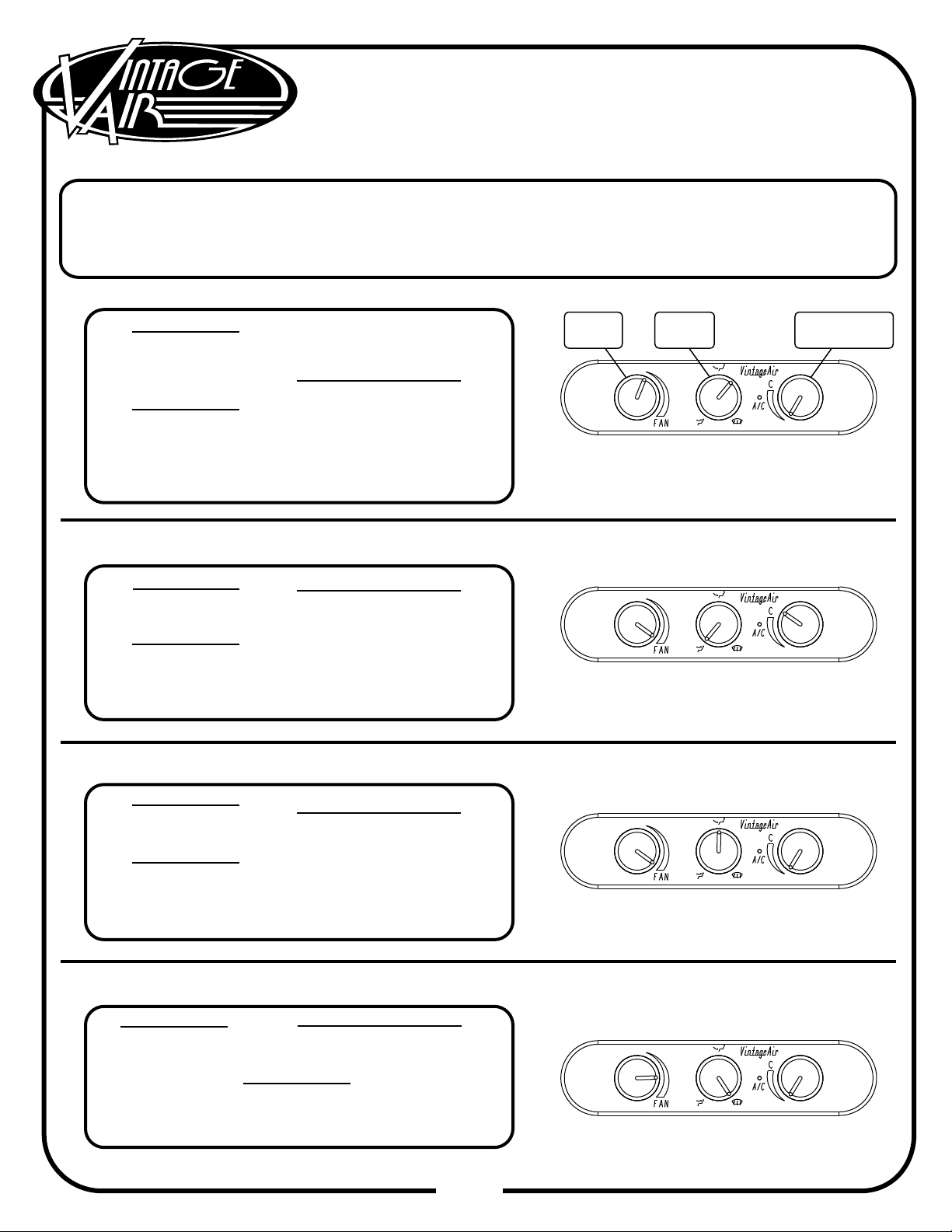
Operation of Controls............................................................................................................
Packing List.........................................................................................................................
1
2
3
4
5
6
7
8
Table of Contents
Important Notice—Please Read
For Maximum System Performance, Vintage Air Recommends the Following:
Evacuate the system for 35-45 minutes with system components (Drier, compressor, evaporator and
condenser) at a temperature of at least 85° F. On a cool day, the components can be heated with a
heat gun OR by running the engine with the heater on before evacuating. Leak check and charge to
specifications.
The Proper Amount of Refrigerant is Critical to Proper System Operation.
Vintage Air Recommends Our System be Charged by Weight with a Quality
Charging Station or Scale.
_
Service Info:
Refrigerant Capacity for Vintage Air Systems:
(For other systems, consult manufacturer’s guidelines)
R134a System
Charge with 1.8 lbs. (1 lb., 12 oz.) of refrigerant.
Lubricant Capacities:
New Compressor—No Additional Oil Needed.
Used Compessor—Consult Vintage Air.
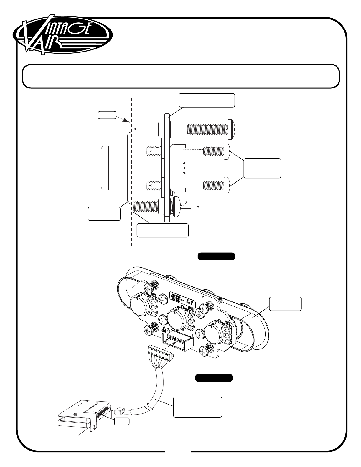
This control panel is designed to only work with a Gen IV evaporator unit equipped with a 246204-PUA
ECU. Please conrm that your unit has the proper ECU prior to installing the control panel as shown
below. A replacement ECU can be purchased from Vintage Air if needed.

3
www.vintageair.com
901356 REV A 02/27/19, PG 3 OF 8
Packing List:
Control Panel Kit (491252)
Streamline 3-Knob
Horizontal Wide, Black Anodized
No.
1.
2.
Qty.
1
1
Part No.
491253
232007-VUR
Description
Streamline 3-Knob Horizontal Wide Control Panel (Black Anodized)
Gen IV Universal Control Harness
** Before beginning installation, open all packages and check contents of shipment.
Please report any shortages directly to Vintage Air within 15 days. After 15 days,
Vintage Air will not be responsible for missing or damaged items.
12
NOTE: Images may not depict actual parts and quantities.
Refer to packing list for actual parts and quantities.

4
www.vintageair.com
901356 REV A 02/27/19, PG 4 OF 8
Control Panel Dimensions
Control Panel Installation
Select a suitable location for the control panel, considering heater control valve location, wiring harness length
and operator convenience.
After selecting a location for the control panel, mask the area 2 ½” (tall) x 6 ½” (wide).
Using the dimensions provided above, mark or scribe the control panel opening location onto the dash.
When you are certain that your dimensions and markings are correct, cut the dash to make the control
panel opening. NOTE: Measure twice. Cut once. This opening MUST be a precise t. Cut the opening
undersize, and then le to t. The mounting screws only hold the panel against the dash. They do
not locate the panel laterally. If the opening is oversized, the panel may shift during use.
Install the control panel face through the opening in the dash. Place the control panel PC board assembly
behind the dash, and secure it to the control panel face using the (4) 8-32 x 3/8” screws (See Figures 1 &
2, below, and Figure 3, Page 5). NOTE: When tightening the control panel mounting screws, hand
tighten until the screw contacts the back side of the dash. Then, using a screwdriver, tighten an
additional 1/2 turn. Do not over tighten, as this may cause damage to the PC board or the dash.
1.
2.
3.
4.
(4) Control Panel
Mounting Screws
Control Panel PC
Board Assembly
Control
Panel Face
Figure 1
Figure 1
5.318”
4.250”
1.068”
Opening
in Dash
(4) Control Panel
PC Board Mounting
Screws
Figure 2
Level This Line
Thread Into Back
Side of Control
Panel Face

5
www.vintageair.com
901356 REV A 02/27/19, PG 5 OF 8
Control Panel Installation (Cont.)
Figure 3
Rear View
Side View
Plug the control panel wiring harness into the control panel and the ECU on the evaporator (See Figure 4,
below).
Wire according to the wiring diagram on Page 6.
5.
6.
Figure 4
Control
Panel Face
Dash
Control Panel
PC Board Assembly
Thread Into
Control
Panel Face
Snug Against
Back Side of Dash
Control
Panel Face
Gen IV Universal
Control Harness
232007-VUR
ECU

6
www.vintageair.com
901356 REV A 02/27/19, PG 6 OF 8
WHT/GRN
WHT/YEL
WHT/RED
RED
WHT
BACKLIGHT NEG
FAN WIPER
MODE WIPER
TEMP WIPER
5V-SW
GND
BACKLIGHT POS
AC ANNUNCIATOR
PRE-WIRED
GEN IV WIRING DIAGRAM
REV E, 10/6/2017
GEN IV ECU
PROGRAM
Wiring Diagram
TEMP
MODE
FAN
A/C
(IF USED)
232007-VUR
232002-VUA
** CIRCUIT
BREAKER
30 AMP
*** WIDE OPEN
THROTTLE
SWITCH
(OPTIONAL)
* DASH LAMP
(IF USED)
Dash Lamp Is Used Only With Type 232007-VUR Harness.
Warning: Always Mount Circuit Breaker As Close to the Battery As Possible. (NOTE: Wire Between
Battery and Circuit Breaker Is Unprotected and Should Be Carefully Routed to Avoid a Short
Circuit).
Wide Open Throttle Switch Contacts Close Only at Full Throttle, Which Disables A/C
Compressor.
JF8
BLK
ORA
TAN
VIEWED FROM WIRE SIDE
*
**
***
HEATER
CONTROL VALVE

7
www.vintageair.com
901356 REV A 02/27/19, PG 7 OF 8
Operation of Controls
Adjust to desired
speed.
Blower Speed
Adjust to desired
speed.
Adjust to desired
mode position
(DASH position
recommended).
Adjust to desired
speed.
Adjust to DEFROST position for maximum defrost, or
between FLOOR and DEFROST positions for a bi-level
blend (Compressor is automatically engaged).
Adjust to desired
temperature.
For A/C operation, adjust to
coldest position to engage
compressor (Adjust between
HOT and COLD to reach
desired temperature).
A/C Operation
Heat Operation
Defrost/De-fog Operation
On Gen IV systems with three lever/knob controls, the temperature control toggles between heat and A/C
operations. To activate A/C, move the temperature lever/knob all the way to cold and then back it off to the desired
vent temperature. For heat operation, move the temperature lever/knob all the way to hot and then adjust to the
desired vent temperature. The blower will momentarily change speed, each time you toggle between operations, to
indicate the change.
Blower Speed
Blower Speed
This lever/knob controls
blower speed, from
OFF to HI.
This lever/knob controls
the mode positions,
from DASH to FLOOR
to DEFROST, with a
blend in between.
This lever/knob controls
the temperature,
from HOT to COLD.
Blower Speed
Mode Control
Temperature Control
Temperature Control
Temperature Control
Temperature Control
Mode Control
Mode Control
Mode Control
For maximum heating, adjust
to hottest position (Adjust
between HOT and COLD to
reach desired temperature).
Adjust to desired
mode position
(FLOOR position
recommended).
Blower
Speed Mode
Control Temperature
Control

8
www.vintageair.com
901356 REV A 02/27/19, PG 8 OF 8
Packing List:
Control Panel Kit (491252)
Streamline 3-Knob
Horizontal Wide, Black Anodized
No.
1.
2.
Qty.
1
1
Part No.
491253
232007-VUR
Description
Streamline 3-Knob Horizontal Wide Control Panel (Black Anodized)
Gen IV Universal Control Harness
12
NOTE: Images may not depict actual parts and quantities.
Refer to packing list for actual parts and quantities.
Checked By:
Packed By:
Date:
Table of contents
Other Vintage Air Control Panel manuals
Popular Control Panel manuals by other brands

Truma
Truma Panel BC (616) Operating instructions & installation instructions

Sony
Sony MKS-R3210 operating instructions

Schaudt
Schaudt DT 220 B instruction manual

Intermatic
Intermatic P1353ME Installation, operation & service manual

Dimplex
Dimplex WPM Econ5S installation instructions

Comelit
Comelit Maxi Manager operating manual