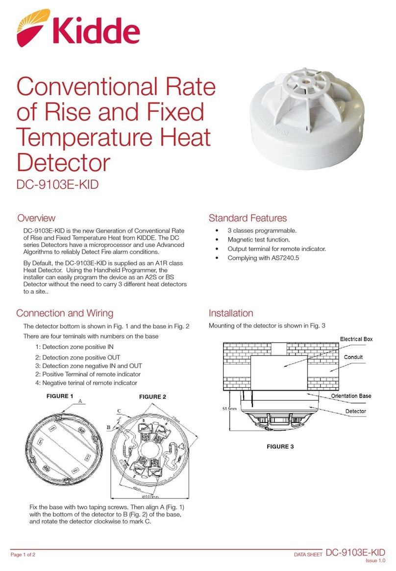
Fenwal F1H-RYW1 Administrator Guide

Page 1
F1H-RYW1
Operation Instruction Manual
ES1255 K2
Thank you for purchasing this product.
In this manual, we have shown the important notice in
order for you to use the device just and the method of
handling this system.
In additional to you read this manual well before the
utilization, understanding well, and use.
After you read, in the place where it seen with it is seen
with anytime, please to be sure to keep.

730110 K0
2
ES1255
Page
Table of contents
1. Safety Instructions ................................................................................................................................ 3
2. Name and Function of each section ........................................................................................................ 4
3. Install .................................................................................................................................................. 5
4. Specification ...................................................................................................................................... 8
5. Maintenance and Inspection ................................................................................................................ 10
6. Disposal............................................................................................................................................. 13
7. Support .............................................................................................................................................. 13

730110 K0
3
ES1255
Page
1. Safety Instructions
・This smoke detector has the ability to transfer information outputs and alarm status indicators to detect
smoke.
・Before the using, read this chapter and use correctly.
・The contents which it occurs when you handle erroneously are divided in two of “warning” and “caution”.
This division states clearly the size and impendence of the harm and the damage.
・Please keep below rules for safety.
・Guarantee
[A term of a guarantee]
In regard to the guarantee of this product, the designated payment of the order main thing after the paying
1 years you guarantee first only the breakdown which occurs in the normal busy condition which you
follow the instruction manual.
[Guarantee range]
In regard to the breakdown which it occurs in this product with the criticism of payment person side
during the above-mentioned guarantee period, it does returns repair in the responsibility of payment
person side. However, when it corresponds next, you exclude from the object of this guarantee.
1) Fire, earthquake and the damage by wind and flood, breakdown and the loss by the thunderbolt
and other natural disasters etc.
2) After the shipping, transporting and moving and falling etc at your corporation, breakdown and
the loss with inadequate handling.
3) When cause of breakdown due to the reason other than the payment item.
4) Error in regard to use of the consumer, breakdown and the loss with repairing, remodeling other
than our company and error connecting.
Furthermore, the guarantee referred to here being something which means the guarantee of the payment
item single unit, pardons the damage which is induced by the breakdown of the payment item.
The Warning symbol is
used to indicate situations and conditions that can cause
operator serious injury and/or equipment damage.
The
Caution
symbol is
used to indicate situations and conditions that can cause
operator injury and/or equipment damage.
!
Warning
・Do not disassemble a detector. It causes trouble.
・Do not remove a detector, Fire can not be detected.
・Do not use detector which have impacted. And also do not paint or cover a
detector.
・Do not soak a detector in water, and do not put a detector into water. It causes
electric shock.
・Do not use the method that not listed in this manual, It causes trouble.
・This system only tells the outbreak of a fire. This system is not Fire prevention
systems. And Fire extinguishing system.
・Do not use at the place where it exceeds environmental specification. It causes
trouble.
・Do not put heat source under the detector.
Caution
!
!
Warning
Caution
!

730110 K0
4
ES1255
Page
2. Name and Function of each section
Detector
Mounting Base
State Indication LED
・Normal supervision:10 seconds interval
・Alarm mode:1 seconds interval
・Trouble mode:Off (not blinking)
Power Supply &
Signal output connector
Guide of installation
Insert Terminal 3, 4
Smoke Air flow
Insert Terminal 1, 2

730110 K0
5
ES1255
Page
3. Install
3.1. Install of Smoke Detector
Smoke detectors should be installed in order to detect following place.
・The flow of smoke into position
・Fans forced to inhale position
When you use smoke detector in a fast wind speed, it is necessary that the smoke is ongoing around
detector. Please be careful.State Indication LED Address number should be placed below or sideways
・The smoke detector detects a scattered light by smoke particles optically.
And that detects a large amount of dust and steam too.
Please install correct location.
・Do not use at the place where it exceeds environmental specification. It
causes trouble.
・Do not install wrong location. The smoke detector cannot detect a smoke.
・Be sure to install the detector away from sources of electrical noise such as
high voltage and high current switches.
[Isolation from electric noise source such as power line]
The signal conductor which is connected to the detector, please wires over
20cm
separating from the power line.
Case it is not possible, please pass in the metallic conduit which the power line is
grounded.
・Do not disassemble a detector. It causes trouble.
・Do not remove a detector, Fire can not be detected.
・Do not use detector which have impacted. And also do not paint or cover a
detector.
・Do not wiring while power is on. It causes electric shock and detector troubles.
Caution
!
Caution
!
!
Warning

730110 K0
6
ES1255
Page
3.2. Method of installation
(1)Names of parts mounting base is as follows.
(2)Please install a Mounting Base to “install holes” with two screws M3 which is more than 15mm
length.
(3)Please put both insert guides together, and insert Terminal and Attachment of Detector into Mounting
Base. And Turn a Detector Clockwise until make a sound with "a snick".
・Incorrect loading of the equipments can cause a malfunction, failure or drop.
・Tighten the screw in the specified torque range. (torque 0.5N・m: Reference
value)
・Under tightening can cause a drop, short circuit or malfunction.
・Over tightening can cause a drop, short circuit or malfunction due to damage to
the screw or he equipments and
malfunction and fire.
・Put Insert guides, Detector Terminal and Attachment together correctly.
It causes trouble.
・Do not turning a detector too much. Also do not make a lack of insertion.
・Do not remove a detector, Fire can not be detected.
・Do not use detector which have impacted. And also do not paint or cover a
detector.
!
Warning
!
Warning

730110 K0
7
ES1255
Page
(4)Please insert the connector cable into the output connector.
・The connectors are polarized. Please make suitable polar insertion. And please
ensure that no loose insert. Loose or Force inserts failure can cause a fire.
・Please do not pull the connector strongly. It causes damage.
・Output relay is PhotoMOS relay. Insulation Test under DC24V between Relay
and Relay, Relay and Power supply.
・Do not place obstacle as wiring etc. near the slit of the detector. It will disturb
inflow of smoke.
・Please provide a dedicated power supply as much as possible.
・This Detector does not have over voltage protection device. Before using,
Please add an external over current circuit breaker.
・Smoke detectors are detecting light scattered by smoke particles in the optical.
When used in an environment that generated a large amount of water vapor and
particles of dust and smoke can not cause false alarms.
!
Warning
Caution
!

730110 K0
8
ES1255
Page
4. Specification
(1)
Name
:
Photoelectric Smoke Detector
(2)
Type
:
F1H
-
RYW1
-
xx
xx
x
①Sensitivity
②Type of Output
③Length of cable
Standard setting F1H-RYW1-05BB2
Sensitivity 5%/m, Alarm Output B, Trouble Output B, Cable length 2m.
①Sensitivity:3%/m~10%/m(Value = 03~10)
Standard Setting is 5%/m.(Value=05)
②Type of Output:Type of Alarm & Trouble Output
Standard Setting is Alarm=B,Trouble=B.
(Value = BB)
③Length of cable:Cable Length 0=None,2=2m,5=5m。
Standard Setting is 2m. (Value = 2)
4.1. Electrical Specification
(1)
Rated Current
:
DC
3
0mA
(2)
Range of
Operating Voltage
:
DC10.0V~DC30.0V
Acceptable ripple voltage 300mVp-p
Power supply with connector cable.(See bellow(6))
(3)
Sensitivity
:
Depend on Type of Product. 5%/m(Nominal)
(4)
State Indication
LED
:
RED
LE
D
State of LED
Normal mode
10 second
s interval
A
larm
mode
1
second
s int
erval
T
rouble
mode
O
ff (not blinking)
Alarm will override trouble.
(5)
Output
:
Alarm, Trouble Relay Output
Capacity of Relay DC24V,0.5A Resistance loading
State depends on Type of relay.
Type Contact Normal
mode
Alarm
mode
Trouble
mode
Power
OFF
AA Alarm Open Close Open Open
Trouble Open Open Close Open
AB Alarm Open Close Open Open
Trouble Close Close Open Open
BA Alarm Close Open Close Open
Trouble Open Open Close Open
BB
(Standard)
Alarm Close Open Close Open
Trouble Close Close Open Open
・State of output will be normal about a second after power supply.
・Output relay is PhotoMOS relay.
・On resistance Max.0.7Ω.Off state leakage current 1μA.
・Insulation Test under DC24V between Relay and Relay, Relay and
Power supply.

730110 K0
9
ES1255
Page
(6)
Connector Cabl
e
of Power supply &
Output
:
Connector cable included.
Connector:JST SHR-06V 6pin
Cable:Temperature rating 80℃,Voltage rating 300V,AWG#28, UL1061
Length:Depend on Type of Product. Standard is 2m..
Connection Details
Pin № & Color
Power Operating Voltage
6
Blue - 5
White
Alarm 3
Orange - 4
Orange
Trouble 1
Brown - 2
Brown
(7)
Alarm
Restoration
:
Auto
Restoration
:When smoke disappear Automatically.
(8)
Self Check
:
Dirty, D
eterioration
(9)
Automatic test
function
:
Automatically sensitivity corr
ection is carried out once a day to
check sensitivity change of optical instruments by
environmental and annual deterioration. The detector becomes
trouble condition before exceeding correctable limit.
4.2. Mechanical Specification
(1)
External
:
Φ28×H57mm(Installation Base 10mm is contained)
(2)
Mass
:
Approx 25g(Installation Base is contained)
(3)
Main
Material
:
ABS resins
4.3. Environmental Specification
(1)
Operating
Temperature
Range
: -10℃~60℃
(2)
Storage
Temperature
Range
: -20℃~75℃
(3)
Operating
Humidity Range
: 30~85%RH Non condensing
(4)
Storage
Humidity Range
: 5~95%RH Non condensing
(5)
Resistance to
corrosion
:
N
o tolerance
t
o acid and alkaline.
Use the detector in an environment that meets the general specifications
contained in this manual. Otherwise it causes trouble and erroneous operation.
Working temperature and humidity will affect the life span of equipment.
Please consider derating and use.
!
Warning
Caution
!

730110 K0
10
ES1255
Page
5. Maintenance and Inspection
5.1. Daily Inspection
№
Item
Object
Content
Method
Judgment
Criteria
Treatment
1
Installation
Common
S
ecurely locked?
Move the
detector to
check.
The detector must
be installed
securely.
Retighten the
screws on the
base with proper
torque.
Obstacle
near the
inlet of detector?
Check
Visually
Obstacle must n
ot
be present.
Removed.
2
Appearance
Common
Adhesion of dirt
and foreign
matter?
Check
Visually
Dirt and foreign
matter must not
be present.
Removed and
Clean.
Damages?
Check
Visually
Damages must
not be present.
Change the
detector.
3
Wiring
Common
Damages or
Breakages?
Check
Visually
Damages must
not be present.
C
h
a
nge
the
connector cable.
Adhesion of dirt
and foreign
matter on the
connector?
Check
Visually
Dirt and foreign
matter must not
be present.
Removed and
Clean.
Looseness of
connectors
Move the
wire to
check.
Connectors must
not be loose
Change the
connector cable.
4
Behavior
Normal
supervision
Detector
State Indication
LED
Check
Visually
Blink 10 seconds
interval.
Check the State
Indication LED
behavior.
・Please do not touch the terminal while the unit is energized. It may get an electric
shock.
・Please do the cleaning and the increase tightening of the screw after the power
supply off. If not the power supply off, it may get an electric shock.
・Do not soak a detector in water, and do not put a detector into water.
・Under tightening can cause a drop, malfunction.
・Over tightening can cause a drop, malfunction due to damage to the screw or
equipments and malfunction.
・Please use the dry cloth or wring the water out tightly cloth for the cleaning.
・After Cleaning, Do not leave a foreign substance such as sawdust or wiring debris
on a detector. Such debris could cause erroneous operation.
・Do not clean with a solvent such as a ph-balanced detergent, Bleach, Benzene,
Thinner, Alcohol. It causes the detector surface is damaged.
!
Warning
Caution
!

730110 K0
11
ES1255
Page
5.2. Periodic Inspection
The items that must be inspected one or two times every 6 months to 1 year are listed below.
When the equipment is moved or modified, or layout of the wiring is changed, also perform this
inspection.
Do not needs to check smoke detect function with real smoke such as Tobacco, incense, etc. Because
this smoke detector has self check functions.
№
Item
Object
Content
Method
Judgment
Criteria
Treatment
1
Operating Temperature
Common
U
sed within the
specification?
Measure
with a
thermometer.
-10℃~60℃
Meets the
specification.
2
Operating Humidity
Common
U
sed within the
specification?
Measure
with a
hygrometer.
30~85%RH Non
condensing
Meets the
specification.
3
Atmosphere
Common
IS t
here volatile
or corrosive
gas?
Measure
corrosive
gas.
N
o tolerance
t
o
acid and alkaline.
Meets the
specification.
4
Power
Supply
Voltage
Common
U
sed within the
Power Supply
Voltage
specification?
Measure a
Power
Supply
voltage.
DC10.0V ~
DC30.0V
Meets the
specification.
5
Ripple Voltage
Common
U
sed within the
Ripple Voltage
specification?
Measure a
ripple
voltage.
30
0mV
p
-
p
Meets the
specification.
6
Installation
Common
S
ecurely
locked?
Move the
detector to
check.
The detector must
be installed
securely.
Retighten the
screws on the
base with proper
torque.
Obstacle
near
the inlet of
detector?
Check
Visually
Obstacle must not
be present.
Removed.
7
Appearance
Common
Adhesion of dirt
and foreign
matter?
Check
Visually
Dirt and foreign
matter must not
be present.
Removed and
Clean.
Damages?
Check
Visually
Damages must
not be present.
Change the
detector.
8
Wiring
Common
Damages or
Breakages?
Check
Visually
Damages
must
not be present.
Change the
connector cable.
Adhesion of dirt
and foreign
matter on the
connector?
Check
Visually
Dirt and foreign
matter must not
be present.
Removed and
Clean.
Looseness of
connectors
Move the
wire to
check.
Connectors must
not be loose
Change the
connector cable.
9
Behavior
Normal
supervision
Detector
State Indication
LED
Check
Visually
Blink 10 seconds
interval.
Check the State
Indication LED
behavior.
・Please do not touch the terminal while the unit is energized. It may get an electric
shock.
・Please do the cleaning and the increase tightening of the screw after the power
supply off. If not the power supply off, it may get an electric shock.
・
Do not soak a detector in water, and do not put a detector into water.
!
Warning

730110 K0
12
ES1255
Page
・Under tightening can cause a drop, malfunction.
・Over tightening can cause a drop, malfunction due to damage to the screw or
equipments and malfunction.
・Please use the dry cloth or wring the water out tightly cloth for the cleaning.
・After Cleaning, Do not leave a foreign substance such as sawdust or wiring debris
on a detector. Such debris could cause erroneous operation.
・Do not clean with a solvent such as a ph-balanced detergent, Bleach, Benzene,
Thinner, Alcohol. It causes the detector surface is damaged.
Caution
!

730110 K0
13
ES1255
Page
6. Disposal
This product is as general industrial waste disposal.
Disposal methods are specific criteria depending on each municipality.
7. Support
Please inquire about this product to Fenwal Controls of Japan Co., Ltd. Tokyo headquarters.
Fenwal Controls of Japan Co., Ltd.
1-5-10 Iidabashi Chiyoda Tokyo, 102-0072 Japan
Tokyo headquarters: +81-3-3237-3565
警告
注意
警告
警告
警告
警告
注意
警告
Table of contents
Other Fenwal Security Sensor manuals
Popular Security Sensor manuals by other brands
CoCo
CoCo APIR-2150 Quick installation guide
Xulux
Xulux BT-PIR108 Install manual

First Alert
First Alert Radon RD1 Product specifications
System Sensor
System Sensor DH400 Installation and maintenance instructions
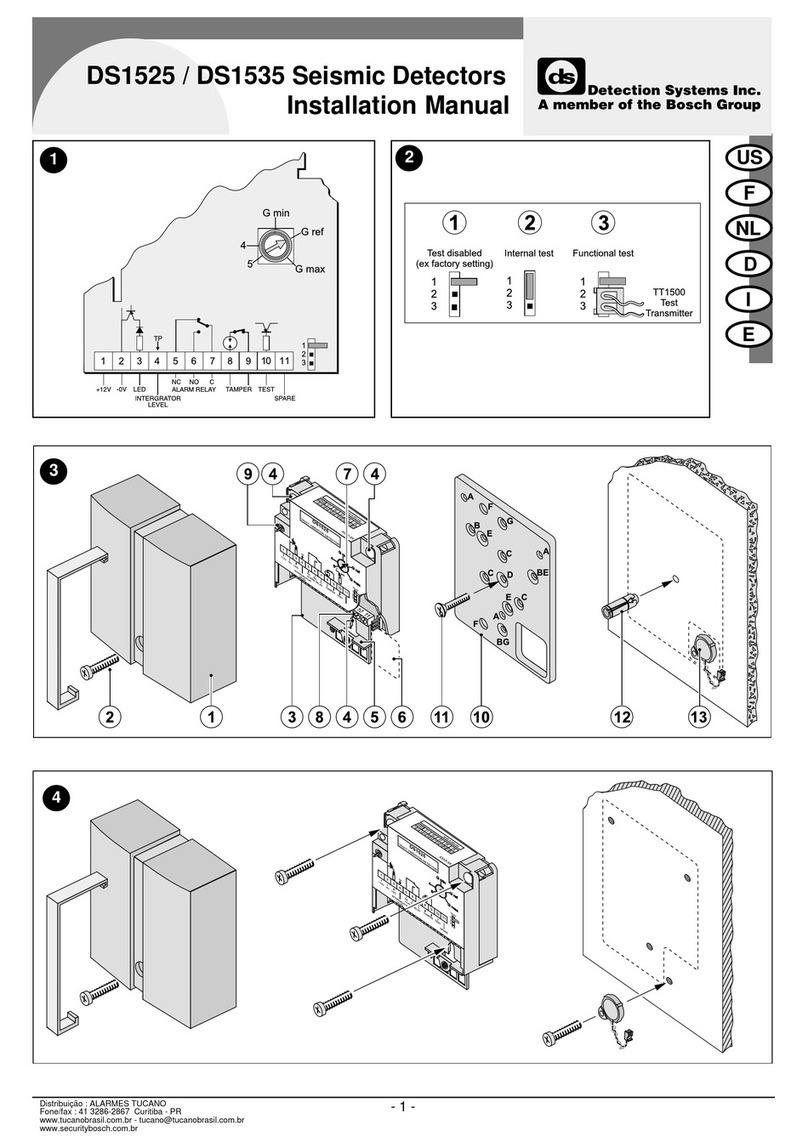
Detection Systems
Detection Systems DS1525 installation manual

Fisher Research Labs
Fisher Research Labs XLT-100 operating manual
