FERMOD KIT 5010 Guide

Kit5010ExpSécu_Elec-A
1
KIT 5010
Pour systèmes Fermatic manuels :
For manual Fermatic systems:
2120 / 2130 / 2150 - 2320 / 2420
3430 / 3530 / 7530
01/2016
R
Notice d’installation électrique / Mounting Electric part
NMkit5010ExpSécu_Elec-A
Cette notice comporte les instructions d'installation, d'utilisation et de maintenance.
Nous vous conseillons de la lire attentivement, et de la mettre à disposition de l'utilisateur.
This instructions manual includes the mounting, utilization and the maintenance instructions. We recommend to read this carefully and to place it at the user’s
disposal. The english version of our general conditions of sales and mounting instructions are not binding, and are only given for information purposes.
Only the french version can be used in case of legal action.
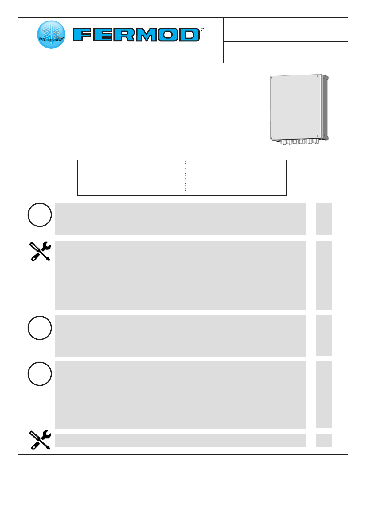
Alimentation : 220-240V AC
50/60 Hz monophasé
Puissance moteur : 370W
Power supply : 220-240V AC
50/60 Hz monophase
Motor power : 370W
i
i
i
p.2
p.2
p.3
p.3
p.7
p.9
p.10
p.10
p.12
p.17
p.19
p.19
p.19
p.19
p.20
p.20
p.20
p.20
p.21
p.21
p.21
p.22
1 - Informations générales / General informations............................................
2 - Caractéristiques du produit / Characteristics...............................................
3 - Précautions de montage / Mounting precautions........................................
4 - Cablage / Wiring...............................................................................................
5 - Sécurité horizontale / Horizontal safety device............................................
6 - Montage de la bordure passive / Passive edgemount security..................
7 - Paramétrage / Parameters.............................................................................
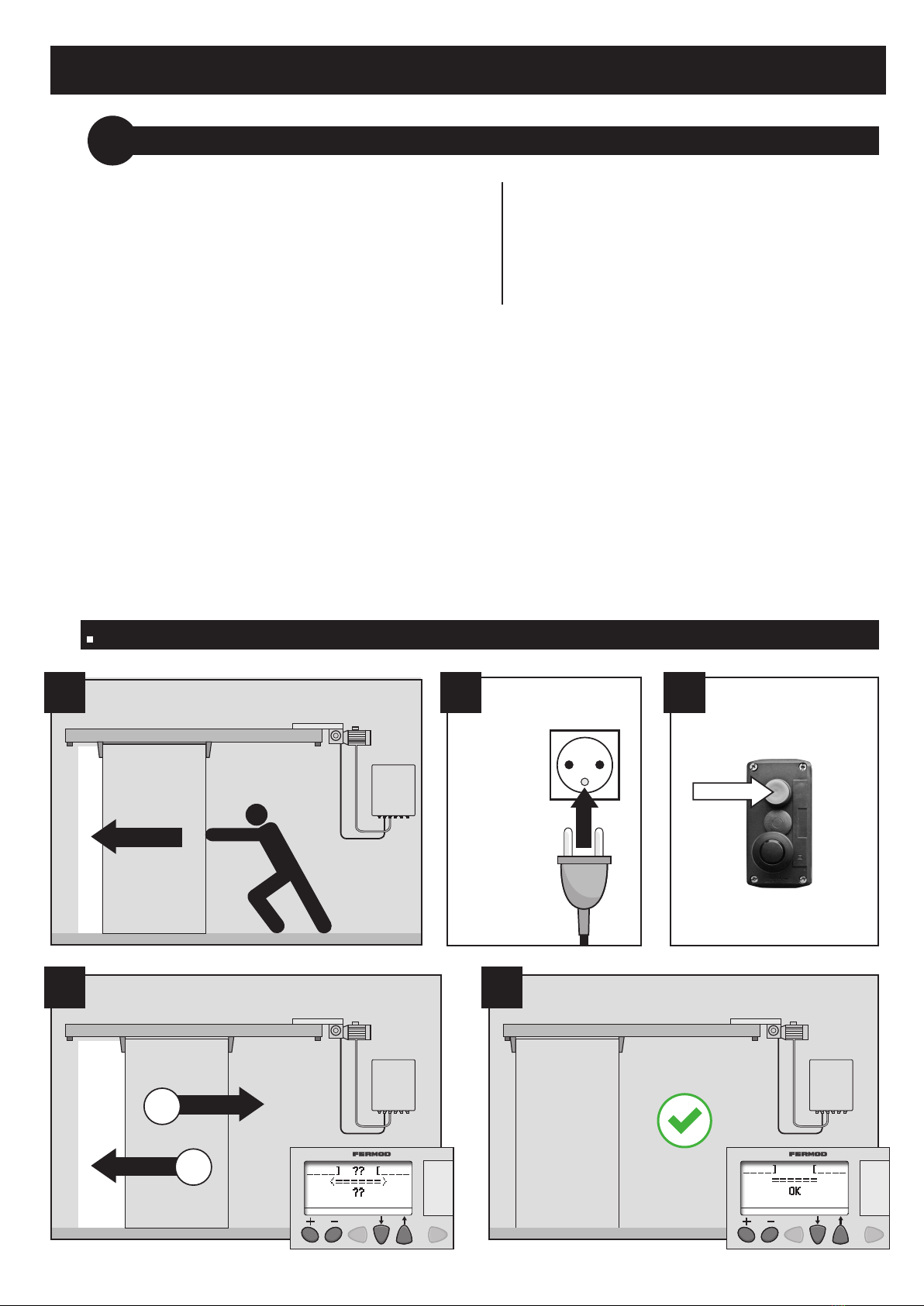
7.1 - Initialisation/1ère mise sous tension / Initialization/First power on............
7.2 - Utilisation de l’afcheur / Control keyboard using.....................................
7.3 - Codes information / Information codes......................................................
8 - Fonctions disponibles / Available functions...................................................
8.1 - Fonction verrouillage / Lock function.........................................................
8.2 - Commande d’arrêt / Stop command..........................................................
8.3 - Détection incendie / Fire detection............................................................
9 - Utilisation / Using..............................................................................................
9.1 - Utilisation prévue / Normal using...............................................................
9.2 - Risques consécutifs à des actions... / Risks following intentional acts..................
9.3 - Etiquettes d’identication / Identication stickers......................................
9.4 - Nettoyage / Cleaning.................................................................................
10 - Maintenance......................................................................................................
11 - Mise au rebut / Scrapping................................................................................
12 - Fonctionnement anormal / Malfunctioning...................................................

Kit5010ExpSécu_Elec-A
2
1 - INFORMATIONS GENERALES / GENERAL INFORMATIONS
Ce matériel doit être installé en respectant nos notices de montage et les indications complémentaires ci-après.
L’installation doit être réalisée conformément aux réglementations en vigueur dans le pays d’installation.
Si vous souhaitez un Kit 5010 répondant aux normes CE, merci de nous consulter.
If you need a Kit 5010 complying with the European Directives and Standards, please consult us.
This material must be installed as per our mounting instructions and the following instructions.
The installation must be realised in accordance with local regulations.
2 - CARACTERISTIQUES DU PRODUIT / CHARACTERISTICS
Alimentation
Power supply
220-240V AC 400W Mono
50/60 Hz
Puissance moteur
Motor power 370W
Classe d'étanchéité du moteur
Protection of the motor IP 55
Classe d’étanchéité du coret
Protection of the command box IP 65
Température d’utilisation
Using temperature -30°C +45°C *
*pour les températures négatives voir l’option Basse Température - notice séparée
*For negative temperature see «option for minus temperature»
Separate mounting instructions
Le kit automatique électronique 5010 dispose de 3 modes de fonctionnement :
The automatic electronic kit 5010 has 3 function modes:
Temporisé / Timer mode
Standard / Standard mode
Pression maintenue à l’ouverture et à la fermeture / «Press and hold to open/close the door» mode
Il possède un verrouillage intégré (qui ne remplace pas l’utilisation d’une serrure) et peut être équipé de
sécurité horizontale ou verticale (en fonction des réglementations en vigueur dans le pays d’installation).
It has an integrated lock (which does not replace the use of a mechanical lock), and can be equipped with
horizontal or vertical safety device (according to the regulations that apply in the country of installation).
Modes de fonctionnement / Function modes
Options spéciques / Options
Sécurité horizontale ou verticale (en fonction des réglementations en vigueur dans le pays d’installation)
Feu clignotant
Nous consulter pour toute demande spécique (bordure résistive, tirette...).
Horizontal or vertical safety device (according to the regulations that apply in the country of installation)
Flashing light
Please contact us for other options (resistive edgemount, pull cord...).
! !

Kit5010ExpSécu_Elec-A
3
Chauage (option)
Heating element
(option)
Acheur
Control keyboard
Disjoncteur
Circuit breaker
Carte alimentation
Power supply card
Carte moteur
Motor card
238
320
Longueur des câbles : 2m
Cables length: 2m
!
Ø4
- Réseau électrique : 220-240V AC - 50/60 Hz - L+N+Terre.
- Section du câble d’alimentation : 3G2,5 mm².
- Raccorder chaque kit à une ligne d’alimentation dédiée et protégée par un disjoncteur courbe D.
- Electrical network: 220-240V AC - 50/60 Hz.
- Connection cable section : 3G2,5 mm².
- Connect each Kit to a dedicated power line protected by a circuit breaker D curve.
!
3 - PRECAUTIONS DE MONTAGE / MOUNTING PRECAUTIONS
Veuillez respecter les réglementations en vigueur dans le pays d’installation.
Les points suivants doivent être vériés :
- Vérier les conditions climatiques de l’environnement. Pour les températures inférieures à -10°C, le
coret est spécique.
- L’adéquation entre le kit automatique à installer et le système manuel utilisé.
Veuillez suivre toutes les instructions de la notice.
Please respect the regulations that apply in the country of installation.
- Check the temperature of the environment. For temperatures lower than –10°C, a low temperature
command box is required.
- Check the compatibility between the Automatic Kit to be installed with the Fermatic Manual System.
Please refer to our mounting instructions.
4 - CABLAGE / WIRING
Coret électrique / Command box
M10

Kit5010ExpSécu_Elec-A
4
!
Raccordement moteur et codeur / Motor and encoder connection
Moteur (cable gris/2m)
Motor (grey cable/2m)
Codeur (cable noir/2m)
Encoder (black cable/2m)
Rallonge de câble 5m (2 rallonges bout-à-bout maxi)
Extension cable 5m (maxi 2 extensions endwise)
Perçage Ø 20mm mini pour passer les connecteurs
Drilling Ø 20mm mini to pass the connectors
Tube Ø 20mm minimum pour passer les câbles
Use tube Ø 20mm mini to pass the cables
OPTION
i
M10
M10
M6
M6
Vue arrière
Back view
Détrompeurs
Oriented slots
Couper impérativement l’alimentation avant d’intervenir sur le moteur
Absolutely cut the power supply before disconnecting the motor

Kit5010ExpSécu_Elec-A
5
Câblage carte interface / Interface card wiring
1314 1314
18 19
2
2
2222
3
3
6
2
2
5
4
1
16 17
15
14
13121110
9
8
7
1
1
1
43
1 2
43
18 3
16 8
1 2
C
43
1 2
43
1 2
18
319
DD
A
E
B
E
B
Ouverture totale
Total opening Ouverture totale
Total opening
Ouverture totale
Total opening
Ouverture partielle
Partial opening
Ouverture partielle
Partial opening
PE PE
9
A
A
Commande ouverture totale 1/2
ou pression maintenue (bouton poussoir)
Total opening command 1/2
or press and hold command (push-button) Toutes les commandes d’ouverture doivent être
de type à impulsion (sinon la porte reste ouverte
tant que le contact est actif)
All the opening commands must be impulse model
(otherwise the door remains open as long as
the contact is active)
B
Commande ouverture partielle 1/2
ou pression maintenue (bouton poussoir)
Partial opening command 1/2
or press and hold command (push-button)
C
Commande ouverture totale 1/2
(tirette, radar, boucle magnétique...)
Total opening command 1/2
(pull cord, radar, magnetic loop...)
DArrêt 1/2 (contact maintenu)
Stop 1/2 (hold-on contact) Pour câbler les commandes
d’arrêt, enlever le shunt
correspondant
Remove the corresponding shunt
to wire the stop commands
Ne pas cabler un bouton
d’arrêt D sur les mêmes bornes
qu’un bouton E
Do not wire a stop button D in
the same connecting terminals
than a button E
EArrêt 1/2 (contact maintenu)
Stop 1/2 (hold-on contact)
!

Kit5010ExpSécu_Elec-A
6
Câblage des options / Options wiring
Raccordement secteur / Power supply connection
Non fournie
Not provided
N
L1
PE
= Neutre
Neutral
= Phase
= Terre
Earth
Alimentation secteur /
Power supply :
220-240V AC
50/60 Hz mono
AFeu clignotant 1/2
Flashing light 1/2
Ce sont les feux qui clignotent, pas leur information de commande
Information for ashing lights command doesn’t ash
BDétection incendie
Fire detection Contact maintenu
Enlever le shunt correspondant
Hold-on contact
Remove the corresponding shunt
CVerrou ou serrure
Lock
!
18
192
2
2
2
2
2
3
3
6
2
2
5
4
1
16
1715
14
13
12
11
10
9
8
7
1
1
1
CB
NNoir
Black
RRouge
Red
A
Se reporter à la notice séparée NMoptionsKit5010Exp pour le câblage des diérentes options.
Please see separate mounting instructions: NMoptionsKit5010Exp to wire the dierent options.
i
N
BLEU / BLUE
L1
VERT / JAUNE
PE
ORANGE
GREEN / YELLOW
R
N
3G2,5 mm

Kit5010ExpSécu_Elec-A
7
500
PORTE
DOOR
HUISSERIE
FRAME
Positionnement d’un simple
barrage horizontal
Single cell position
5 - SECURITE HORIZONTALE / HORIZONTAL SAFETY DEVICE
Montage cellule/réecteur - Cell/reector mounting
1
2
14
3
Appuyer
à fond / Push
Inverser le sens de la cellule selon le sens
d’ouverture de la porte
Reverse the direction of the cell according to
the opening side of the door
Vis Ø8
52
10
14
PORTE FERMEE
DOOR CLOSED
65 mini
Raccorder électriquement
la cellule
(voir page suivante)
Electrically connect the cell
(see next page)
3
5
H1
x
2
==
PORTE OUVERTE
DOOR OPEN
Kit5000CE_Elec-A
12
Câblage / Wiring
Couper
Cut
37 41
38 4240
39
33
34
35
36
B
H1
BN
BL
M
G
ORANGE
ALIGNEMENT OK
ALIGNMENT OK
Blanc / White
Bleu / Blue
Gris / Grey
Marron / Brown
Noir / Black
G
B
Bl
M
N
VERT / GREEN
ALIMENTATION OK
POWER SUPPLY OK
29 30 32
31
Retirer le shunt
Remove shunt
!
B
!
H1
Sens ouverture
Opening side
==
116 ==
Ø5,5
15
Point rouge
du faisceau
Red point
of the beam
PORTE OUVERTE
DOOR OPEN
Pour le câblage d’un double barrage horizontal (option) se reporter à la notice séparée :
Wiring double horizontal safety device (option): please see separate mounting instructions:
NMoptionsKit5000CE
i
4
4
Point rouge
du faisceau
Red point
of the beam
Kit5000CE_Elec-A
12
Câblage / Wiring
Couper
Cut
37 41
38 4240
39
33
34
35
36
B
H1
BN
BL
M
G
ORANGE
ALIGNEMENT OK
ALIGNMENT OK
Blanc / White
Bleu / Blue
Gris / Grey
Marron / Brown
Noir / Black
G
B
Bl
M
N
VERT / GREEN
ALIMENTATION OK
POWER SUPPLY OK
29 30 32
31
Retirer le shunt
Remove shunt
!
B
!
H1
Sens ouverture
Opening side
==
116 ==
Ø5,5
15
Point rouge
du faisceau
Red point
of the beam
PORTE OUVERTE
DOOR OPEN
Pour le câblage d’un double barrage horizontal (option) se reporter à la notice séparée :
Wiring double horizontal safety device (option): please see separate mounting instructions:
NMoptionsKit5000CE
i
4
5

Kit5010ExpSécu_Elec-A
8
Câblage / Wiring
H1
ORANGE
ALIGNEMENT OK
ALIGNMENT OK
Blanc / White
Bleu / Blue
Gris / Grey
Marron / Brown
Noir / Black
G
B
Bl
M
N
VERT / GREEN
ALIMENTATION OK
POWER SUPPLY OK
!
H1
Sens ouverture
Opening side
18
19
2
2
2
2
2
2
3
3
62 2
5
4
1
16
17
15
14
13
12
11
10
9
8
7
1
1
1
Couper
Cut
B
BL M
G N
Retirer le shunt
Remove shunt
!

Kit5010ExpSécu_Elec-A
9
Prol de xation
Fixation prole
Coller
Stick
Cliper
Slot
Contrôler régulièrement le bon état
de la bordure passive.
Control good status of the passive
edgemount security regularly.
Bourrelet
Gasket
2500
40 300 300 300 300 300 300 300 300
Ø4
Sens
Ouverture
2
34
!
Quand l’installation le permet
glisser la bordure par le dessus sinon
utiliser du savon liquide pour faciliter
le montage.
If possible slip the rubber gasket from
above. Use liquid soap to mount
more easily.
savon
soap
Poignée
Handle
Exemples
de montage
Mounting
examples
Percer + Fixer
Drill + Fix
Emboîter
Introduce
A positionner le plus prêt
possible du bord intérieur
de la porte (suivant possibilité)
To mount closest to the inner
edge of the door (according to
possibilities)
6 - MONTAGE DE LA BORDURE PASSIVE / PASSIVE EDGEMOUNT SECURITY
Couper
Cut
1
Bordure
Security gasket
Prol de xation
Fixation prole

Kit5010ExpSécu_Elec-A
10
2 3
7 - PARAMETRAGE / PARAMETERS
Vérier que les sécurités sont câblées ou shuntées.
La porte doit se manoeuvrer facilement à la main, sans
points durs mécaniques excessifs.
Les butées doivent être installées.
Pendant l'apprentissage, les sécurités horizontales, verticales
et les commandes d’ouverture sont fonctionnelles
7.1 INITIALISATION / 1ère MISE SOUS TENSION - INITIALIZATION / FIRST POWER ON
Check that all securities are connected or shunted.
The door must be easily steered with hand.
Butts must be mounted.
During door setting, horizontal and vertical safety
devices and opening commands are active.
La première commande d'ouverture permet à l'unité de contrôle de déterminer :
le sens d'ouverture de la porte
les positions extrêmes de porte ouverte et de porte fermée
Pour déterminer le sens d'ouverture, il faut qu'à la première commande d'ouverture la porte
soit placée manuellement dans sa position fermée et que la courroie soit susament tendue.
Dans le cas contraire la porte pourrait fonctionner à l'envers.
The rst opening command is important. Control unit determines:
the door opening side
the open and closed door maxi positions
To determine opening side, close manually the door before doing rst opening command,
otherwise the door could open on the wrong side. Check that the belt is tight enough.
Procédure d’apprentissage du sens de rotation / How to set rotation way
FERMER
CLOSE
METTRE
SOUS
TENSION
COMMANDE
D’OUVERTURE
(bouton poussoir, badge...)
OPENING COMMAND
(push-button, badge...)
POWER
ON
1
2
PORTE
FERMEE
DOOR
CLOSED
4
1
??
??
5
OK

Kit5010ExpSécu_Elec-A
11
ATTENDRE
LA FIN DE
L’INITIALISATION
WAIT UNTIL THE
END OF THE
INITIALIZATION
1 2
En cas d’inversion du sens d’ouverture / In case of opening side reversal
5
FERMER
CLOSE
OPENING COMMAND
(push-button, badge...)
VERIFIER
CHECK
(voir/see p. 14)
1
2
C8 = 00000
4COMMANDE
D’OUVERTURE
(bouton poussoir, badge...)
Appuyer environ 3s
simultanément
Hold on together about 3s
PORTE
FERMEE
DOOR
CLOSED
OK
C1:
C3:
C5:
C7:
C2:
C4:
C6:
C8:00000
??
??
OK
Fonctionnement anormal :
voir tableau p. 22
Malfunctioning:
see table p. 23
i
3
6
??
??
7
OK

Kit5010ExpSécu_Elec-A
12
7.2 UTILISATION DE L’AFFICHEUR / CONTROL KEYBOARD USING
OK
Etat OK
OK
Initialisation
Initialization
??
??
Porte en mouvement
Moving door
Porte ouverte
Open door
Décompte tempo
Timer countdown
00020
Codes information
Information codes
00001
FRAGILE - Ne pas appuyer sur l'écran de l'acheur / Do not press on control keyboard display
Aucune information n’est stockée dans l’acheur / There’s no information stored in control keyboard
!
Pour accéder aux paramètres de réglage :
Fermer la porte (achage "OK")
Faire une commande d'arrêt (achage "0001")
Il y a 2 menus : «+» et «-»
Appuyer sur la touche puis ou pour accéder au menu «+»
Appuyer sur la touche puis ou pour accéder au menu «-»
Une fois entré dans l’un des menus, les commandes d’ouverture sont inactives.
Appuyer sur la touche ou pour passer d’une valeur de réglage à une autre
Appuyer sur la touche ou pour augmenter ou diminuer la valeur à régler
(maintenir enfoncé 2 secondes pour un délement rapide)
Appuyer simultanément sur et pour quitter les menus ou l’achage du compteur
(achage «OK») : la porte redevient opérationnelle (penser à désactiver les commandes d’arrêt).
To enter into the parameters :
Close the door ("OK" on display)
Engage a stop command ("0001" on display)
There is 2 menus : «+» and «-»
Press then or to enter in «+» menu
Press then or to enter in «-» menu
When setting parameters, all opening commands are o.
Press or to scroll parameters when setting
Press or to increase or decrease parameters values (hold on 2 secondes to quickly change)
Simultaneously press both buttons and to go out of set up or counter mode («OK» on display) :
door is ready for use (remember to desactivate stop command).
or
ou

Kit5010ExpSécu_Elec-A
13
1234BCDE
1234A
12:00
1234BCDE
1234A
12:00
OU
OR
Délement des
paramètres
Parameters scrolling
Modication
des valeurs
Values setting
Modication
des valeurs
Values setting
Délement des
paramètres
Parameters scrolling
OU
OR
Sortie
des menus
Exit
Menu "+"
(LOCK)
voir/see p.15
OU
OR
OK
00001
Porte fermée
Door closed
Commande d’arrêt 1 ou 2 activée
Stop command 1 or 2 activated
N/A N/A N/A N/A
Menu "-"
(paramètres C1 à C8)
(parameters C1 to C8)
voir/see p.14
Compteur
Counter
voir/see p.15
Pression
simultanée
maintenue
Hold on
+
1234BCDE
1234A
12:00
CNT: 000000025
KIT 5010
FERMOD
v4.0
Achage entrées/sorties
unité de contrôle
Input/output display
Voir/see p.16
Relâcher / Release
C1:00000
C3:
C5:
C7:
C2:00000
C4:
C6:
C8:
LOCK:00000
C1 / C2:00000 / 10000
C5 / C7:00000 / 00010
C8:00000 / 00002
LOCK:00000 / 00001
OU
OR OU
OR
+

Kit5010ExpSécu_Elec-A
14
Valeur
Para-
meters
Réglages
usine
Factory
settings
Réglages
Settings Description
C1 0 0 →10000
secondes
Temporisation de porte ouverte en ouverture totale
Timer for door opening when total opening
C2 0 0 →10000
secondes
Temporisation de porte ouverte en ouverture partielle
Timer for door opening when partial opening
C3/C4 N/A
C5 0 0 →10
Distance ouverture partielle / Partial opening distance
0 : ouverture mini (350 mm) / mini opening (350 mm)
10 : ouverture maxi / maxi opening
C6 0 0 →10
Vitesse d'ouverture / Opening speed (0,25 m/s →0,4 m/s)
0 : vitesse mini / mini speed
10 : vitesse maxi / maxi speed
C7 0 0 →10
Vitesse de fermeture / Closing speed (0,25 m/s →0,4m/s)
0 : vitesse mini / mini speed
10 : vitesse maxi / maxi speed
C8 0
0
Mode temporisé / Timer mode
La porte s'ouvre par commande d'ouverture totale ou partielle puis se referme
automatiquement au terme des temporisations C1 ou C2.
The door opens with total or partial opening command and automaticaly closes at
the end of C1 or C2 timer setting
1
Mode standard / Standard mode
La porte s'ouvre et se referme par commande d'ouverture. Si on appuie sur le
bouton poussoir avant la position ouverte, la porte s’arrête et se referme.
The door opens and closes with opening commands. If a push button is pressed
before the door is totally open, the door stops and closes.
2
Mode pression maintenue à l’ouverture et à la fermeture
«Press and hold to open/close the door» mode
La porte ne s’ouvre et ne se ferme qu’en maintenant la commande pendant le
cycle d’ouverture puis celui de fermeture. Si on relache la commande pendant
l’ouverture ou la fermeture, la porte s’arrête.
Si on rappuie sur la commande, la porte s’ouvre.
It’s necessary to press and hold command to open and close the door.
If the command is released during the opening/ closing of the door, the door stops.
The door opens if the command is pressed again.
Menu «-»
C1 / C2 L’acheur ache le décompte pendant la durée de la temporisation
Timer countdown appears on display
C6 / C7 Il faut adapter les vitesses maxi en fonction du poids de la porte
Maxi speed must be adapted to door weight
C7
C7 n’est réglable que si une sécurité verticale est cablée
Si une bordure passive est montée : vitesse xe = 0,25 m/s
C7 is adjustable only if a vertical security is wired
If a passive edgemount is mounted: xed speed = 0,25 m/s
C8
Mode temporisé / Timer mode
Porte ouverte, en actionnant la commande d’ouverture ou les sécurités on relance les temporisations
Door open, using opening command or securities restart timers
i

Kit5010ExpSécu_Elec-A
15
CNT: 000000025
KIT 5010
FERMOD
v4.0
Simultaneously press both buttons and to display counter and kit reference
Release the 2 buttons to display "input/output" screen.
Simultaneously press both buttons and to come back to display "OK".
Menu «+»
Compteur / Counter
Le compteur est stocké dans l'unité de contrôle.
En cas de remplacement de l'unité de contrôle,
l'information est perdue.
Counter is stored into control unit. If control unit
must be changed, counter informations will be lost.
Appuyer simultanément sur et et maintenir appuyé pour acher le compteur
totalisateur et la référence du kit.
Relacher pour acher l'écran entrées/sorties.
Appuyer simultanément sur et pour revenir à l'achage "OK"
!Appui
maintenu
Hold on
Valeur
Para-
meters
Réglages
usine
Factory
settings
Réglages
Settings Description
LOCK 0
0La porte ne se verrouille pas en position fermée
Door doesn’t lock when closed
1
La porte se verrouille en position fermée : il n'est plus possible d'ouvrir la
porte manuellement, il faut une commande électrique.
La commande d'arrêt 1 ou 2 permet de déverrouiller la porte pour une
ouverture manuelle.
La commande détection incendie permet d'ouvrir la porte électriquement.
Door locks when closed: it’s impossible to open manually the door (electrical
command is required).
Stop command 1 or 2 allows to unlock the door for a manual opening.
Fire detection command allows to open the door electrically.

Kit5010ExpSécu_Elec-A
16
1234BCDE
1234A
12:00
Affichage Entrées - Sorties - Input/output display
Appuyer
Press OU / OR
Entrées (informations qui arrivent :
BP, arrêts, cellules...)
Inputs (input informations: push-
button, stops, cells...)
Sorties (informations qui partent :
informations relais*, feux...)
Outputs (output informations: relay
informations*, ashing lights...)
Entrée ou sortie inactive
Input or output is o
Entrée ou sortie active
Input or output is on
1
1
(conguration standard/
standard conguration)
*Option : nous consulter / Option: please contact us
ENTREES / INPUTS
PORTE OK
DOOR OK N° DESIGNATION
- 1 Codeur impulsion / Impulse coder
- 2 Codeur sens / Direction coder
ON 3 Sécurité optique horizontale*
Optical safety device*
OFF 4 Injection de courant basse température
Current injection for minus temperature
ON B Détection incendie / Commande d’arrêt 1 ou 2 / Contact verrou
Fire detection / Stop command 1 or 2 / Lock contact
OFF C Commande ouverture tirette 1 ou 2
Pull cord opening command 1 or 2
OFF D Commande ouverture partielle ou totale 1/2 (bouton poussoir)
Partial/total opening command 1/2 (push-button)
ON E Bordure active côté fermeture*
Active edgemount/closing side*
SORTIES / OUTPUTS
PORTE OK
DOOR OK N° DESIGNATION
OFF 1 Commande marche moteur et feux de signalisation
Motor working command and ashing lights
OFF 2 Commande sens moteur
Motor side command
OFF 3 Commande couple moteur
Motor couple command
OFF 4 Commande vitesse moteur
Motor speed command
i

Kit5010ExpSécu_Elec-A
17
00001
7.3 CODES INFORMATION / INFORMATION CODES
L'unité de contrôle ache un code information pouvant
aider à la mise en route ou au dépannage du système.
Control unit gives information codes for starting up
or debuging system.
CODE INFORMATION
Déclenchement
défaut technique
Technical
default release
0000 Une commande d'ouverture est active / An opening command is active
0001 Une commande d'arrêt est active ou/et un verrou est actif
A stop command is active or/and a lock is active
0002 La porte détecte un point dur ou des frottements excessifs
The door detects hard spot or exceeding frictions
0004 La porte détecte un blocage du moteur / The door detects motor blocking
0008
La porte détecte une tentative d'ouverture manuelle quand LOCK = 1
ou quand un verrou est actif
The door detects manual opening attempt whith LOCK = 1 or with an active lock
0016 La détection incendie est active / Fire detection is active
0032 Au moins une des sécurités est active ou en cours de test ou défectueuse
One safety device at least is active or testing in progress or out of order
0256
Perte de positionnement de la porte (au bout de 5 tentatives) suite
à un saut de courroie, un blocage de la porte ou un défaut de
fonctionnement interne de l'unité de contrôle
Door position is lost (after 5 attempts) due to belt skipping, blocked door
or internal malfunction of control unit
X
Les codes information peuvent s’additionner (voir tableau page suivante)
Pour les interpréter, il faut utiliser le tableau des codes information page suivante.
Dans ce tableau, chaque code se situe à l'intersection d'une ligne et d'une colonne indiquant les
informations cumulées.
Une fois le code trouvé dans le tableau, il sut de suivre la ligne et la colonne correspondantes
pour connaître les informations composant le code.
Information codes can add each other (see code table next page)
To understand codes you must use codes table.
In this table each code is at the intersection of one horizontal and one vertical line which show
addition of informations.
When you nd the error code in the table, just follow the corresponding lines to get error informations.
!
!

Kit5010ExpSécu_Elec-A
18
00307
(commande d'arrêt active + point dur + détection incendie active
+ test en cours d'une des sécurités + perte de positionnement de la porte)
(stop button on + hard spot + re detection is active
+ securities under test + lost of door positioning)
Example: code 307
Look for 307 code on table and follow the lines
On horizontal line you can read: 1+2+16
On vertical line you can read: 32+256
Tableau des codes information / Information codes table
Exemple : code 307
Chercher le code 307 dans le tableau
Suivre la ligne correspondante :
elle indique les informations 1+2+16
Suivre le colonne correspondante :
elle indique les informations 32+256
CODE 307 = 1+2+16+32+256

Kit5010ExpSécu_Elec-A
19
La fonction verrouillage est activée de 2 façons diérentes :
This function is activated by 2 ways:
En utilisant le contact "verrou"
8 - FONCTIONS DISPONIBLES / AVAILABLE FUNCTIONS
8.1 FONCTION VERROUILLAGE / LOCK FUNCTION
Positionner
LOCK = 1
(voir menu «+»)
Positioning
LOCK = 1
(see «+» menu)
A chaque fois que la porte se ferme elle se verrouille électri-
quement. Il n’est plus possible de l’ouvrir manuellement : une
commande électrique est nécessaire.
Eachtimethe doorclosesit lockselectrically.it’s impossible to
open manually the door: electrical command is required.
Pour pouvoir ouvrir la porte manuelle-
mentilfautsoiteffectuerunecommande
d’arrêt, soit couper l’alimentation.
Active stop command or turn power o
to open manually the door.
La détection incendie force la porte en ouverture (bornes 2 et 15).
The re detection compels the door to open (connecting terminals 2 and 15).
i
L’information arrêt permet de décondamner la porte même si LOCK=1: la porte peut être manoeuvrée
à la main.
L’information arrêt est shuntée par défaut en bornes 16/18 et 18/19.
La commande d'arrêt ne permet plus l'ouverture par la détection incendie.
!
!
8.2 COMMANDE D’ARRET / STOP COMMAND
Stop information allow to unlock the door even if LOCK=1: door can be operating manually.
This information is shunted by default in connecting terminals 16/18 and 18/19.
The stop button prohibits to open the door with re detection.
Cette fonction est shuntée par défaut en bornes 2 et 15. Elle permet de forcer l'ouverture de la porte
même si la fonction LOCK est utilisée. Par contre elle est inactive si une commande d'arrêt est active, si le
contact verrou est utilisé ou après retour de l’alimentation secteur suite à une coupure.
Lorsque la fonction est désactivée la porte se ferme automatiquement, sans temporisation.
8.3 DETECTION INCENDIE / FIRE DETECTION
This function is shunted by default in connecting terminals 2and 15. It compels the door to open even if
LOCK function is used. On the contrary this function is o if stop button is on, if lock contact is used or if
the power supply is restored following a power failure.
When re detection function is desactivated, the door automatically closes (without timer).
Pose des étiquettes de sécurité
Les étiquettes doivent être placées le plus près possible des zones de risque.
Stickers must be as nearest as possible to the risk.
i

Kit5010ExpSécu_Elec-A
20
9 - UTILISATION / USING
Respecter les spécications du § 5 - Caractéristiques du produit. Utiliser les commandes prévues (bouton, badge...).
En cas de panne des portes motorisées :
L'utilisateur peut ouvrir la porte en actionnant la poignée intérieure ou extérieure.
Précautions :
En cas d’urgence : Appuyer sur le bouton noir du boîtier de commande (arrêt du moteur).
En cas de panne : Couper le disjoncteur et utiliser les poignées prévues à cet eet.
9.1 UTILISATION PREVUE / NORMAL USING
Respect § 5 specications - Product Characteristics. Use the required commands (wall button, badge ...).
In case of failure:
The user can open the door with the internal or external handle.
Safety measures:
In case of emergency: push on the black button of the wall command box ( stop the motor).
In case of failure: put the switch o and use the required handle.
.Risque d’électrocution
. Ne pas projeter d'eau
. Ne pas projeter de poussières ou de copeaux
. Ne rien introduire dans le coret
électrique
9.2 Risques consécutifs à des actions intentionnelles de personnes autres que l’utilisateur
Risks following intentional acts of persons other than the user
. Danger: risk of electric shock
. Do not spray with water
. Do not spray dust or shavings
. Do not introduce anything into
command box
Plaque moteur / Motor identication
SPECIMEN
SPECIMEN
Support moteur
Motor bracket
SPECIMEN
Entrainement de porte
Door driving assembly
SPECIMEN
Tendeur de courroie
Belt adjuster
Condition de garantie
Warranty conditions
Etiquettes non contractuelles
susceptibles d'évoluer
Stickers data only for information -
Subject to modications
i
9.3 ETIQUETTES D’IDENTIFICATION / IDENTIFICATION STICKERS
Other manuals for KIT 5010
3
This manual suits for next models
1
Table of contents
Other FERMOD Door Opening System manuals