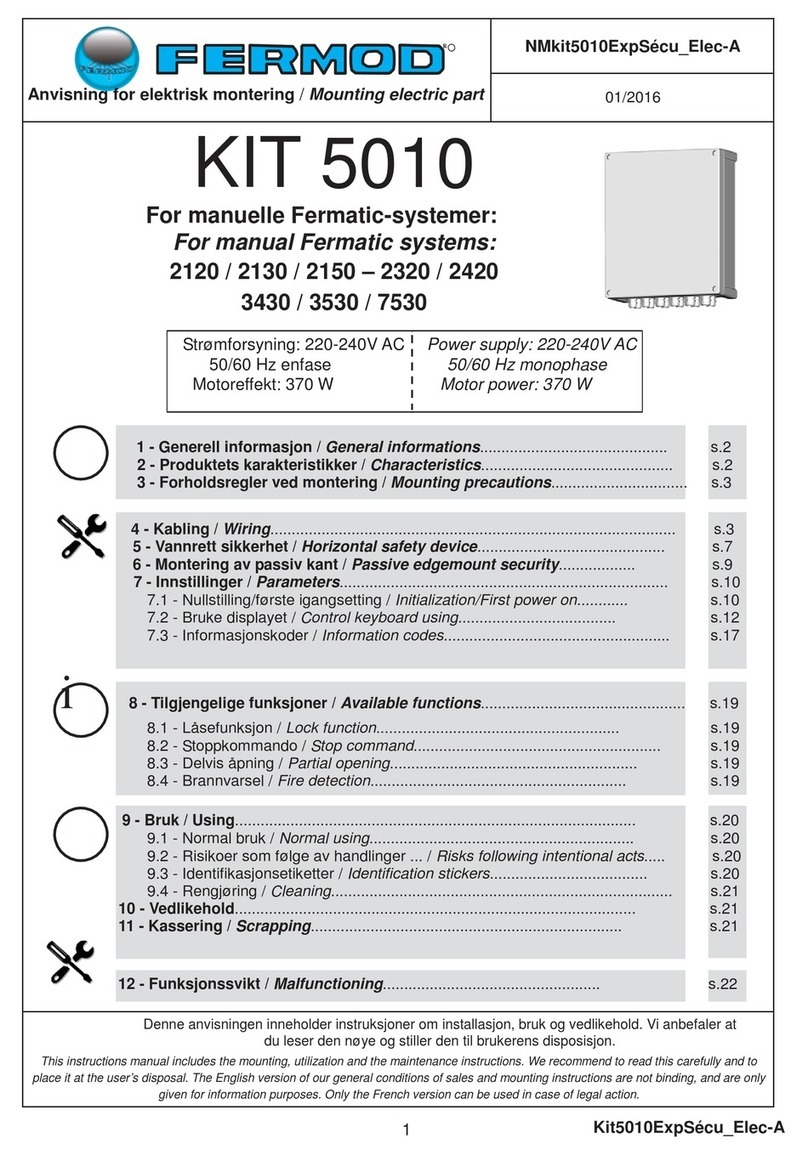
FERMOD KIT 5010 User manual

NMKit5010_RailAlu-C
1
i
i
2120 / 2130 / 2150 2320 / 2420
p.2
p.2
p.2
p.3
p.7
p.9
p.10
p.10
p.12
p.17
p.19
p.19
p.19
p.19
p.20
p.20
p.21
p.21
Cette notice comporte les instructions d'installation, d'utilisation et de maintenance.
Nous vous conseillons de la lire attentivement, et de la mettre à disposition de l'utilisateur.
This instructions manual includes the mounting, utilization and the maintenance instructions. We recommend to read this carefully and to place it at the user’s
disposal. The english version of our general conditions of sales and mounting instructions are not binding, and are only given for information purposes.
Only the french version can be used in case of legal action.
1 - Précautions de montage / Mounting precautions.......................................
2 - Transport.........................................................................................................
3 - Stockage / Storage.........................................................................................
4 - Caractéristiques du produit / Characteristics.............................................
5 - Montage mécanique / Mechanical mounting..............................................
5.1 - Préparation du rail / Rail preparing...........................................................
5.2 - Tendeur de courroie / Belt adjuster..........................................................
5.3 - Entrainement de porte / Door driving assembly.......................................
5.4 - Moteur / Motor.........................................................................................
5.5 - Courroie / Belt.........................................................................................
5.6 - Pose des étiquettes de sécurité / security stickers xing.........................
6 - Utilisation / Using.............................................................................................
6.1 - Utilisation prévue / Normal using..............................................................
6.2 - Risques consécutifs à des actions... / Risks following intentional acts.................
6.3 - Etiquettes d’identication / Identication stickers.....................................
6.4 - Nettoyage / Cleaning................................................................................
7 - Maintenance......................................................................................................
8 - Mise au rebut / Scrapping................................................................................
KIT 5010
04/2017
R
Notice de Montage
Mounting Instructions / Montageanleitung
NMkit5010_RailAlu-C
Pour systèmes Fermatic manuels :
For manual Fermatic systems:
Für die manuellen Fermatic-Systeme:
2120 / 2130 / 2150 - 2320 / 2420
Siehe Seite 22

NMKit5010_RailAlu-C
2
2 - TRANSPORT
Ce matériel doit être transporté à l'abri des intempéries.
Le conditionnement d'origine est prévu pour tous les types de transport.
Le kit conditionné, supporte le gerbage de 4 autres kit automatiques.
La responsabilité de FERMOD s'arrête :
- dès que le client ou l'installateur ouvre le carton ou une partie du carton,
- dès que le carton a subi un choc tel que le carton a été arraché.
This equipment must be protected from bad weather during transport.
The original packing is designed for all types of transportation means.
The packed kit withstands stacking of 4 others automatic kits.
The liability of FERMOD ceases:
- as soon as the customer or installer opens the package or a part of the packaging,
- as soon as the package has suered a considerable impact in such a way that it’s damaged.
3 - STOCKAGE / STORAGE
Ce matériel doit être stocké à l'abri des intempéries.
Le kit conditionné supporte le gerbage de 4 autres kits automatiques.
This equipment must be protected from bad weather during storage.
The packed kit withstands stacking of 4 others automatic kits.
1 - PRECAUTIONS DE MONTAGE / MOUNTING PRECAUTIONS
Veuillez respecter les réglementations en vigueur dans le pays d’installation.
Les points suivants doivent être vériés :
- Vérier les conditions climatiques de l’environnement. Pour les températures inférieures à -10°C, le coret est spécique.
- L’adéquation entre le kit automatique à installer et le système manuel utilisé.
- Les xations du sous ensemble entraînement de porte, doivent être en tout point de bonne fabrication, réalisées dans un
matériau adapté, avoir une résistance appropriée et être exempts de tout défaut évident pendant la durée de vie utile prévue.
Veuillez suivre toutes les instructions de la notice.
Please respect the regulations that apply in the country of installation.
- Check the temperature of the environment. For temperatures lower than –10°C, a low temperature command box is required.
- Check the compatibility between the Automatic Kit to be installed with the Fermatic Manual System.
- The door drive sub-assembly xations must be well made and made of suitable material, having an appropriate resistance
and be exempt from any obvious fault for their intended working life.
Please refer to our mounting instructions.

NMKit5010_RailAlu-C
3
Ces systèmes manuels équipent les portes coulissantes horizontales à caractéristiques spécifiques
(isotherme, acoustique, salle propre ou grise, étanche à la poussière….).
Il possède un verrouillage intégré (qui ne remplace pas l’utilisation d’une serrure) et peut être équipé de
sécurité horizontale ou verticale (en fonction des réglementations en vigueur dans le pays d’installation).
These manual systems are used for horizontal sliding doors with defined characteristics (iso-thermal,
acoustical, clean room, dust-tight…).
It has an integrated lock (which does not replace the use of a mechanical lock), and can be equipped with
horizontal or vertical safety device (according to the regulations that apply in the country of installation).
4 - CARACTERISTIQUES DU PRODUIT / CHARACTERISTICS
Le kit automatique électronique 5010 est destiné à motoriser les systèmes Fermatic suivant :
The automatic electronic kit 5010 is designed to motorize the Fermatic manual systems:
Options spéciques / Options
Les équipements suivant sont disponibles pour les systèmes Fermatic équipés du Kit 5010 :
Sécurité horizontale ou verticale (en fonction des réglementations en vigueur dans le pays d’installation)
Feu clignotant
Nous consulter pour toute demande spécique (bordure résistive, tirette...).
Poignées :
Toutes les poignées prévues pour les systèmes Fermatic manuels s’adaptent sur les systèmes
équipés du Kit 5010.
Options:
Horizontal or vertical safety device (according to the regulations that apply in the country of installation)
Flashing light
Please contact us for other options (resistive edgemount, pull cord...).
Handles :
Every handle for Fermatic manual systems t on systems equiped with kit 5010.
2120 2130
2320
2150
2420
Poids de porte maxi
Maxi door weight 60 Kg 80 Kg 120 Kg
Puissance moteur
Motor power 370W
Classe d'étanchéité du moteur
Protection of the motor IP 55
Température d'utilisation
Using temperature -30°C +45°C *
Fermatic 2320
Fermatic 2120 Fermatic 2130 Fermatic 2150
Fermatic 2420
*Pour les températures négatives :
voir l’option Basse Température - notice séparée
*For negative temperature:
see «option for minus temperature» - Separate mounting instructions
Systèmes Fermatic 3430 / 3530 / 7530 : voir notice séparée NMKit5010_RailAcier
Fermatic systems 3430 / 3530 / 7530: see separate mounting instructions NMKit5010_RailAcier
i

NMKit5010_RailAlu-C
4
M1 Tendeur de courroie
Belt adjuster
M2 Visserie tendeur / Adjuster screws
2120/30/50 - 2320 - 2420
M4 Entraînement de porte
Door driving assembly
M6 Ensemble moteur
Motor unit M3 NE PAS UTILISER
DO NOT USE
M7 Visserie moteur / Motor screws
2120/30/50 - 2320 - 2420 M5 NE PAS UTILISER
DO NOT USE
M9 Courroie / Belt M8 NE PAS UTILISER
DO NOT USE
Nomenclature / Parts list
M1
M2
M3
M4
M5
M7
M8
M9
M6

NMKit5010_RailAlu-C
5
179
A
B
200
600
X
Encombrement / Dimensions
R’
R’ + 168
A
B
2120 :
2130/2150 : *
**
200
600
X
R’
R’ + 178
166*
183**
2120
2130 2150 2320 2420
Xmini 900 900 900 900
maxi 2600 2600 2600 2595
A2X + 224 2X + 224 2X + 190 2X + 200
B2X + 613 2X + 593 2X + 560 2X + 565
Fermatic 2320
80 Kg maxi
Fermatic 2120
60 Kg maxi
Fermatic 2130
80 Kg maxi
Fermatic 2150
120 Kg maxi
Fermatic 2420
120 Kg maxi
C
X = largeur de porte
Door width
R’ = recouvrement supérieur
Upper overlapping
(Page suivante)
(See next page)
X = largeur de porte
Door width
R’ = recouvrement supérieur
Upper overlapping
x3 ou/
or 5
x3 ou/or 5 x5 ou/or 7
x3 ou/
or 5 x5 ou/
or 7
(Page suivante)
(See next page)

NMKit5010_RailAlu-C
6
389
365
370
359
389
365
370
359
181
155
160
151
206
176
185
180
10 - 13 4
8 - 10 - 17
Outils / Tools
Montage coté gauche
Left side mounting
Montage coté droit
Right side mounting
Montage 90° coté gauche
90° Left side mounting
Montage 90° coté droit
90° Right side mounting
2120
2130
2150
2320
2420

NMKit5010_RailAlu-C
7
Le montage du kit 5010 est identique quelque soit le sens d’ouverture de la porte.
Il est préconisé de monter le moteur côté droit du rail.
Le moteur peut se monter en position standard ou incliné à 90°.
Installation of the Kit 5010 is the same regardless of the opening side of the door.
It’s recommended to install the motor right side of the rail.
Motor can be mounted in standard or 90° direction.
La position de l’entrainement de porte (M4) est diérente
selon le sens de montage du moteur sur le rail (côté
droit ou gauche : voir page suivante).
The position of the door driving assembly (M4) is dierent
according to the mounting side of the motor onto the rail
(left or right side: see next page).
5 - MONTAGE MÉCANIQUE / MECHANICAL MOUNTING
Sens ouverture
(à droite)
Opening side
(RH)
Sens ouverture
(à gauche)
Opening side
(LH)
MONTAGE DU MOTEUR CÔTÉ DROIT DU RAIL
MOTOR MOUNTING RIGHT SIDE OF THE RAIL
!
!
200
!200
M4
M4
OU / OR
i
M9 Courroie
Belt
p. 17
M6 Moteur
Motor
p. 12/14
M1 Tendeur courroie
Belt adjuster
p. 10
M4 Entrainement porte
Door driving assembly
p. 10

NMKit5010_RailAlu-C
8
600
600
200
200
Si l’installation ne permet pas un montage standard du moteur (côté droit du rail), il est tout à fait possible
de le monter côté gauche, avec un minimum de modications par rapport au montage standard :
Inverser la position du tendeur de courroie (M1) et de sa vis de réglage (A)
Inverser la position de l’entrainement de porte (M4)
Inverser la position du moteur (M6) sur son support
Pour procéder au montage des diérents éléments du kit,
se reporter aux rubriques du montage standard indiquées
ci-dessous en inversant les vues.
Depending on the system installation, the space available in the right
end rail can be short for mounting the motor in its standard con-
guration (right side of the rail). In that event it’s possible to mount
the motor left side of the rail, with very little changes compared with
standard mounting. It’s necessary to:
Reverse the position of the belt adjuster (M1) and its adjustment
screw (A)
Reverse the position of the door driving assembly (M4)
Reverse the position of the motor (M6) on its bracket
To mount the dierent parts of the Kit, see the drawings below.
Remember to reverse the drawings of the standard mounting.
Support central
Central bracket
MONTAGE DU MOTEUR CÔTÉ GAUCHE DU RAIL
MOTOR MOUNTING LEFT SIDE OF THE RAIL
Sens ouverture
(à droite)
Opening side
(RH)
Sens ouverture
(à gauche)
Opening side
(LH)
Support central
Central bracket
M9 Courroie
Belt
p. 17
M4 Entrainement porte
Door driving assembly
p. 11
!
M6 Moteur
Motor
p. 15/16
OK
A
!10
M1 Tendeur courroie
Belt adjuster
p. 10
Montage en usine - En cas de démontage
la garantie ne sera plus assurée
Factory assembly - In case of disassembly
the warranty will no longer be assured
!
NE PAS DEMONTER
LE MOTEUR,
LE REDUCTEUR
ET LE CODEUR
DO NOT DISMOUNT THE MOTOR,
THE REDUCER AND THE ENCODER

NMKit5010_RailAlu-C
9
2
3
1
1
2
3
PREPARATION DU RAIL / RAIL PREPARING
5.1
13 13
6
C CC MT
X3 X6
X6
X8
X5
X7
2320 / 24202120 / 2130 / 2150
2
3
2
pour cache
for cover
=
=
=
C CC MT
C CCC C MT
OU / OR
OU / OR
1 1
C = M = T =
pour moteur
for motor
pour tendeur
for belt adjuster
Remonter l’embout de rail ou la butée et
les vis de support de rail.
Mount the rail end cover or the butt and the
rail holder screws.
4

NMKit5010_RailAlu-C
10
TENDEUR DE COURROIE / BELT ADJUSTER
5.2
600
Support central
Central bracket
13
OK
!
M1
M2
ENTRAINEMENT DE PORTE / DOOR DRIVING ASSEMBLY
5.3
AVEC MOTEUR CÔTÉ DROIT DU RAIL
WITH MOTOR RIGHT SIDE OF THE RAIL
!
M4
Pour un système Fermatic préalablement installé
For a manual Fermatic system already installed
*=
Sangle
Strap
Cales
Wedges
1
2
Support
de porte
Door
bracket
1
2
EXTERIEUR PORTE
DOOR / OUTSIDE
10
20
32,5
32,5
32,5
32,5 210
5 trous pour vis Ø 8
5 holes for screws Ø8
3
1*
2*

NMKit5010_RailAlu-C
11
M4
M4
EXTERIEUR PORTE
DOOR/OUTSIDE
EXTERIEUR PORTE
DOOR/OUTSIDE
Bloquer
Block
Bloquer
Block
3
3
1
1
2
2
AVEC MOTEUR CÔTÉ GAUCHE DU RAIL
WITH MOTOR LEFT SIDE OF THE RAIL
M4
!
Pour un système Fermatic préalablement installé
For a manual Fermatic system already installed
*=
Sangle
Strap
Cales
Wedges
1
2
Support
de porte
Door
bracket
1
2
EXTERIEUR PORTE
DOOR/OUTSIDE
10
20
32,5
32,5
32,5
32,5
210
5 trous pour vis Ø 8
5 holes for screws Ø8
5 vis Ø8
tête fraisée
(non fournies)
5 countersunk
screws Ø 8
(not supplied)
45 vis Ø 8 tête fraisée
(non fournies)
5 countersunk screws
Ø 8 (not supplied)
3
4
5*
1*
2*
5*

NMKit5010_RailAlu-C
12
MOTEUR / MOTOR
5.4
21502120 / 2130
COTÉ DROIT
RIGHT SIDE
COTÉ DROIT
RIGHT SIDE
13 13
A
≈ 150
15
B
206
!
≈ 150
A
206
!
15
B
BA
1
2
M6
1
1
2
OK
!
Bloquer
Block
Bloquer
Block
13
11
2 2
3
4
Montage côté droit du rail 2120/2130/2150
Mounting right side of the rail
BA
1
2
M6
1
1
2
OK
!
13
3
4
Haut/Top
Bas/Bottom
B A
!
B
A
C
M7
!
NE PAS DEMONTER LE MOTEUR,
LE REDUCTEUR ET LE CODEUR
DO NOT DISMOUNT THE MOTOR,
THE REDUCER AND THE ENCODER

NMKit5010_RailAlu-C
13
175
!
15
C
B
13
6
24202320
COTÉ DROIT
RIGHT SIDE
COTÉ DROIT
RIGHT SIDE
170
15
!
1
13
B
6
C
M6
1
2
OK
!
13
3
4
BC
1
M6
1
2
OK
!
13
3
4
BC
1
1
B
C
A
M7
2
Bloquer
Block
Bloquer
Block
2
!
BC
Haut/Top
Bas/Bottom
Montage côté droit du rail 2320 / 2420
Mounting right side of the rail
!
NE PAS DEMONTER LE MOTEUR,
LE REDUCTEUR ET LE CODEUR
DO NOT DISMOUNT THE MOTOR,
THE REDUCER AND THE ENCODER

NMKit5010_RailAlu-C
14
Montage du moteur à 90° côté droit / 90° right side motor mounting
10 10
10 10
M6
90° 10
10
10
10
1 2
43 !
!
ou/or
5
En fonction de l’installation, la place disponible en bout de rail
côté droit peut être insusante pour monter le moteur dans sa
conguration standard. Dans ce cas il est possible de monter
celui-ci en l’inclinant à 90°, de façon à réduire son encombrement.
Depending on the system installation, the space available in the
right end rail can be short for mounting the motor in its standard
conguration. In that event it’s possible to mount the motor in 90°
direction.
!
NE PAS DEMONTER LE MOTEUR,
LE REDUCTEUR ET LE CODEUR
DO NOT DISMOUNT THE MOTOR,
THE REDUCER AND THE ENCODER
Ne pas demonter
le moteur, le réducteur
et le codeur
Do not dismount
the motor, the reducer
and the encoder
!

NMKit5010_RailAlu-C
15
!
M6
M6
180°
180°
!
3 4
10
10
10
10
10 10
10 10
2
ou/or
1
ou/or
5 6
Transformation du moteur pour
montage côté gauche
Transformation of the motor for left side mounting
!
NE PAS DEMONTER LE MOTEUR,
LE REDUCTEUR ET LE CODEUR
DO NOT DISMOUNT THE MOTOR,
THE REDUCER AND THE ENCODER
Ne pas demonter
le moteur, le réducteur
et le codeur
Do not dismount
the motor, the reducer
and the encoder
!

NMKit5010_RailAlu-C
16
M6
90°
180°
!
10 10
Faire pivoter le support à 180°.
!
!
10
10
10
10
2
3
5
1
4
6
ou/or
ou/or
Montage du moteur à 90° côté gauche
90° left side motor mounting
!
NE PAS DEMONTER LE MOTEUR,
LE REDUCTEUR ET LE CODEUR
DO NOT DISMOUNT THE MOTOR,
THE REDUCER AND THE ENCODER
Ne pas demonter
le moteur, le réducteur
et le codeur
Do not dismount
the motor, the reducer
and the encoder
!

NMKit5010_RailAlu-C
17
STOP
COURROIE / BELT
5.5
Liaison courroie / porte - Link belt/door
8
Bloquer
Block
10
10
STOP
8 !
10
10
2
3
6
2
4
3
1
2
1
1
2
1OK
PORTE FERMÉE / DOOR CLOSED
!
M4
M9
M9
M4
4
Resserrer à la main
Manually tighten
ou/or
ou/or
5

NMKit5010_RailAlu-C
18
Tension courroie / Tighten the belt
13
12
2
113
Bloquer
Block
17
Encoche
Notch
43 M1
Serrer
Tighten
10
Horizontal
17
6 7
2
1/2 tour
1/2 round
5
Bloquer
Block

NMKit5010_RailAlu-C
19
Les étiquettes doivent être placées le plus près possible des zones de risque.
Stickers must be as nearest as possible to the risk.
6 - UTILISATION / USING
Respecter les spécications du § 4 - Caractéristiques du produit. Utiliser les commandes prévues (bouton, badge...).
En cas de panne des portes motorisées :
L'utilisateur peut ouvrir la porte en actionnant la poignée intérieure ou extérieure.
Précautions :
En cas d’urgence : Appuyer sur le bouton noir du boîtier de commande (arrêt du moteur).
En cas de panne : Couper le sectionneur et utiliser les poignées prévues à cet eet.
.Ecrasement des doigts placés entre la
courroie et les poulies (tendeur ou moteur)
.Ecrasement des doigts placés entre
l'entraînement de porte et le dessous du rail
.Main placée entre le chariot et la butée,
en n d'ouverture ou de fermeture
.Main placée sur la bande de roulement,
lors du déplacement du vantail (galets)
.Risque d’électrocution
. Ne pas projeter d'eau
. Ne pas projeter de poussières ou de copeaux
. Ne rien introduire dans le coret
électrique
6.1 UTILISATION PREVUE / NORMAL USING
6.2 Risques consécutifs à des actions intentionnelles de personnes autres que l’utilisateur
Risks following intentional acts of persons other than the user
i
POSE DES ETIQUETTES DE SECURITE / SECURITY STICKERS FIXING
5.6
Respect § 4 specications - Product Characteristics. Use the required commands (wall button, badge ...).
In case of failure:
The user can open the door with the internal or external handle.
Safety measures:
In case of emergency: push on the black button of the wall command box ( stop the motor).
In case of failure: put the switch o and use the required handle.
.Crushing of ngers placed between the belt
and the pulleys (belt adjuster and motor)
.Crushing of ngers placed between the door
drive and the above of the rail
.Handle between trolley and butt during the
end of door opening or closing
.Handle on the way of the rollers, when the
door moves
. Danger: risk of electric shock
. Do not spray with water
. Do not spray dust or shavings
. Do not introduce anything into
command box

NMKit5010_RailAlu-C
20
6.3 ETIQUETTES D’IDENTIFICATION / IDENTIFICATION STICKERS
Classe d'étanchéité du moteur : IP55 - Ne pas arroser à grand jet le moto-réducteur
Classe d’étanchéité du coret : IP65
Protection contre les fortes projections par le cache adapté.
Le nettoyage de la porte doit exclure l’utilisation d’un jet d’eau sous haute pression sur les appareillages électriques :
sectionneur, boutons poussoir, unité de commande, moto réducteur, sécurité optique verticale, sécurité
optique horizontale.
Le nettoyage des matériels doit être réalisé avec des produits lessiviels compatibles avec les matériaux du produit fourni.
Pour les pourcentages de dilution, se référer aux notices des produits lessiviels utilisés.
Matériaux : - Entraînement de porte / Tendeur courroie : acier zingué
- Support moteur : aluminium
6.4 NETTOYAGE / CLEANING
Water tightness class of the motor: IP55 - Do not splash.
Water tightness class of the command box: IP65
Protection against water splashes with the suited cover.
Cleaning the door must exclude the use of a water jet on electrical appliances: push buttons, control unit, reduction gear,
horizontal optical safety.
The equipment should be cleaned using cleaning agents that are compatible with the materials of the supplied product.
For the dilution percentages, refer to the instructions of the cleaning agents to be used.
Materials: - Door driving assembly / Belt adjuster: zinc steel
- Motor bracket: aluminium
Plaque moteur
Motor identication
SPECIMEN
Etiquettes non contractuelles susceptibles d'évoluer
Stickers data only for information - Subject to modications
SPECIMEN
Support moteur
Motor bracket
SPECIMEN
Entrainement de porte
Door driving assembly
SPECIMEN
Tendeur de courroie
Belt adjuster
Modèle d’étiquette de marquage CE
(pour Kit 5010 version CE seulement)
EC sticker example
(only for kit 5010 CE)
SPECIMEN
Condition de garantie
Warranty conditions
i
Other manuals for KIT 5010
3
This manual suits for next models
1
Table of contents
Other FERMOD Door Opening System manuals
Popular Door Opening System manuals by other brands
Cavity Sliders
Cavity Sliders Solic CS005 Operation manual
RollSeal
RollSeal RS-600 Series manual
Aprimatic
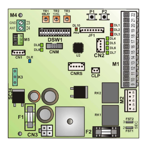
Aprimatic SC 24 Use and maintenance instructions

Open Sesame Door Systems
Open Sesame Door Systems 133 owner's manual
Remote Solutions
Remote Solutions SR-U SDB-60A5-0216 Operation manual
Automatic Technology
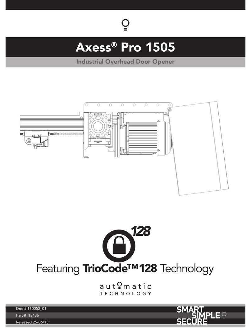
Automatic Technology Axess Pro 1505 installation instructions
