Ferret 44 User manual

1
www.gxtauto.com
OPERATOR’S MANUAL
Battery Electrical And Starting Tester
© Copyright 2005, GxT, Inc., All Rights Reserved
© Copyright 2005, GxT, Inc., All Rights Reserved

2
www.gxtauto.com
Test & Measurement Specifications
RPM
....................................................................................................................................................
0-10,000 RPM
RPM Type
.........................................................................................................
Inductive, Plug in Field Replaceable
Battery Volts
...................................................................................................................................
4.0 to 19.99 Volts
External Volts (10 Megohm Impedance)
.....................................................................................
0 to +/- 39.90 Volts
Inductive Amps
........................................................................................................................................
0 to +/- 600
Amps Type
........................................................................................................
Inductive, Plug in Field Replaceable
Load Range
........................................................................................................................................
0 to 600 Amps
Load Type
................................................................................................................................................
Carbon Pile
Load Configuration
.................................................................
Clockwise = On, Counterclockwise = Spring Loaded
Battery Condition
.........................................................................................
Estimated Cold Cranking Amps Rating
Amps Ripple
........................................................................................................................................
LCD Indicator
Load On Indicator
................................................................................................................................
LCD Indicator
Load Hot Indicator
..............................................................................................................................
LCD Indicator
Display Information
Display Type
.................................................................................................................................
2 Line Backlit LCD
Bargraph
.................................................................................................................................................
31 Segment
Refresh Rate
....................................................................................................................
3 times a second or better
Printer
........................................................................................................................................
Thermal, 40 Column
Physical Dimensions
Case Size
......................................................................................................................................
10 x 16.5 x 9.5 in.
Weight
......................................................................................................................................................
45 Pounds
Power Requirements
..........................................................................................................................
12 Volt Battery
Replacement Parts
Axle Cap
.......................................................................................................................................................
B000-07
Axle
...............................................................................................................................................................
G001-26
Wheel, 8”
......................................................................................................................................................
H000-07
Thermal Printer Paper, 80mm or 3 1/8”
........................................................................................................
H013-02
Extension Lead for 5 Pin Din
.......................................................................................................................
W000-03
Spark Pickup
................................................................................................................................................
X008-01
High Amps Probe
.........................................................................................................................................
X000-02
Introduction
Equipped with a thermal printer, advanced computer aided system tests and a large display. This tester has the
ability to the estimate cold cranking amps of the battery and detect batteries likely to fail in the near future. Large
simple controls and labeling. Inductive Amp probe makes hookup easy. Welded steel with baked powder coat
finish. Carbon pile loads output. Inductive amp probe measures output and indicates defective diode/stators.
Checks voltage regulation. Applies up to 600 amp test current and measures voltage. Timer sounds after 15
seconds of load. Checks current draw and cable/solenoid resistance voltage drops.
1” x 3/4” opening clamps
around large battery cables and wire bundles. Plug-in user replaceable probe.
Control knob sets load current to
a stable test amperage. Fan cooled for heavy duty service. Easily tests 1200 CCA Batteries. Side handle cable
exits make hookups easier and more secure. Cables are jacketed to reduce tangles.
Technical Support
Questions or inquiries about service can be answered by contacting GxT, Inc., at:
When sending an item to the factory address it to:
GxT, Inc., 520 MM Riggs Drive., Cheboygan, MI 49721-1061
Include a note describing the problem.

3
www.gxtauto.com
Table of Contents
Test & Measurement Specifications
.........................................................................................................................
2
Display Information
..................................................................................................................................................
2
Physical Dimensions
................................................................................................................................................
2
Replacement Parts
...................................................................................................................................................
2
Introduction
..............................................................................................................................................................
2
Technical Support
.....................................................................................................................................................
2
Warranty
...................................................................................................................................................................
3
Keypad
.....................................................................................................................................................................
4
Indicators & Messages
.............................................................................................................................................
4
Installing Printer Paper
.............................................................................................................................................
5
Stand Assembly
.......................................................................................................................................................
5
Battery Test (Manual)
................................................................................................................................................
6
Battery Test (Automatic)
...........................................................................................................................................
7
Starter Test (Manual)
................................................................................................................................................
8
Voltage Drop Test
.....................................................................................................................................................
8
Starter Test (Automatic)
............................................................................................................................................
9
Alternator Output Test (Manual)
.............................................................................................................................
10
Regulator Charging Voltage Test
............................................................................................................................
10
Alternator Output Test (Automatic)
.........................................................................................................................
11
Safety Precautions
.................................................................................................................................................
12
Warranty
FERRET BRAND LIMITED PRODUCT WARRANTY
GxT, Inc. of Cheboygan Michigan, warrants to the original purchaser that FERRET brand prod-
ucts are free from defects in materials and workmanship for a period of two years from date of
purchase. Our sole obligation for a product within the above warranties will be to repair or re-
place, at our option, any defective parts and return the product to the sender within the U.S.A.,
shipping prepaid, if it is sent to our Repair Department shipping prepaid and accompanied by
proof of purchase.
This Warranty does not apply to products which have been altered outside the factory; or repaired
by anyone other than the factory or its authorized service centers; or which have been damaged
from accidents, negligence, or abuse; or have been used differently than described in the printed
instructions. Please note that wear and tear on leads and replacement of consumable items such
as: NOx Sensors, Oxygen Sensors, and paper, is not covered by warranty.
GxT Inc.’s sole liability and buyer’s exclusive remedy is limited to repair or replacement of the
product as stated in the Limited Product Warranty. THERE ARE NO OTHER WARRANTIES
EXPRESSED OR IMPLIED INCLUDING THOSE OF MERCHANTABILITY OR FITNESS FOR
A PARTICULAR PURPOSE AND GxT, INC. SHALL NOT BE LIABLE FOR INCIDENTAL OR
CONSEQUENTIAL DAMAGES ARISING FROM THE SALE OR USE OF THE PRODUCT.
Some states do not allow limitations on the length of implied warranties nor exclusion or limita-
tions of incidental or consequential damages, so that the above limitations
and/or exclusion may
not apply to you.
This warranty gives you specific legal rights and you may also have other rights which may vary
from state to state.

4
www.gxtauto.com
Keypad
Amps/Ext V
Pressing the Amps/Ext V button will display amperage measurements from the High Amps Probe on the upper
display, and the voltage measurements from the external volts leads on the bottom display.
Amps/Batt
Pressing the Amps/Batt button will display amperage measurements from the High Amps Probe on the upper
display, and the voltage as measured from the Battery Clamps. This test configuration is the most widely accepted
measurement configuration for typical Battery Testers.
RPM/Amps
Pressing the RPM/Amps button will display the RPM of the engine on the upper display, and the amperage
measurements from the High Amps Probe on the lower display.
RPM/Batt
Pressing the RPM/Amps button will display the RPM of the engine on the upper display, and the battery voltage
on the lower display.
RPM/Ext V
Pressing the RPM/Ext V button will display the RPM of the engine on the upper display, and the voltage measurements
from the external volts leads on the bottom display.
Amps Zero
Pressing this button will zero the amp probe.
Print
Press this button to print whatever is on the display.
2C/4C
Press this button to configure the RPM measurement to be compatible with 2 cycle or 4 cycle engines.
Batt
Pressing this button will activate an automatic test of the battery. See the test details further in the manual.
Start
Pressing this button will activate an automatic test of the Starting System. See the test details further in the
manual.
Charge
Pressing this button will activate an automatic test of the Charging System. See the test details further in the
manual.
Special Key Combinations
Press the Print and 2C/4C buttons at the same time to advance the paper.
Indicators & Messages
LOad HOT
When this message is displayed on the LCD, the carbon pile is getting too hot. Immediately turn off the load and
let the fan cool the carbon pile. Then the LOad HOT message is not display, you can continue testing.
“Diode Symbol”
If the Diode symbol on the LCD is on, your alternator has an open or shorted diode or stator. This indicator is most
accurate when the battery is under a load and the RPM is above 1,000 RPM.
5
www.gxtauto.com
!!
!
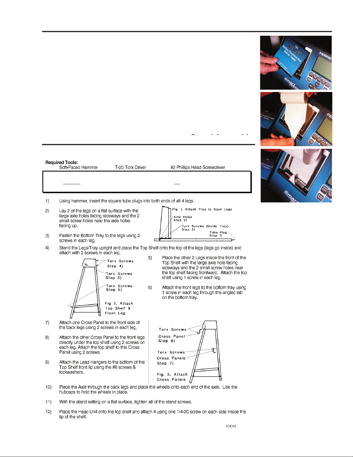
Installing Printer Paper
The battery tester has a built in 40 column thermal dot matrix printer that uses paper
that is 80mm or 3.18” wide.
To Install the paper, remove the printer cover.
The easiest pay to load the paper is to cut the paper into an arrowhead. Feel the
paper into the printer as shown in the pictures. Once you see the point of the
arrowhead appear, grab the tip of the paper and gently pull the paper until the full
width of the paper has been fed through the printer. Tear off the paper.
Install the paper into the paper holder by holding down on one or both of the pins
found at the top of the printer housing.
Reinstall the printer cover. You are now ready to print.
Stand Assembly
Stand Assembly
6
www.gxtauto.com
Battery Test (Manual)
CAUTION
Wear Safety Glasses, Do not break live circuits at the battery
terminals, Avoid accidentally shorting the insulated battery
terminal to any ground metal. Never put a wrench on a live
battery wire terminal. Burns may be the result. Disconnect
the battery chassis cable first.
1. Be sure the Load Knob is turned to OFF before connecting
the analyzer cables to the battery. Take note of the safety
precautions on the back cover of this manual.
2. Connect the analyzer Battery Clamps to the battery
terminals; Red to positive, Black to negative. The
cable jaw contact from each clamp must make a solid
connection to the battery terminal to assure good voltage
measurements and avoid sparks during load tests. Side
terminal batteries may need special adapters attached to make solid connections for high current load tests.
3. Press the Amps/Volts Test Button.
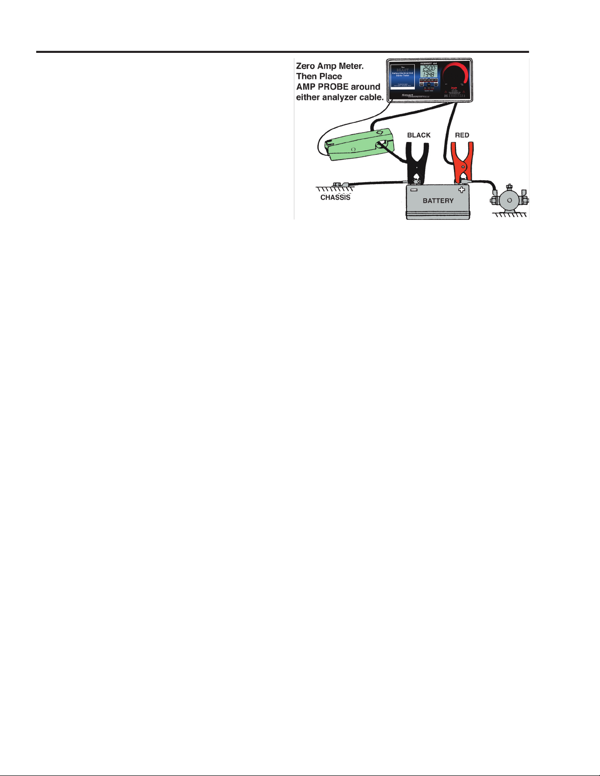
4. With the Amp Probe jaws closed and not around any wires, press the Zero Amps button until the Amps Display
shows “000”
5. Connect the Amp Probe around either analyzer load lead.
Open Circuit Voltage Test
Measure the open circuit (no load) stabilized voltage. A stabilized battery has no “surface charge”, which means
that the electrolyte has had a chance to remix and shed gas bubbles after current flow has stopped. With less than
12.4 volts, first recharge the battery.
Open Ckt. Volts 12.6 12.4 12.2 12.0
% of Charge 100 75 50 25
Load Test
1. Determine the battery load test amperes from the battery test specification, CCA, or Ah ratings. To give consistent
results a load test requires that a battery be at least 75% charged and not have been heavily used within the
last 10 minutes.
Cold Cranking Amperes at 0°F. (CCA)
Use 1/2 the CCA for a load test. For example, 360 CCA divided by 2 equals a 180 ampere
test load.
Ampere Hour Rating (Ah)
Multiply the Amp Hour Rating by 3 to obtain the load. For example, a 60 Ah battery times
3 equals a 180 ampere load.
2. Turn the Load Control Knob clockwise until the amps reading gradually reaches the required load. Watch the
battery voltage. After 15 seconds at the test amperage, or if the voltage goes below the minimum value, turn
the load off. NOTE: The Load-on Lamp flashes and beeps once per second. After 16 seconds of load current,
the beeper will sound continuously.
LOAD TEST CAUTION
If a battery smokes while being loaded, stop testing immediately. It is not safe.
3. Test Conclusions. If the battery voltage went below the minimum voltage from the table during the test the battery
is either discharged or defective. Recharge and test again if necessary.
At 70°F and higher a good battery will maintain an output of 9.6 volts or more during the loading period (4.8 volts
for 6 volt batteries). When a battery is cooler than 70°F, the output voltage requirement is reduced to give equivalent
test conclusions per the following table:
ELECTROLYTE TEMP. MINIMUM
——°F—— ——°C—— LOADED VOLTS
70 21 9.6
60 16 9.5
50 10 9.4
40 4 9.3
30 – 1 9.1
20 – 7 8.9
10 –12 8.7
0 –18 8.5

7
www.gxtauto.com
Battery Test (Automatic)
CAUTION
Wear Safety Glasses, Do not break live circuits at the battery
terminals, Avoid accidentally shorting the insulated battery
terminal to any ground metal. Never put a wrench on a live
battery wire terminal. Burns may be the result. Disconnect
the battery chassis cable first.
1. Be sure the Load Knob is turned to OFF.
2. Connect the analyzer Battery Clamps to the battery
terminals; Red to positive, Black to negative.
3. With the Amp Probe jaws closed and not around any
wires, press the Zero Amps buttons until the Amps
Display shows “000”
4. Connect the Amp Probe around either analyzer load
lead.
5. Press the BATT button. The analyzer will measure the Open circuit voltage of the battery. When the analyzer
displays “LOAd” you should apply a load equal to 1/2 the Cold Cranking Amps rating.
6. Turn the Load Control Knob clockwise until the amps reading gradually reaches the required load.
7. When the Analyzer beeps, turn off the load. The analyzer will now measure battery recovery time and calculate
the Cold Cranking Amps rating of the battery.
8. At the conclusion of the test, a report will be printed.
* * * * * * * BATTERY TEST * * * * * * *
Open Circuit Voltage 12.76 Volts
Load On Time 15 Seconds
Battery Loaded Voltage 10.87 Volts
Final Load Current 346 Amps
Recovery Time 4 Seconds
BATTERY TEMP. CCA:
Over 15C/60F 697
O-15C/30-60F 730
-15-0C/0-30F 795
Battery Data ____________________________
Tech Name _____________________________
Date ___________________________________
Open Circuit Voltage Test
The open circuit (no load) stabilized voltage of the Battery.
An open circuit voltage of less than 12.4 volts indicates
the battery should be charged before testing.
Load On Time
The time, in seconds, that a load is being applied to a
battery.
Recovery Time
The time it takes the battery to recover from the loaded
voltage to 12.3 volts once the load is removed. Used to
calculate the CCA of the battery. If it takes more than
30 seconds to recover, the battery is weak.
CCA Estimate
The estimated Cold Cranking Amp rating of the
battery. Three readings are given based on the battery
temperature.
Battery & Technicians Information
Use this part of the report to write down the battery
information, your name and the date the test was run.
8
www.gxtauto.com
Starter Test (Manual)
When testing the starting system, first test for battery
performance. With a known good battery, the starter mo-
tor, cables and starter solenoid can be checked. Starter
amps should not exceed the maximum specified for the
vehicle being tested, and the cranking RPM should be
satisfactory.
1. Engine should be at normal operating temperature.
Make sure all lights and accessories are off and vehicle
doors are closed.
2. Be sure the Load Knob is turned to OFF before
connecting the analyzer cables to the battery. Take
note of the safety precautions on the back cover of
this manual.
3. Connect the analyzer Battery Clamps to the battery terminals; Red to positive, Black to negative.
4. With the Amp Probe jaws closed and not around any wires, press the Zero Amps button until the Amps Display
shows “000”
5. Press the Amps/Volts button.
6. Place the Amp Probe around either of the engines battery cables.
7. Set the Volts Selector to Battery Volts.
8. Disable the ignition or fuel system.
9. Crank engine for 15 seconds with ignition key and note the cranking amperage reading. Also, watch to see that the
battery voltage stays above 9.6 V. Wait a few minutes for the starter to cool if the cranking test is repeated
TYPICAL STARTER CRANKING DRAW Engine Size
Cubic Inches Liters Amps Draw
100 to 200 1.6 to 3.2 100 to 200
200 to 350 3.2 to 5.6 125 to 250
350 to 500 5.6 to 8.0 150 to 300
NOTE: Higher starter amps may be encountered if engine temperatures are extremely hot or cold.
9. Test Conclusions. The system is good if the cranking speed is satisfactory and the battery voltage stayed above
9.6 volts. If Crank Speed was slow use the following chart.
Voltage Amps Likely Cause
Below 9.6 High Bad Starter or a very hot or cold engine.
Below 9.6 Low Bad Battery or Loose Battery Terminals.
Above 9.6 Low Connections at Starter or Solenoid.
Voltage Drop Test
The voltage drop test is a very helpful diagnostic test for determining the condition of cables and connections for
the starting charging circuit. The voltage drop test can be used on any part of the circuit. In the example below,
we are checking the entire circuit from the positive side of the battery to the starter.
1. Be sure the Load Knob is turned to OFF before connecting the analyzer cables to the battery. Take note of the
safety precautions on the back cover of this manual.
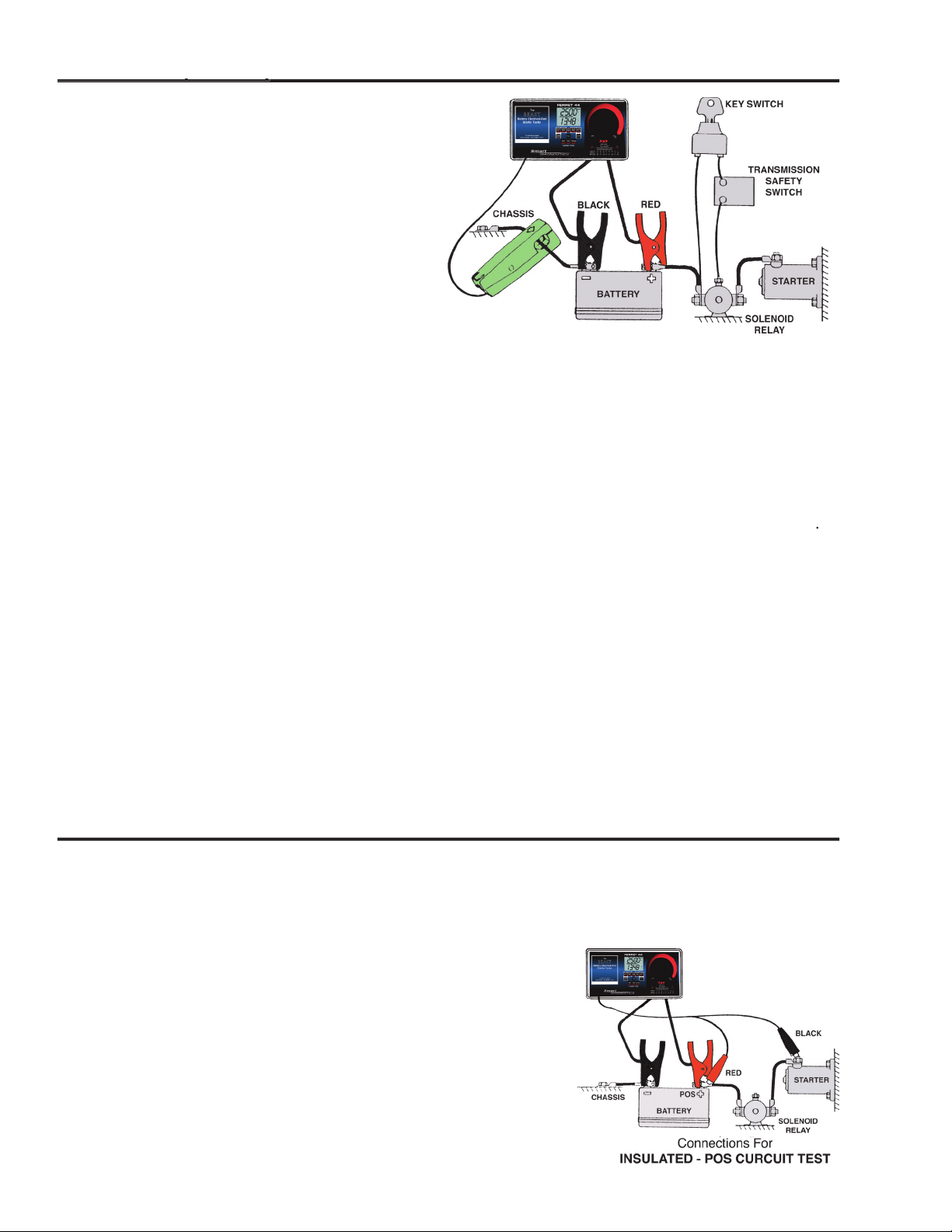
2. Connect the analyzer Battery Clamps to the battery terminals; Red to
positive, Black to negative.
3. Select external volts.
4. Connect the external volts leads as shown in the illustration. Connect the
Red auxiliary lead to the positive side of the battery. Connect the Black
lead to the input terminal of the starter.
5. Disable ignition to prevent the engine from starting during the test.
4. Operate the Starter and read the voltmeter while cranking.
5. Test Conclusions. Good circuits drop less than 0.50 volts on a 12 volt
system. Typically you should not have more than 0.10 volts drop per
connection.
Starter Test (Manual)

9
www.gxtauto.com
Starter Test (Automatic)
When testing the starting system, first test for battery
performance. With a known good battery, the starter mo-
tor, cables and starter solenoid can be checked. Starter
amps should not exceed the maximum specified for the
vehicle being tested, and the cranking RPM should be
satisfactory.
1. Be sure the Load Knob is turned to OFF.
2. Connect the analyzer Battery Clamps to the battery
terminals; Red to positive, Black to negative.
3. With the Amp Probe jaws closed and not around any
wires, press the Zero Amps button until the Amps
Display shows “000”
4. Connect the Amp Probe around either battery cable.
5. Connect the Red spark pickup around any spark plug wire. For ignition systems without spark plug wires, consult
the operators manual.
6. Press the START button.
7. Disable the fuel or ignition system on the vehicle and crank the engine.
8. The bargraph will move indicating the measurements are being taken. When the bargraph will begin moving
indicating the test is underway. When the HOLD indicator comes on the test is finished. Stop cranking.
9. At the conclusion of the test, a report will be printed.
* * * * * * * STARTING TEST * * * * * * *
Cranking Speed 275 RPM
Cranking Duration 15 Seconds
Battery Voltage 10.75 Volts
Starter Draw 90 Amps
Battery Data ____________________________
Tech Name _____________________________
Date ___________________________________
Cranking Speed
The RPM of the engine while the starter is engaged
trying to start the vehicle. Please note if you disable
the ignition system, the RPM will be zero.
Cranking Duration
This is the length of time, in seconds, the starter was
engaged for the test.
Battery Voltage
This is the battery voltage while the starter was en-
gaged.
Starter Draw
This is the amperage draw of the starter.
Battery & Technicians Information
Use this part of the report to write down the battery
information, your name and the date the test was
run.
10
www.gxtauto.com
Alternator Output Test (Manual)
Always compare test results with manufacturer’s specifications before coming to conclusions regarding the
performance or efficiency of charging systems and their components.
1. Be sure the Load Knob is turned to OFF before
connecting the analyzer cables to the battery. Take
note of the safety precautions on the back cover of
this manual.
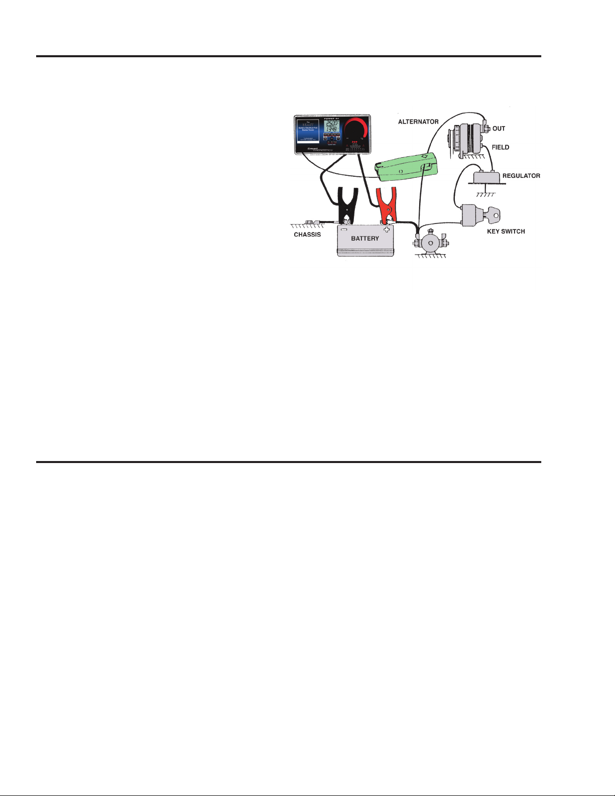
2. Connect the analyzer Battery Clamps to the battery
terminals; Red to positive, Black to negative.
3. With the Amp Probe jaws closed and not around any
wires, press the Zero Amps buttons until the Amps
Display shows “000”
4. Place the Amp Probe around the alternator output
wire. Try to position the probe away from strong
magnetism near the back shaft end of the alternator
to avoid measurement error.
5. Press the Amps/Volts button
6. Start and run the engine at about 2000 RPM.
7. Turn the Load ON and increase until the battery voltage
decreases to be between 12 and 13 volts while reading the output amperage.
8. Turn Load OFF and reduce RPM.
9. Test Conclusions
If the Amps Ripple lamp stayed on during the output test replace the alternator.
If the amperage abruptly decreased during the test check for a loose belt.
If output was less than 90% of rating use the voltage drop test to check output resistance.
If output did not change, full field the alternator. If the alternator output increases, replace the regulator.
Regulator Charging Voltage Test
Follow the same setup and test procedure used for the alternator test, except put the Amp Probe around either
battery cable. Once the charging amperage drops below 20 amps, the voltage displayed will be the regulator
setting. This should be between 13.5 and 15.5 volts on a 12 volt system.

11
www.gxtauto.com
* * * * * * * CHARGING TEST * * * * * * *
Engine Speed 1500 RPM
Battery Voltage 12.45 Volts
Alternator Output 90 Amps
Alternator Ripple OK
Battery Data ____________________________
Tech Name _____________________________
Date ___________________________________
Alternator Output Test (Automatic)
Always compare test results with manufacturer’s specifications before coming to conclusions regarding the
performance or efficiency of charging systems and their components.
1. Be sure the Load Knob is turned to OFF.
2. Connect the analyzer Battery Clamps to the battery
terminals; Red to positive, Black to negative.
3. With the Amp Probe jaws closed and not around any
wires, press the Zero Amps buttons until the Amps
Display shows “000”
4. Place the Amp Probe around the alternator output
wire or positive battery cable. Try to position the probe
away from the back end of the alternator to avoid
measurement error.
5. Connect the Red spark pickup around any spark plug
wire. For ignition systems without spark plug wires,
consult the operators manual.
6. Start and Run the Engine.
7. Press the CHARGE button.
8. Run the engine at about 1500 RPM, and apply a load until the battery voltage decreases to 12.5 volts. The
bargraph will move indicating the measurements are being taken. The HOLD indicator will come on signaling
the end of the test.
9. At the conclusion of the test, turn the load off and let the engine idle. A report will be printed.
Engine Speed
The RPM of the engine.
Battery Voltage
This is the battery voltage during the test.
Alternator Output
This is the amperage output of the Alternator.
Alternator Ripple
If their is excessive alternator ripple, the printout will
show that the amps ripple is high, otherwise, it will
print O.K.
Battery & Technicians Information
Use this part of the report to write down the battery
information, your name and the date the test was
run.

12
www.gxtauto.com
• Always wear eye protection when testing vehicles. Be extra careful near batteries
and moving parts. Do not lay tools on a battery.
• Battery gas is highly explosive.
a. If a battery explodes flush the acid away from persons skin with generous
amounts of water. Follow up with a neutralizing solution of baking soda and
then more water.
Treat clothing, vehicle parts, and equipment similarly. Any acid traces inside
equipment must be removed by generous rinsing. Dry equipment and place
in a warm 50°C (120°F) oven until thoroughly dry.
b. Never use a wrench on the ungrounded battery terminal until the grounded
one has been disconnected. Contact between the vehicle body metal and
the hot terminal can cause sparks to ignite gas or even weld tools into a
battery short circuit.
c. Keep the space around a battery well ventilated.
d. Do not make sparks or allow flames near batteries.
• Before working on a vehicle set the brakes and block the wheels. Beware of
automatic parking brake releases.
• Keep your work area well ventilated and free of exhaust. Engine exhaust contains
deadly poisons. Treat Gas Detector exhaust and drain hoses the same as the
vehicle tailpipe. Both give off deadly exhaust fumes.
• Avoid electrical shocks caused by getting close to live ignition wires or touching
the coil TACH terminal. A person’s reaction near a live engine can be more
damaging than the shock.
• Keep spark producing devices at least 0.5m (18”) above the floor to reduce the
hazard of igniting gasoline vapor.
• Do not let test leads wind up in a moving fan or pulley. Route leads away.
• Remove finger rings and metal wrist bands. They can short terminals and
become very hot from electric current.
SAFETY PRECAUTIONS
E044-01G
Table of contents
Popular Test Equipment manuals by other brands


Solar
Solar BA227 user manual

IDEAL Networks
IDEAL Networks VDV II PRO user guide

Alcolizer
Alcolizer HH4 user manual

Agilent Technologies
Agilent Technologies InfiniiVision 5000 Series Programmer's guide

Megger
Megger PAT300 Series quick start guide

Thermo Scientific
Thermo Scientific Elite PCTS operating instructions


