EN
Temperature unit of measure selection
Follow the instructions given below to use the Remote Control in °C or in °F.
1. Keep the button
pressed for 3 seconds. 2. The display shows the CU parameter.
3. Press the button
7 times. 4. The display shows parameter P6.
Set to 0 using the buttons
to select °C.
Set to 1 using the buttons
to select °F.
5. Press any other button to exit the menu.
Room temperature reading correction
Follow the instructions given below to correct the room temperature reading between -2°C and +2°C in 0.1°C steps.
1. Keep the button pressed for 3 seconds. 2. The display shows the CU parameter.
3. Press the button 8 times. 4. The display shows parameter P7.
Use the buttons to adjust the parameter in 0.1°C increments.
5. Press any other button to exit the menu.
Telephone contact input
Normal
Remote Control
operation is ensured as long as the telephone contact remains open. The closing of this
contact, indicated on the display with the symbols (), can be used to force the
Remote Control
to switch off heating
or to set the room temperature to a preset fixed value.
Follow the instructions given below to set the two functions.
1. Keep the button pressed for 3 seconds. 2. The display shows the CU parameter.
3. Press the button 9 times. 4. The display shows parameter P8.
Set to 0 using the buttons to switch off heating when the contact is closed.
Set to 1 using buttons to adjust room temperature to a preset fixed value (by means of parameter
P9) when the contact is closed.
5. Press the button . 6. The display shows parameter P9.
Set the room temperature value that the Remote Control will adjust when the contact is closed (if parameter
P8 is set to 1) by pressing the buttons in 0.1°C increments. By keeping the button pressed the
temperature will change rapidly.
7. Press any other button to exit the menu.
Modification of the
Remote Control
operating mode on opening or closing of the telephone contact can occur in a
maximum time of 120 seconds.
OTHER FUNCTIONS
Information menu
The remote control can provide the user with information on boiler status. Each press of the button allows the cyclic display
of the following information:
T1 - Heating circuit delivery water temperature
T2 - Domestic hot water temperature
T3 - Heating circuit return water temperature (boilers with sensor only)
T4 - Delivery water temperature setpoint calculated by the remote control
P5 - Actual burner power
F6 - Actual fan speed (condensing boilers only)
F7 - Actual DHW flowrate (instant hot water boilers with flowmeter only)
P8 - Actual system pressure (boilers with pressure sensor only)
v - Remote control software version
Press any other button to exit the menu.
Power failure
In this case the Bridge RF stops working, because it is electrically fed by the boiler card.
The symbol ( ) shown on the Remote Control display starts flashing. If the power is restored within 2 minutes, the symbol
becomes fixed again and RF communication is immediately activated. Otherwise the display activates fault E94 and the symbol
: once the power is restored, it is necessary to wait about 15 minutes. After which the symbol becomes fixed and RF
communication is available again.
Diagnostics
The remote control constantly monitors boiler status and signals any faults by activating an alarm icon and a specific fault code:
for a description of the fault, refer to the boiler documentation.
Certain faults cause permanent shutdowns (indicated with the letter "A"): to reinstate operation just press the RESET button;
other faults (indicated with the letter "F") cause temporary shutdowns which are automatically reset as soon as the value returns
within the boiler's normal working range.
Room temperature probe fault
In case of a Remote Control room temperature probe, the display activates fault code E92 and the symbol . Heating is
switched off.
External temperature probe fault
In Sliding Temperature operation and in case of an external temperature probe (optional) fault, the display activates fault code E93
and the symbol . The adjustment temperature become fixed at the "Heating temperature adjustment" value. To eliminate the
fault, reset the external probe or disable Sliding Temperature adjustment.
RF REMOTE CONTROL INSTALLATION
The RF Remote Control can be wall-mounted or installed on the desk-top support provided; as an
alternative to wall-mounting, the latter allows the RF Remote Control to be placed on a support
surface.
The RF Remote Control must be fixed to the wall at a height of approx. 1.5 m from the floor, in
a place away from entrance doors, windows or heat sources that could affect room temperature.
Disconnect the power to the boiler before carrying out installation. Remove the front part of the
RF Remote Control by prising with a screwdriver at points A and B. Then fix the back of the RF
Remote Control to the wall with the set of screws supplied. Do not insert the batteries: see Step
1: Installation check and Step 2: Battery installation.
Refit the front part of the RF Remote Control.
RF BRIDGE INSTALLATION
Disconnect the power to the boiler before carrying out installation. Remove the front part of the
RF Bridge by prising with a screwdriver at points A and B. Then fix the back of the RF Bridge
to the wall with the set of screws supplied, running the two wires inside the rectangular hole
at the bottom (near the terminals): use the "OT" terminals for the electrical connection. If the
telephone contact (voltage-free contact) has to be connected, use the "GSM" terminals. Refit the
front part of the RF Bridge.
Use a two-core cable (2x0.75mm2, max. 2x2.5mm2), making sure its path is different from that
of the mains power cables. The cable must not be longer than 50 m.
TECHNICAL CHARACTERISTICS AND DEFAULT SETTINGS
Time setting 12:00
Day setting Day 1=Monday
Operation mode Automatic
Manual mode heating temperature 20°C
Room antifreeze temperature 5°C
CU Compensation curve 0=Deactivated
OF Parallel curve offset 30°C
P1 Enable DHW programming 0=Deactivated
P2 Pre-Heating Function 0=Deactivated
P3 Max. number of daily time bands 6
P4 Heating min. temperature -
P5 system filling 0=Deactivated
P6 Temperature unit of measure selection 0=°C
P7 Room temperature reading correction 0
P8 Telephone contact input operation selection 0=Switch off heating
P9 Manual temperature on closing of telephone contact input 20°C
Guaranteed average life of batteries 1 year
USER PARAMETER EDITING
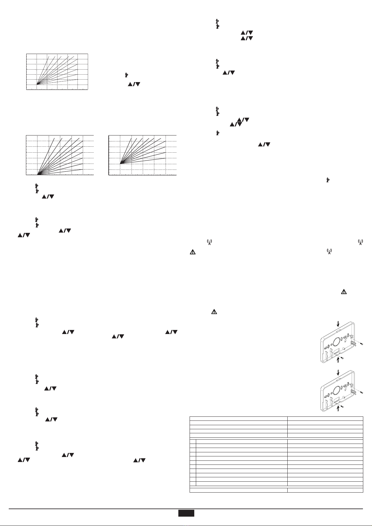
Sliding Temperature - Compensation curve
By installing the external probe (optional), the control system can work with a Sliding Temperature. The external probe must be
connected to the boiler card: refer to the relevant handbook for details. In this mode, the heating system temperature is adjusted
according to the outside weather conditions in order to ensure high comfort and energy saving throughout the year. In particular,
as the external temperature increases the system delivery temperature decreases according to a specific compensation curve.
With the Sliding Temperature adjustment the temperature set through the "Heating temperature adjustment" setting becomes
the maximum system delivery temperature. It is advisable to set a maximum value to allow system adjustment throughout its
useful operating range.
The compensation curve can be set from 1 to 10 according to the following graph.
20
30
40
50
60
70
80
90
85
20 10 0 -10 -20
1
2
3
4
5
68910 7
Temperatura esterna
°C
Temperatura di mandata impianto
°C
1. Keep the button pressed for 3 seconds.
2. The display shows the CU parameter.
Press the buttons to modify the compensation
curve by increments of 1 unit. By keeping the button pressed
the value will change rapidly.
3. Press any other button to exit the menu.
Set the compensation curve to 0 to disable Sliding Temperature adjustment.
The system must be adjusted at the time of installation by qualified personnel. Possible adjustments can in any case be made by
the user to improve comfort. If the room temperature is lower than the required value, it is advisable to set a higher order curve
and vice versa. Proceed by increasing or decreasing in steps of one and check the result in the room.
Sliding Temperature - Parallel curve offset
Once the Compensation curve has been set, parallel curve offset can be adjusted from 20 to 40 as shown in the following
graphs:
20
30
40
50
60
70
80
90
85
20 10 0 -10 -20
1
2
3
4
5
6
8910 7
Temperatura esterna °C
Temperatura di mandata impianto
°C
20 10 0 -10 -20
20
30
40
50
60
70
80
90
85
1
2
3
4
568910 7
°
Temperatura di mandata impianto
°C
1. Keep the button pressed for 3 seconds. 2. The display shows the CU parameter.
3. Press the button . 4. The display shows the OF parameter.
Press the buttons to modify parallel curve offset in 1°C increments. By keeping the button pressed
the value will change rapidly.
5. Press any other button to exit the menu.
Enable DHW programming
Follow the instructions given below to enable domestic hot water programming.
1. Keep the button pressed for 3 seconds. 2. The display shows the CU parameter.
3. Press the button twice. 4. The display shows parameter P1.
Set to 0 using the buttons to disable domestic hot water programming. Set to 1 using the buttons
to enable domestic hot water programming.
5. Press any other button to exit the menu.
To set the weekly automatic programme proceed as described in the section "Step 2. Automatic weekly programme setting",
selecting the tap symbol at step "1" and setting EC (Economy) or CO (Comfort) at step "3" rather than a temperature value. In fact
the remote control has a weekly time programmer based on two levels: during the COMFORT level, the boiler will maintain the set
hot water tank temperature; during the ECO level, the boiler will not deliver domestic hot water. Refer to the boiler documentation
for information on the type of hot water storage tank.
Important: Make sure the remote control is set to Winter mode with automatic operation.
Pre-Heating Function
This function is active only if the automatic heating mode has been selected.
When set to Automatic, the function anticipates the heating system start time (not before 00:00 hours on the same day) so that
the room temperature set by the user is reached at the start of the programmed time band. The Remote Control calculates an
initial hypothetical Pre-activation time: if the programmed room temperature is reached in a shorter time than that calculated, the
Pre-Heating time will be decreased, and vice versa. This creates a self-learning process, for identifying the minimum necessary
Pre-activation time.
The Remote Control also offers the possibility of setting a fixed Pre-Heating slope: In this case, the room temperature will be
increased by 3°C an hour.
Therefore the automatic heating programme should be set according to the time when heat is required and not that when the
heating system is to be started.
Follow the instructions given below to activate or deactivate this function.
1. Keep the button pressed for 3 seconds. 2. The display shows the CU parameter.
3. Press the button 3 times. 4. The display shows parameter P2.
Set to 0 using the buttons
to deactivate Pre-Heating. Set to 1 using the buttons
to
activate Automatic Pre-Heating. Set to 2 using the buttons
to activate the Pre-Heating function
with a fixed slope of 3°C per hour.
5. Press any other button to exit the menu.
During the pre-heating function the room temperature °C symbol flashes.
The pre-heating function ends when the difference between the programmed room temperature and the actual room temperature
is less than 0.5 °C.
Maximum number of daily time bands
The heating programme provides for 6 daily time bands for temperature levels, numbered from 1 to 6. If necessary, the time bands can
be reduced to a minimum of two.
1. Keep the button
pressed for 3 seconds. 2. The display shows the CU parameter.
3. Press the button
4 times. 4. The display shows parameter P3.
Use the buttons
to modify the number of daily time bands from 2 to 6.
5. Press any other button to exit the menu.
Heating minimum temperature
Follow the instructions given below to set the minimum heating circuit water temperature in 1°C steps.
1. Keep the button pressed for 3 seconds. 2. The display shows the CU parameter.
3. Press the button 5 times. 4. The display shows parameter P4.
Use the buttons to adjust the parameter in 1°C increments. By keeping the button pressed
the value will change rapidly.
5. Press any other button to exit the menu.
System filling
This function manages the operation mode of the electric device for filling the water circuit in certain boiler models.
1. Keep the button pressed for 3 seconds. 2. The display shows the CU parameter.
3. Press the button 6 times. 4. The display shows parameter P5.
Set to 0 using the buttons to deactivate the electric filling device. Set to 1 using the buttons
to activate Manual system filling. Set to 2 using the buttons to activate Automatic
system filling.
5. Press any other button to exit the menu.
Important: Set the boiler control card to manual filling. In manual mode, if the sensor installed in the boiler
detects insufficient pressure, the bar icon will flash on the display; press the RESET button to activate the
special solenoid valve. During manual or automatic system filling the bar icon will become fixed. Once the
nominal pressure is restored, the remote control will return to the normal display.
A
B
A
B
External temperature °C
CH supply temperature °CCH supply temperature °C
CH supply temperature °C
External temperature °C External temperature °C


