PREXTHERM
4
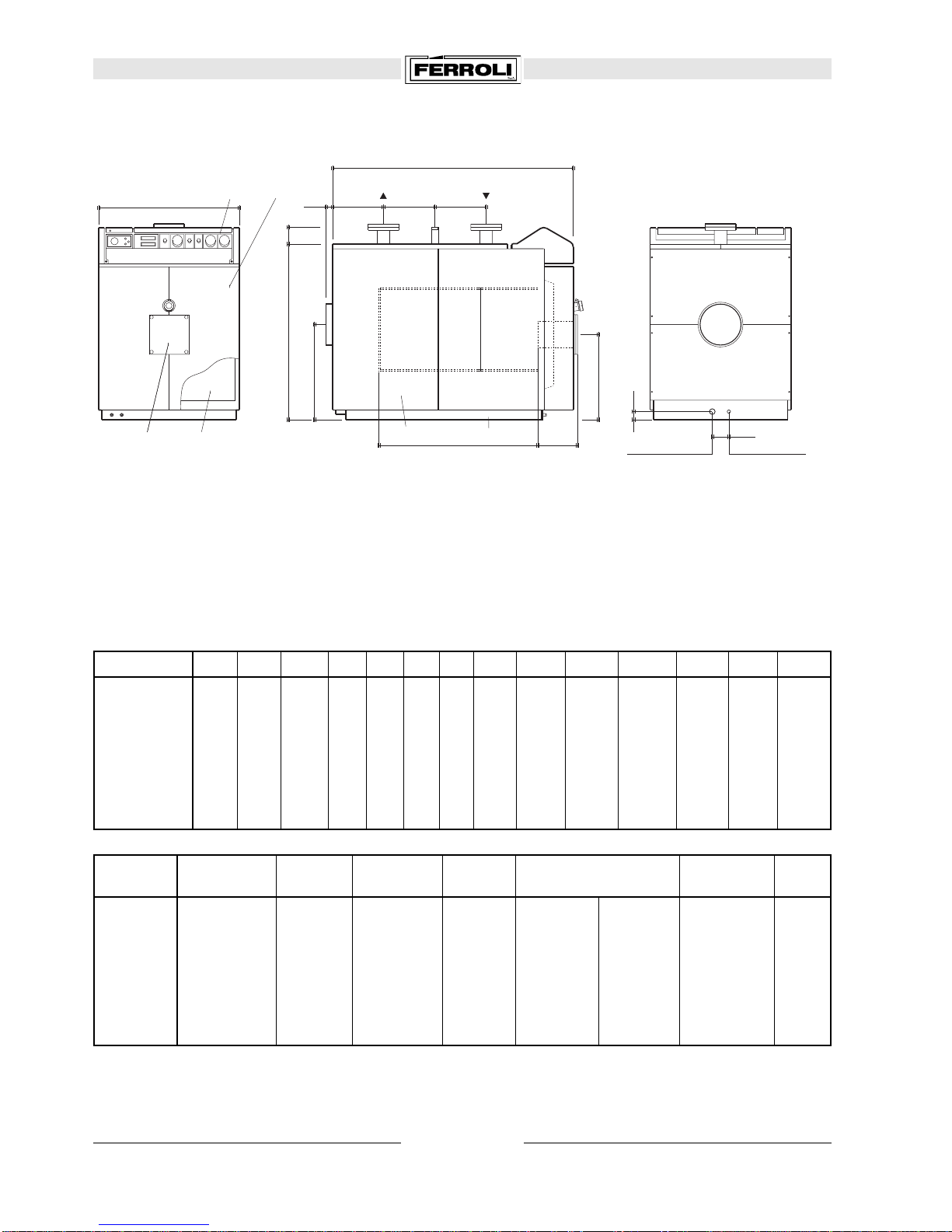
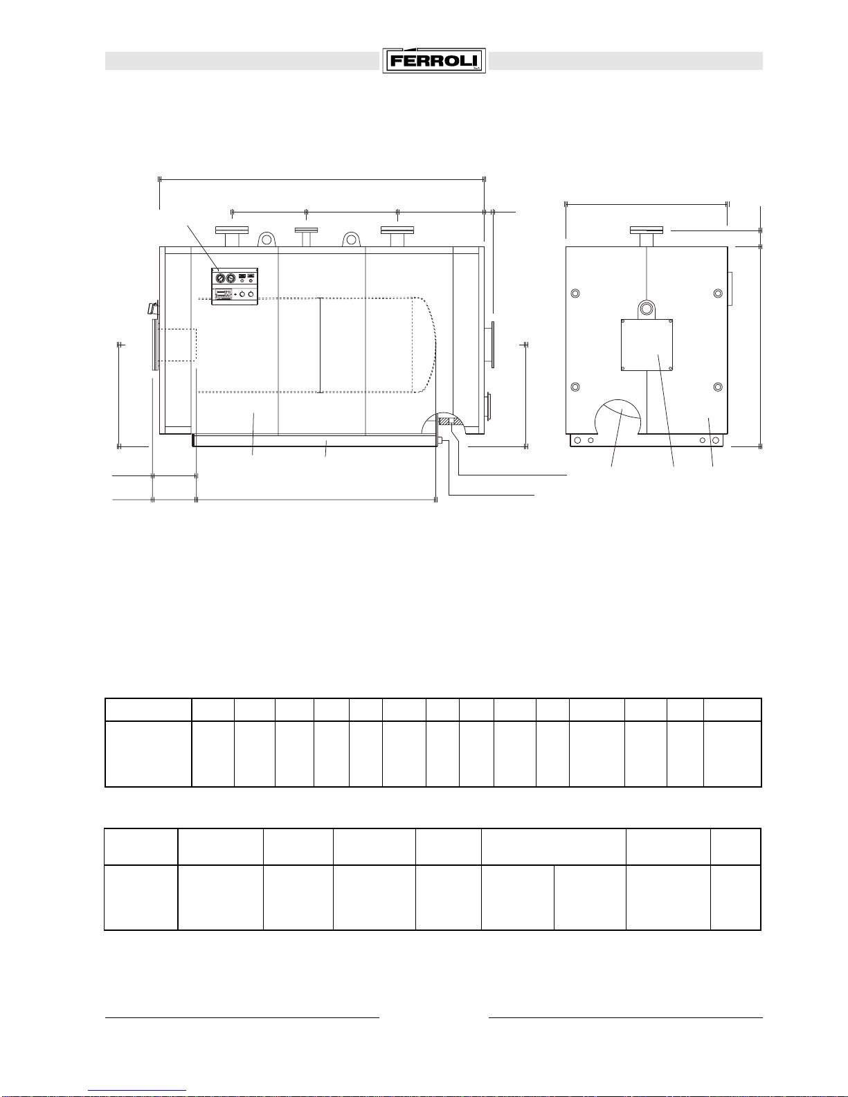
1. DIMENSIONS AND TECHNICAL DATA
A B C D E F G H L M a1 - a2 a3 a4 a5
100 970 760 1110 235 215 145 540 470 660 400 DN 50 1" 1/4 200 160
125 970 760 1260 235 365 145 540 470 810 400 DN 50 1" 1/4 200 160
150 970 760 1410 235 465 195 540 470 960 400 DN 50 1" 1/4 200 160
200 1060 850 1452 306 415 205 585 515 930 480 DN 65 1" 1/4 250 160
250 1060 850 1652 306 515 305 585 515 1130 480 DN 65 1" 1/4 250 160
300 1060 850 1852 306 615 405 585 515 1330 480 DN 65 1" 1/4 250 160
350 1230 1040 1832 484 405 395 670 600 1250 540 DN 80 1" 1/2 300 210
400 1230 1040 2032 484 605 395 670 600 1450 540 DN 80 1" 1/2 300 210
470 1230 1040 2232 484 805 395 670 600 1650 540 DN 80 1" 1/2 300 210
Output kW Input kW Water capac. Pressure drop Working press. Weight
Min. Max. Min. Max. m3dm3*Flue gas mbar **Water mbar bar kg
100 60 100 65 109 0,083 120 0,6 4 5 270
125 75 125 82 136 0,102 142 0,9 7 5 290
150 90 150 98 163 0,124 162 1,1 10 5 320
200 120 200 131 218 0,174 214 0,8 7 5 430
250 150 250 163 272 0,204 247 1,1 10 5 490
300 180 300 196 327 0,241 283 1,4 16 5 560
350 210 350 229 381 0,286 528 1,8 11 5 830
400 240 400 262 436 0,332 598 2,7 15 5 910
470 282 470 307 512 0,378 667 3,6 19 5 980
comb. chamber
volume
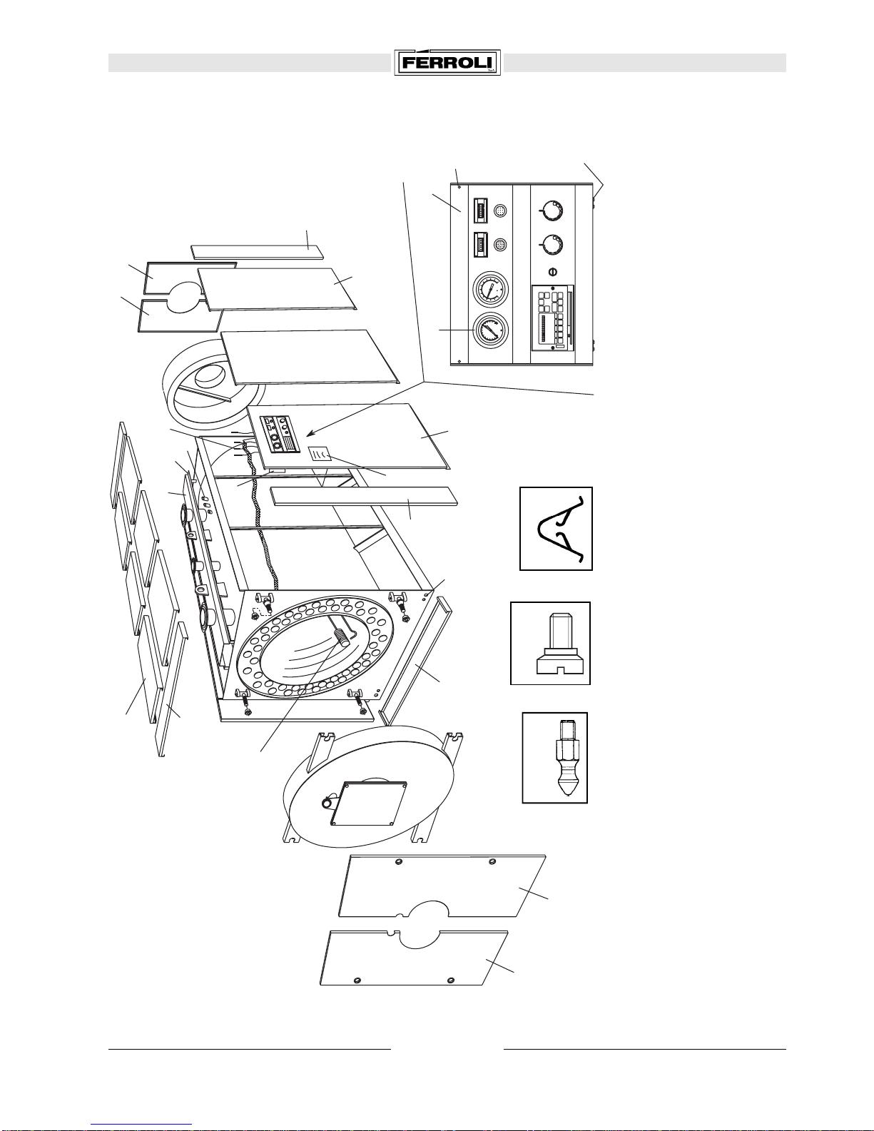
Legend
1Boiler shell
2Door
3Burner mounting plate
4Casing
5Door insulation
6Control panel
a1 Flow connection
a2 Return connection
a3 Safety valve tapping
a4 Flue outlet
a5 Burner flange
PREXTHERM 100-470
PREXTHERM
PREXTHERM
FERROLI
F
a4
a2
100
B
A
100
40
G
D E F
a1 a3
H
a5
C
FLUE CONDENSE
Ø 3/8
DRAIN OFF Ø 1
50
1
4
23
56
L 240
M
Fig. 1
*technical dates for oil-fired heating; for gas heating you must decrease of 15%
**
∆
t considered: 15
°
C