................................
................................
................................
................................
................................
..........................
................................
................................
General safety rules for machine equipment
................................
................................
Safety regulations for hydraulic pres
................................
................................
................................
................................
................................
................................
................................
................................
................................
................................
................................
...............................
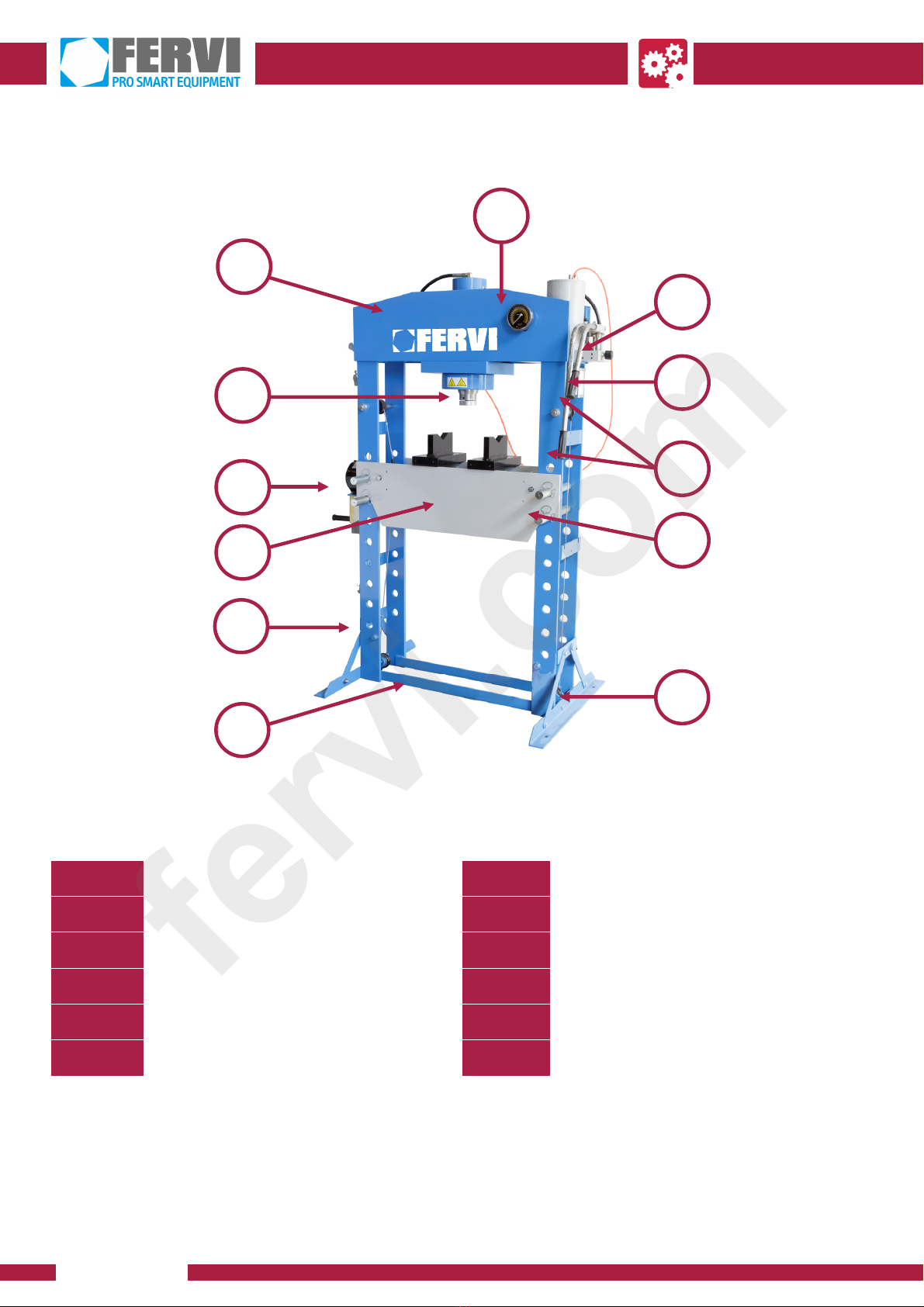
Main parts of the machine
................................
................................
...........................
................................
................................
................................
................................
................................
................................
................................
................................
................................
................................
................................
..........................
................................
................................
................................
................................
................................
...............................
................................
................................
................................
................................
................................
................................
................................
................................
................................
................................
................................
................................
................................
................................
................................
................................
................................
Removing air from the circuit
................................
................................
Pressing work with pneumatic energy
................................
................................
................................
................................
................................
................................
................................
................................
................................
...............................
................................
................................
................................
................................
............................