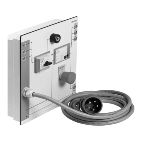
Festo SPC200-PWR-AIF Parts list manual

Kurzbeschreibung
Versorgungsbaugruppe
Typ SPC200-PWR-AIF
Brief description
Power supply module
type SPC200-PWR-AIF
0503b
693 385

Deutsch . . . . . . . . . . . . . . . . . . . . . . . . . . . . . . . . . . . . . . 3
English . . . . . . . . . . . . . . . . . . . . . . . . . . . . . . . . . . . . . . . 11
©(Festo AG & Co., D-73726 Esslingen, 1999)
SPC200-PWR-AIF
0503b 2

1Benutzerhinweise
Die Versorgungs-Baugruppe Typ SPC200-PWR-AIF dient be-
stimmungsgemäß als Versorgungs-Baugruppe für den Smart
Positioning Controller SPC200. Die Versorgungs-Baugruppe
stellt einen Versorgungsanschluß und einen Anschluß für einen
Achsinterface-Strang zur Verfügung.
Ausführliche Informationen zur Versorgungs-Baugruppe finden
Sie im Bediener-Handbuch P.BE-SPC200-....
VORSICHT:
Beachten Sie unbedingt die dort aufgeführten:
– Sicherheitstechnischen Hinweise
– den bestimmungsgemäßen Gebrauch der jeweiligen
Baugruppen und Module.
WARNUNG:
Aktoren können ungewollt aktiviert und der SPC200 beschä-
digt werden, wenn Baugruppen bei eingeschalteter
Spannungsversorgung hinzugefügt oder entfernt werden.
Schalten Sie vor Installations- und Wartungsarbeiten folgen-
de Energiequellen in folgender Reihenfolge ab:
1. Druckluftversorgung
2. Lastversorgung und Betriebsspannungsversorgung des
SPC200.
Deutsch
SPC200-PWR-AIF
0503b 3

2Ein- und Ausbau von Baugruppen
VORSICHT:
Unsachgemäße Handhabung kann zur Beschädigung der
Baugruppen führen.
•Berühren Sie keine Bauelemente.
•Beachten Sie die Handhabungsvorschriften für elektro-
statisch gefährdete Bauelemente.
•Entladen Sie sich vor dem Ein- oder Ausbau von Bau-
gruppen elektrostatisch, zum Schutz der Baugruppen vor
Entladung statischer Elektrizität.
Verschließen Sie freibleibende Steckplätze mit Blindfrontplatten
(Typ SPC-200-PB). Dadurch wird die Schutzart IP 20 erreicht.
Maximal kann eine Versorgungs-Baugruppe in einen Baugrup-
penträger installiert werden.
HINWEIS:
Installieren Sie die Versorgungs-Baugruppe in den ersten
Steckplatz (linker Steckplatz).
Baugruppen ausbauen
1. Druckluftversorgung und Betriebsspannung abschalten.
2. Anschlußkabel auf der Baugruppenfront lösen und abziehen.
2. Beide Sicherungshebel durch Verschieben entriegeln (siehe
folgendes Bild).
3. Baugruppe an der Frontplatte fassen und herausziehen.
4. Ggf. freibleibende Steckplätze mit Blindplatten verschließen.
Deutsch
SPC200-PWR-AIF
40503b

Versorgungs-Baugruppe einbauen
1. Druckluftversorgung und Betriebsspannungsversorgung ab-
schalten.
2. Baugruppe an der Frontplatte fassen und in die erste Füh-
rungsschiene einschieben. Achten Sie darauf, daß Sie die
Baugruppe beim Einschieben nicht verkanten und keine
Bauteile auf der Leiterplatte beschädigt werden.
3. Achten Sie darauf, daß die Stecker der Messerleisten richtig
aufeinander liegen. Schieben Sie die Baugruppe dann mit
leichtem Druck vollständig ein. Daraufhin verriegeln die Si-
cherungshebel selbsttätig.
©
ª
«
Richtung zum Entriegeln
Verriegelt selbsttätig
Sicherungshebel
¬
®
Frontplatte der Baugruppe
Messerleiste
erste Führungsschiene
®
©
¬
ª©
«
«
Deutsch
SPC200-PWR-AIF
0503b 5

3Installation
WARNUNG:
•Verwenden Sie ausschließlich Stromquellen, die eine sichere
elektrische Trennung der Betriebsspannung nach IEC/DIN
EN 60204-1 gewährleisten. Berücksichtigen Sie zusätzlich
die allgemeinen Anforderungen an PELV-Stromkreise ge-
mäß IEC/DIN EN 60204-1.
HINWEIS:
Beachten Sie, daß für die Versorgungs- und Lastspannung
die Toleranz von - 5 % bis + 25 % für beide Stromkreise ein-
gehalten werden muß!
Pin-Belegung des Betriebsspannungsanschluß (X2)
Anschlußquerschnitt max. 1,5 mm2
©
ª
«
¬
24 L: 24 V-Lastversorgung (abschaltbar)
24 V: 24 V-Versorgung interne Elektronik
0 V
Erdungsanschluß
©
ª
¬
«
¬
Deutsch
SPC200-PWR-AIF
60503b

HINWEIS:
Verbinden Sie den Erdungsanschluß des Baugruppenträgers
niederohmig (kurze Leitung mit großem Querschnitt) mit
dem Erdpotential.
Anschlußbeispiel
Das folgende Bild zeigt den Anschluß einer gemeinsamen 24 V-
Versorgung für Pin 1 und Pin 2. Dabei ist zu beachten, daß
–für Last- und Elektronikversorgung die Toleranz von DC
24 V -5 %/+25 % einzuhalten ist
–bei der Lastversorgung zusätzlich die Spannungstoleranzen
der am Achsinterface-Strang angeschlossenen Komponen-
ten zu beachten sind.
©
Lastversorgung abschaltbar
©
0 V 24 V
24 V
0 V
24 L
Deutsch
SPC200-PWR-AIF
0503b 7

Stecker für Achsinterface-Strang (X1)
VORSICHT:
Verwenden Sie zum Anschluß des Achsinterface die speziel-
len Kabel von Festo (Typ KSPC-AIF-...). Beachten Sie be-
züglich der zulässigen Kabellängen am Achsinterface-Strang
die Angaben im Bediener-Handbuch zum SPC200.
Damit vermeiden Sie Funktionsstörungen beim SPC200 und
den am Achsinterface-Strang angeschlossenen Modulen.
Über den 5poligen Stecker der Versorgungsbaugruppe werden
die Bussignale, die Betriebsspannung und die Lastversorgung
für die angeschlossenen Feldgeräte bereitgestellt.
Das Anschlußkabel KSPC-AIF-... wird vorkonfektioniert mit
5poliger Schraubklemme geliefert.
VORSICHT:
Der Achsinterface-Anschluß ist nicht gegen Verpolung ge-
schützt. Achten Sie unbedingt auf die korrekte Belegung,
wenn Sie z.B. nach Kürzen des Kabels die Schraubklemme
selbst anbringen.
HINWEIS:
Kennzeichnen Sie die am SPC200 angeschlossenen Kabel.
Damit vermeiden das Verwechseln baugleicher Stecker bei
Umbauarbeiten.
Deutsch
SPC200-PWR-AIF
80503b

Pin-Belegung und Adernfarben des Kabels Typ KSPC-AIF-...
©
ª
«
CAN-LOW (braun)
CAN-HIGH (weiß)
24 V (gelb)
¬
®
0 V (grün)
24 V Lastversorgung (grau)
Erdungsanschluß
Schließen Sie den Kabelschirm an den Erdungsanschluß (
®
)
an.
4Technische Daten
Typ SPC200-PWR-AIF
Temperaturbereich:
– Betrieb
– Lagerung/Transport
- 5
oC ... + 50 oC
-20 oC ... + 70 oC
Gewicht 82 g
Relative Luftfeuchtigkeit 95 % nicht kondensierend
Betriebsspannung Pin 1
(Lastversorgung)
– Nennwert
– Toleranz 1)
– Restwelligkeit
– Stromaufnahme
(SPC200-CPU-4 und ...-6)
DC 24 V
-5 %...+25 % (22,8 V ... 30,0 V)
2 %
500 mA + 1,2 A je Pneumatische Achse
ª
«
©
¬
®
®
Deutsch
SPC200-PWR-AIF
0503b 9

Fortsetzung Technische Daten Typ SPC200-PWR-AIF
Betriebsspannung Pin 2
(interne Elektronik)
– Nennwert
– Toleranz 1)
– Restwelligkeit
– Netzausfallüberbrückungszeit
– Stromaufnahme bei:
SPC200-CPU-4
SPC200-CPU-6
DC 24 V
-5 %...+25 % (22,8 V ... 30,0 V)
2 %
10 ms
400 mA + Strombedarf der an der
Sensorversorgung angeschlossenen
Komponenten 2) + Summe Stromauf-
nahme am AIF-Strang 3)
600 mA + Strombedarf der an der
Sensorversorgung angeschlossenen
Komponenten 2) + Summe Stromauf-
nahme am AIF-Strang 3)
Schutz gegen elektrischen Schlag
(Schutz gegen direktes und indi-
rektes Berühren nach IEC/DIN
EN 60204-1)
durch PELV-Stromkreis
(Protective Extra-Low Voltage)
Elektromagnetische
Verträglichkeit
– Störaussendung
– Störfestigkeit
geprüft nach
DIN EN 61000-6-4 (Industrie) 4)
geprüft nach
DIN EN 61000-6-2 (Industrie)
Schwingung und Schock
– Schwingung
– Schock
geprüft nach DIN/IEC 68 Teil 2–6
Schärfegrad 1
geprüft nach DIN/IEC 68 Teil 2–27
Schärfegrad 2
1) Toleranz der am Achsinterface-Strang angeschlossenen Module beachten!
2) Je E/A-Baugruppe Typ SPC200-DIO können max. 0,5 A bereitgestellt werden
3) Siehe Technische Daten der angeschlossenen Module
4) Die Komponente ist vorgesehen für den Einsatz im Industriebereich.
Deutsch
SPC200-PWR-AIF
10 0503b
1User instructions
The type SPC200-PWR-AIF power supply module is designed
to supply power to the SPC200 Smart Positioning Controller.
The power supply module has a connection for the power sup-
ply and a connection for an axis interface string.
More detailed information about the power supply module can
be found in the User Manual P.BE-SPC200-....
CAUTION
Pay strict attention to the following instructions shown
therein:
– safety guidelines
– specifications for the use of each module and component.
WARNING
Actuators can be accidentally activated and the SPC200
damaged if modules are either inserted or removed with the
power switched on.
Before installation or maintenance work switch off the
following power sources in the following order:
1. Compressed air supply
2. The load supply and operating voltage supply of the
SPC200.
English
SPC200-PWR-AIF
0503b 11

2Fitting and removing the modules
CAUTION
Modules can be damaged by incorrect handling.
•Do not touch any of the components.
•Follow the instructions for handling components which
are affected by electrostatic charges.
•Discharge yourself electrostatically before inserting or
removing modules in order to protect the components from
discharges of static electricity.
Fill any remaining empty slots with blank front panels (type
SPC-200-PB). This satisfies the requirements of the IP 20 pro-
tection system. No more than one power supply module can be
installed in the rack.
PLEASE NOTE
Mount the power supply module in the first (left-hand) slot.
Removing the modules
1. Switch off the power and compressed air supply.
2. Disconnect the cable on the front of the module and remove
it.
2. Slide the two safety catches sideways to unlock them
(see diagram below).
3. Take hold of the module by the front plate and extract it.
4. Fill any remaining empty slots with blank panels.
English
SPC200-PWR-AIF
12 0503b

Fitting the power supply module
1. Switch off the compressed air supply and operating voltage
supply.
2 Take hold of the front plate of the module and slide it into the
first guide rail. Be careful not to tilt the module when sliding
it into the slot, and make sure that none of the components
on the board are damaged.
3. Make sure that the pins on the connectors are correctly
aligned. Then with a light pressure of the fingers push the
module fully home. The safety catches will then lock auto-
matically.
©
ª
«
Direction of unlocking
Self-actuated locking
Safety catches
¬
®
Front plate of module
Contact strip
First guide rail
®
©
¬
ª©
«
«
English
SPC200-PWR-AIF
0503b 13

3Installation
WARNING
•Use power supplies which guarantee reliable electrical isola-
tion of the operating voltage as per IEC/DIN EN
60204-1. Consider also the general requirements for PELV
circuits in accordance with IEC/DIN EN 60204-1.
PLEASE NOTE
Remember that the tolerance limits of -5 % to +25 % for the
supply and load voltages apply to both circuits.
Pin assignment of the operating voltage input (X2)
Connector cross section area max. 1.5 mm2
©
ª
«
¬
24 L: 24 V load supply (switchable)
24 V: 24 V supply for internal circuits
0 V
Earth connection
©
ª
¬
«
¬
English
SPC200-PWR-AIF
14 0503b

PLEASE NOTE
Make a low-impedance connection (short lead of large
diameter) between the earth connection of the rack and
earth potential.
Connection example
The following illustration shows the connections to pin 1 and pin
2 of a common 24 V supply. Note that:
–the tolerance limits for the load supply and circuit supply
must not exceed 24 V DC -5 % +25 %;
–in the case of the load supply, the voltage tolerances for the
components connected to the axis interface string must also
be observed.
©
Load supply switchable
©
0 V 24 V
24 V
0 V
24 L
English
SPC200-PWR-AIF
0503b 15

Connector for the axis interface string (X1)
CAUTION
Use Festo special cable (type KSPC-AIF-...) for connecting
the axis interface. Please refer to the SPC200 User Manual
for details of permitted cable lengths for connecting the axis
interface string.
Failure to observe the correct cable lengths could lead to mal-
function of the SPC200 and the modules connected to the axis
interface string.
The bus signals, the operating voltage and the load supply for
the peripheral devices are provided via the 5-pin connector on
the power supply module.
The KSPC-AIF-... connecting cable is supplied prefitted with a
5-pin screw terminal.
CAUTION
The axis interface connection does not have protection
against incorrect polarity. Make sure that the contacts are
correctly assigned if, for example, you connect the screw
terminal yourself after shortening the cable.
PLEASE NOTE
Mark the cables connected to the SPC200.
In this way you can avoid confusion with similar plugs during
conversion work.
English
SPC200-PWR-AIF
16 0503b

Pin assignment and wire colours of cable type KSPC-AIF-...
©
ª
«
CAN-LOW (brown)
CAN-HIGH (white)
24 V (yellow)
¬
®
0 V (green)
24 V Load supply (grey)
Earth connection
Connect the cable screening to earth connection (
®
).
4Technical specifications
Type SPC200-PWR-AIF
Temperature range:
– operating
– storage/transport
- 5
oC ... + 50 oC
-20 oC ... + 70 oC
Weight 82 g
Relative humidity 95 % non-condensing
Operating voltage pin 1
(Load supply)
– nominal value
– tolerance 1)
– residual ripple
– current consumption
(SPC200-CPU-4 and ...-6)
24 V DC
-5 %...+25 % (22.8 V ... 30.0 V)
2 %
500 mA + 1.2 A for each pneumatic axis
ª
«
©
¬
®
®
English
SPC200-PWR-AIF
0503b 17

Technical specifications (continued) type SPC200-PWR-AIF
Operating voltage pin 2
(internal circuitry)
– nominal value
– tolerance 1)
– residual ripple
– power failure bridging time
– current consumption with:
SPC200-CPU-4
SPC200-CPU-6
24 V DC
-5 %...+25 % (22.8 V ... 30.0 V)
2 %
10 ms
400 mA + current requirement of
components connected to sensor
supply 2) + sum of current consumption
on AIF string 3)
600 mA + current requirement of
components connected to sensor
supply 2) + sum of current consumption
on AIF string 3)
Protection against electric shock
(protection against direct and indi-
rect contact as per IEC/DIN EN
60204-1)
by means of PELV circuits
(Protective Extra-Low Voltage)
Electromagnetic compatibility
– Interference emitted
– Immunity against interference
Tested as per
DIN EN 61000-6-4 (industry) 4)
Tested as per
DIN EN 61000-6-2 (industry)
Oscillation and shock
– oscillation
– shock
tested as per DIN/IEC 68 Part 2–6
severity class 1
tested as per DIN/IEC 68 Part 2–27
severity class 2
1) Observe the tolerance of the modules connected to the axis interface string
2) Max. 0.5 A can be made available for each I/O module type SPC200-DIO
3) See technical specifications of the connected modules
4) The component is intended for industrial use
English
SPC200-PWR-AIF
18 0503b
Table of contents
Languages:
Other Festo Power Supply manuals

Festo
Festo EduTrainer 571812 User manual

Festo
Festo CPX-EPL-EV-S User manual

Festo
Festo EduTrainer Compact User manual

Festo
Festo EduTrainer 567321 User manual

Festo
Festo VMPAF-FB-SP Series User manual

Festo
Festo 8049382 User manual

Festo
Festo MS4-E-IPM-80-80 User manual

Festo
Festo SVG-1/230VAC-48VDC-10A Quick start guide

Festo
Festo SVG-1/230VAC-24VDC-5A Quick start guide