Fetco CBS-71A Specifications

www.fetco.com
User’s Guide and Operator Instructions
CBS-71A & AC & CBS-72A & AC High Volume Drip Coffee & Tea Brewers
FETCO Commercial Beverage Equipment
CBS-71A; CBS72A CBS71AC; CBS72AC
Shown with LBD-6 dispensers, sold separately Shown with LBD-6C mobile cart dispensers, sold separately
This user guide describes the CBS-71 and CBS-72 models manufactured after 2014.
For older digital CBS-7000 models: refer to FETCO user guide P022 which includes the steam operated models and models with transfer option.
For analog CBS-71 and CBS-72 models built before 2005: refer to FETCO user guide P006
Contact Information
FETCO®
Food Equipment Technologies Company
600 Rose Road
Lake Zurich • IL • 60047-1560 • USA
© 1998-2019 Food Equipment Technologies Company
Internet: www.fetco.com
Phone: (800) 338-2699 (US & Canada)
(847) 719-3000
Fax: (847) 719-3001
Email: [email protected]
techsupport@fetco.com
CBS-7000 High Volume -Six Gallon Drip Coffee &Tea Brewer Series
P186 January 2020
fetco.com

Go to fetco.com for the latest versions of all information Page 2CBS-7000 Series Brewers & Dispensers P186 JANUARY 2020
Table of Contents
Weights and Capacities .............................................2
Electrical Configuration and Brewing Efficiency.........3
Rough-in drawings .....................................................4
Installation ..................................................................5
Power Management System......................................6
Operating Procedures ................................................7
Brewing System .........................................................7
Programming..............................................................8
Cleaning & Maintenance............................................9
Parts.........................................................................10
Dispensers ...............................................................18
Weights and Capacities
Product Description/Features
Six gallon per batch brewers
CBS
- 71A - Single Brewer
Stationary:
to be mounted on counter or stand
CBS-72A - Twin Brewer
Stationary: to be mounted on counter or stand
CBS
-71AC - Single Brewer
With stand: f
or use with mobile dispensers
CBS-72AC - Twin Brewer
With stand: for use with mobile dispensers
A and AC versions are identical units. The only difference is the “A” unit is placed on a stand or counter
Large volume insulated dispensers
Required for use with CBS-70 brewers
LBD
-6, six gallon counter-top dispenser
Use with models CBS-71A and CBS-72A (2 required)
LBD-6C mobile six gallon dispenser cart
Use with models CBS-71AC and CBS-72AC (2 required)
LBD
-18 Mobile 18 gallon dispenser cart,
use with CBS
-72AC models only
LBD-24 Mobile 24 gallon dispenser cart,
use with CBS-72AC models only
Features
Tight fitting brew baskets seal in flavor and steam.
Optional Features:
Fully automatic, with electronic temperature control.
•
Power management*
Will not brew unless brewing water temperature is correct.
•
Custom and export voltage
Thermal breakers and high pressure cutoff switch for safety.
Total serviceability from the front and top.
Portable, thermal stainless steel dispensers, 6, 18, or 24 gallons.
* Factory installed
Specifications
Brew Volume: 6 gallons (22.7 liters)
(Not adjustable)
Average Brew Time: 7 minutes
(Allow an extra 3-5 minutes for coffee to finish dripping)
Water Requirements: CBS-71: 1½ gpm, 20-75 psig
Coffee Filters: 23” X 9” FETCO # F006
CBS-72: 3 gpm, 20-75 psig
Electrical: See electrical configuration chart.
Required Dispensers: Minimum 6 gallon
(18 or 24 gallon mobile cart dispensers available)
Brewer
Water
Tank
Total
Weight,
Dispenser
Weight
Total
Weight,
Model
Weight
Capacity
Weight
filled
Model
(empty)
Capacity
filled
CBS-71A
239 lbs.
18 gal.
150 lbs.
389 lbs.
LBD-6
40 lbs.
6 gal.
90 lbs.
CBS-72A/AT
420 lbs.
2 X 18 gal.
300 lbs.
720 lbs.
LBD-6C
152 lbs.
6 gal.
202 lbs.
LBD-18
228 lbs.
18 gal.
378 lbs.
LBD-24
222 lbs.
24 gal.
422 lbs.
LBD-60
227 lbs.
60 gal.
726 lbs.

Go to fetco.com for the latest versions of all information Page 3CBS-7000 Series Brewers & Dispensers P186 JANUARY 2020
Electrical Configuration and Brewing Efficiency
CBS-71A & AC 6.0 gallons per batch (max 5 per hour)
CBS-72A & AC 6.0 gallons per batch (max 5 per hour-per side)
Heater
Voltage
Maximum
Gallons per Hour
Model
SKU.
Configuration
Connection
Phase
Wires
KW
Amp draw
Maximum: 36
CBS-71A (-1) C71017 3 X 5 KW 120/208 3 ph. 4+ground 11.5 33.0
CBS-71AC (-1)
C71018
120/220
3 ph.
4+ground
13.3
36.0
18-24
120/240
3 ph.
4+ground
15.2
37.9
CBS-71A (-2) C71027 3 X 10 KW 120/208 3 ph. 4+ground 22.7 64.3
CBS-71AC (-2)
C71028 120/220 3 ph. 4+ground 26.3 70.3 36
120/240
3 ph.
4+ground
30.2
74.0
CBS-71A (-3) C71037 3 X 10 KW 120/480 3 ph. 4+ground 30.2 37.9 36
CBS-71AC (-3)
C71038
3 X 10 KW
120/480
3 ph.
4+ground
30.2
37.9
“A” suffix is stationary counter mount; “AC” is mounted on a stand for use with a mobile cart. otherwise, the versions are identical units
The differences in “A” and “AC” are the counter or stand upon which the unit is placed.
Based on standard factory settings:
7 minute brew time, 200°F water
No drip delay
CBS-71A and CBS-72A stationary six gallon gourmet brewer CBS71 A & CBS-72A shown on optional A019 & A020 counter CBS-71AC & CBS-72AC shown with stand for use with mobile dispensers
CBS-71A & 72A shown with optional LBD-6 dispensers-purchase separately item D019 CBS-71AC & 72AC shown with optional LBD-6 mobile dispensers-purchase item D020
Heater
Voltage
Maximum
Gallons per Hour
Model
Configuration
Connection
Phase
Wires
KW
Amp draw
Maximum: 60
CBS-72A (-1)
C72017
3 X 5 KW
120/208
3 ph.
4+ground
11.6
33.7
CBS-72AC (-1)
C71018
on each side
120/220
3 ph.
4+ground
13.4
36.7
24-36
With Power Management
120/240
3 ph.
4+ground
15.3
38.6
CBS-72A (-2)
C72027
3 X 5 KW
120/208
3 ph.
4+ground
22.8
65.0
CBS-72AC (-2)
C71028
on each side
120/220
3 ph.
4+ground
26.4
71.0
36-42
Without Power Management
120/240
3 ph.
4+ground
30.3
74.7
CBS-72A (-3)
C72037
3 X 10 KW
120/208
3 ph.
4+ground
22.8
65.0
CBS-72AC (-3)
C72038
on each side
120/220
3 ph.
4+ground
26.4
71.0
54-60
With Power Management 120/240 3 ph. 4+ground 30.3 74.7
CBS-72A (-4) C72047 3 X 10 KW 3+ground
CBS-72AC (-4)
C72048
on each side
120/480
3 ph.
(plus 120V
30.3
37.9
60
With Power Management Cord & plug)
CBS-72A (-5)
C72057
3 X 10 KW
3+ground
CBS-72AC (-5) C72058 on each side 120/480 3 ph. (plus 120V 60.3 74.7 60
Without Power Management
Cord & plug)
-Each CBS-72 is actually two separate brewers in one body. Each side has a separate water tank and 3 heaters.
-The power management feature allows only one side of the brewer to heat at any given time, which limits the total
amperage required for operation. Power management option must be installed by factory.
Based on standard factory settings:
7 minute brew time, 200°F wa
ter
No drip delay

Go to fetco.com for the latest versions of all information Page 4CBS-7000 Series Brewers & Dispensers P186 JANUARY 2020
Rough-in drawings
CBS-72AC CBS-72AC & CBS-71AC [si d e ) CBS-71AC
CBS-72AC fixture placement CBS-71AC fixture placement
CBS-72A CBS-72A [Dispenser drawer opening for all CBS-70 models] CBS-71A
CBS-72A fixture placement CBS-71A fixture placement
CBS-71A and CBS-72A Rough-in drawings
CBS-71AC and CBS-72AC Rough-in

Go to fetco.com for the latest versions of all information Page 5CBS-7000 Series Brewers & Dispensers P186 JANUARY 2020
Installation
(For Qualified Service Technicians Only)
Keys To A Successful Installation
If not installed correctly by qualified personnel, the brewer will not operate properly and damage may result.
Damage resulting from improper installation is not covered by the warranty.
Here are the key points to consider before installation:
Electrical:
•All FETCO brewers require NEUTRAL. Ground is not an acceptable substitute. Installation without neutral
may cause damage to the electronic components.
•The power connection to L1 on the terminal block must be at least 105 volts. Less than 105 volts will
cause erratic behavior from the brewer.
•Push button circuit breakers are located on the front of the brewer, behind the dispensers.
Plumbing:
•This equipment is to be installed to comply with the applicable federal, state, or local plumbing codes.
•The water line must be flushed thoroughly prior to connecting it to the brewer to prevent debris from
contaminating the machine.
General:
•Utilize a qualified beverage equipment service technician for installation.
Brewer Installation
The installation must comply with applicable federal, state, and local codes having jurisdiction at your location.
Check with your local inspectors to determine what codes will apply to the installation and operation of FETCO
products.
Brewer Set-up
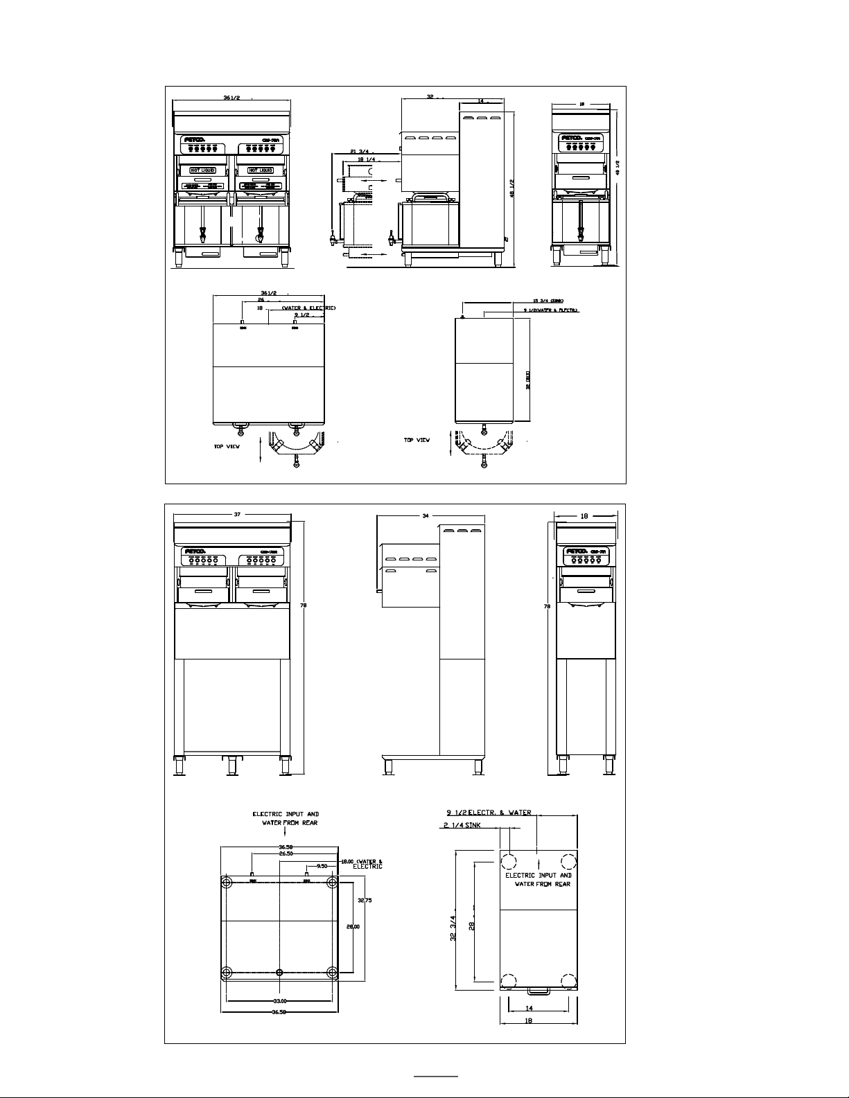
•Place the brewer stand (for mobile cart systems) or counter (for stationary systems) in the desired location.
Allow at least 1 foot of space between the wall and the back of the stand or counter.
For easy access and visibility, electrical shut off switches, circuit breakers, water valves, and filters should
not be located directly behind the brewer.
•Using a carpenter’s level, adjust the legs until the stand or counter is perfectly level front-to-back, and left-
to-right.
•Each leg has a flange with 2 holes for bolting the stand or counter to the floor (required for safety). Mark
the location of the holes on the floor.
•Set the stand or counter aside, and drill holes in the floor as marked. The materials used will depend on
the floor material.
•Bolt the stand or counter to the floor, and double check to make sure it is level.
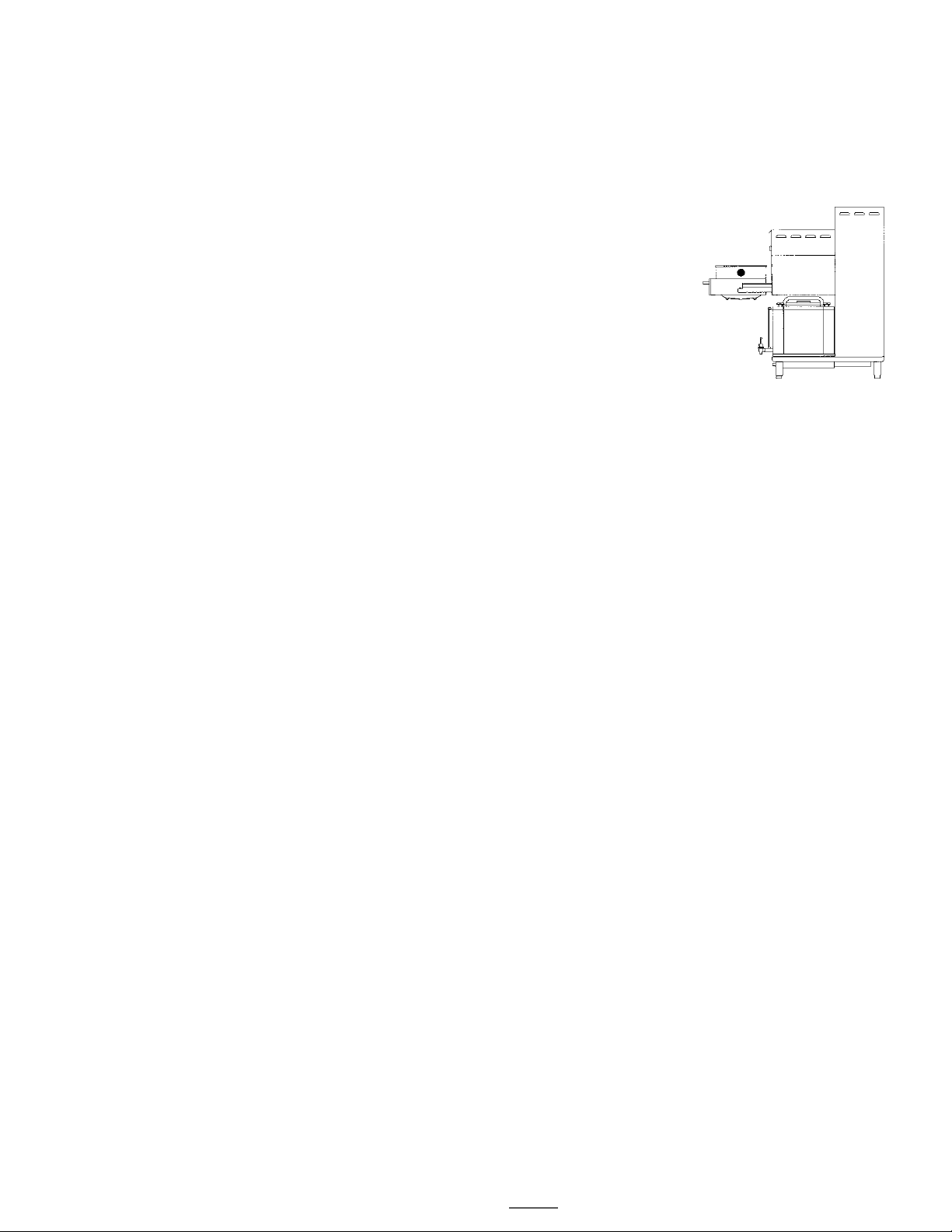
•The brewer is shipped lying on its’ back. Before standing it upright, remove the front cover. There is no
need to remove the 2 top covers.
•Place the brewer on top of the stand or counter. This requires at least 3 people, 4 if possible.
•Bolt the brewer to the stand or counter, using the nuts and bolts provided.
Drip Tray Drain Connection (stationary systems only)
•A kitchen sink style drain is provided on the drip tray for connection to a 1 ½ inch drain pipe.
•Before connecting the drain, the customer should select one of the three available height positions for
mounting the drip tray. Holes are provided in the back of the counter for each of the available positions.
Water connection
•Caution! The hose barb fitting(s) protruding from the back of the unit are the tank drains. DO NOT connect
the incoming water to these fittings.
•The water connection is a single 3/8 inch male flare fitting, located inside the lower compartment.
•The brewer can be connected to a cold or hot water line. Cold water is preferred for best coffee flavor, but
hot water will allow for faster recovery times.
•Install a water shut off valve near the brewer to facilitate service. If an in-line water filter is used, it should
be installed after the water shut off valve and in a position to facilitate filter replacement.
•Before connecting the water line to the brewer, flush the line and water filter thoroughly to remove any
debris.
•Connect the water line to the brewer, and turn on the water to check for leaks.

Go to fetco.com for the latest versions of all information Page 6CBS-7000 Series Brewers & Dispensers P186 JANUARY 2020
Electrical connection
•Verify that the actual voltage at the electrical service connection is compatible with the specifications on the
brewer’s serial number plate. Make sure the electrical service includes neutral.
•A fused disconnect switch or circuit breaker on the incoming power line must be conveniently located near the
brewer, and its location and markings known to the operators.
•The body of the brewer must be grounded to a suitable building ground. A ground lug is provided in the brewer
next to the power terminal block. Use only 10 gauge copper wire for grounding.
•Make sure that both power switches are in the “off” position. The buttons should be in the “out” position.
•Connect the power, neutral, and ground wires to the terminals in the brewer.
TERMINAL BLOCK
GROUND
WIRE
L1
L2
L3
N
120V
208-240V
208-240V
208-240V
GROUND
LUG
1
2
3
CORD WITH 5-15P
NEMA PLUG
TERMINAL BLOCKS
GROUND
LUG
GROUND
WIRE
L1
L2
L3
480 V
480 V
480 V
GROUND
LUG
TO 120V OUTLET
Electrical Connection - 240 volts, 3 phase
Electrical Connection - 480 volts, 3 phase
•Turn on the building circuit breaker. Do not turn on the brewer’s power switches yet.
•At the brewer’s terminal block, verify that the correct voltage is between terminals, according to the diagram
above.
•CBS-71A - press the power switch. CBS-72A - press only the power switch on the brewer’s left side. The power
switch will illuminate. After a delay of 5-6 seconds, the tank should begin filling with water.
•CBS-72A - You can press the right side power switch at any time to begin filling the other tank, but this will cause
the first tank to fill more slowly. To fill the first tank as fast as possible, wait until it has filled completely before
pressing the right side power switch.
•The heating process will begin after the water has reached a safe level, but before the tank has filled completely.
Approximately 10-15 minutes after the tank has filled, the ready light will illuminate, indicating that this side of the
brewer is at the proper temperature and ready to operate.
Power Management System
Available only as factory installed for CBS-72 (dual) models
Power management operates one side of the CBS-72 tank heaters. High amperage power requirement is
reduced with power management by not operating both sides tank heaters. When brew is started, power to
heaters is turned off on the brewing side and only operates the on the other, not-brewing, side if needed. If
brew “START” is activated while the tank is heating, the ready light flashes while tank heats to the setpoint.

Go to fetco.com for the latest versions of all information Page 7CBS-7000 Series Brewers & Dispensers P186 JANUARY 2020
Operating Procedures
Brewing System
Before brewing, always verify the cleanliness of the brew baskets and dispensers.
1. Push the POWER switch to the ON position
•The button will illuminate to indicate that the brewer has power and is operational.
2. Prepare the brew basket(s).
•Carefully pull open the drawer holding the brew basket.
•Grasp the brew basket by one handle, and turn it until you can reach both
handles comfortably.
•Grasp both handles and lift the basket out of the drawer. If necessary,
empty and rinse the brew basket.
•Place a paper filter in each basket to be used. Pour the appropriate
amount of pre-measured, ground coffee into the filter. Spread the coffee
evenly in the basket until it is a uniform depth. (The amount of coffee used
will depend on your personal tastes and the recommendation of your
coffee supplier.)
•Place the brew basket back into the drawer. Turn the brew basket to align either one of the handles
with either front corner of the drawer.
•Close the drawer completely. When fully closed, it will be flush with the front surface of the brewer.
3. Place the appropriate dispenser(s) in position under the brew baskets.
•Ensure that the brew-through cover is in place, the dispenser is empty enough to handle the amount of
coffee to be brewed, and the faucets are closed.
•Ensure that the dispensers are pushed all the way in, and that the brew funnels are aligned with the
bottom of the brew baskets.
•When using carts, always set both parking brakes by pressing your foot on the paddle just above each
of the two wheels closest to you. When the brakes are set, a green button extends above the paddle.
To release the brakes for moving, press the green button with your foot.
4. When the READY light is on, press the BREW button to start the brew cycle
•The brew cycle will begin immediately, and the BREW button will illuminate. The brew cycle cannot be
started unless the READY light is on.
•Drip delay: When the brew cycle is finished, the BREW button will flash during the drip delay cycle,
indicating that coffee may still be dripping from the bottom of the brew basket.
Optional BREW WAIT setting (See Programming section)
•If the BREW WAIT setting is ON, and the READY light is off when the brew button is pressed, the
BREW and READY lights will begin flashing. When the water has heated to the proper temperature,
the READY light will go on, the brew cycle will begin, and the BREW button will illuminate with a steady
glow.
•If necessary, you may stop the brew cycle at any time by pressing the STOP button. This will reset the
brewer, and you will have to start a new brew cycle from the beginning.
.CAUTION:
•Do not remove the brew basket or move the dispensers immediately after the brew cycle has
finished. Wait until dripping from the bottom of the brew basket has stopped. This may take
several minutes.
•When removing the brew basket, carefully inspect the inside of the basket for hot coffee that
may have been trapped or has not finished draining.
•Always set both parking brakes whenever carts are not being transported.

Go to fetco.com for the latest versions of all information Page 8CBS-7000 Series Brewers & Dispensers P186 JANUARY 2020
Programming
Turn the power switch on.
CONTROL BOARD
Display
Hold the SET button for 3 seconds, until the display reads SET.
SET
The display will show 0.0 briefly,
0.0
followed by the software version. Example: 10.A
10.A
The display shows the
actual water temperature
when not in Programming
mode.
Press SET. The first parameter number will be displayed briefly,
1.0
followed by the current setting.
312
Example: 1.0 = Brew orifice, .312”
Use the UP and DOWN buttons to adjust the setting.
Press SET again. The next parameter will be displayed briefly,
1.1
followed by the current setting.
0
Example: Bypass percent, 0%
Use the UP and DOWN buttons to adjust the setting.
Continue this way until all parameters are programmed.
See the chart below for an explanation of each parameter.
Important! To save your changes and return to operating mode,
you must hold SET for 3 seconds until the display reads STo.
STo
The unit will automatically return to normal operating mode after 30
seconds without programming activity, and changes will not be saved.
Parameter Name Range Increment
Standard Factory
Setting
1
Comment
0.0
Software Version
Displays current version.
1.0
Brew orifice size
Five available
sizes: .250,
.281, .312,
.343, .375.
.312
This is the size of the hole in
the brew orifice, which
controls how fast water is
dispensed.
2
1.1
Bypass Percent
0.00 – 35.0%
5%
0 %
Percentage of total brew
volume.
1.2
Drip Delay
(Min:Sec)
1 – 5 minutes
10 sec.
1:30
Time between the end of the
brew cycle and the brew light
stops flashing.
1.3
Auto Transfer Pump
1 – 6 minutes
10 sec.
4:00
Transfer units only.
This is the amount of time the
transfer pump runs after a
brew cycle when the “Auto
Transfer” switch is on.
2.0
Water Temp. (°F)
180°F - 208°F
1°F
205°F
3.0
Brew Wait
ON - OFF
OFF
OFF = Brewer must be at set
temperature (READY light on)
to start a brew cycle.
ON = If the BREW button is
pressed when the unit is not
at the set temperature, the
brewer will wait until it heats
up, and then begin brewing.
The READY and BREW lights
flash during the waiting time.
1Standard factory settings apply unless custom settings were requested at the time of order.
2Non-standard size brew orifices must be ordered from FETCO.
Error Codes
050 - Shorted Temp Probe
051 - Open Temp Probe
070 - Stuck switch
(Switch stuck or held in for
more than 45 seconds.)
Error codes are displayed
on the control board.
To reset, turn the power
switch off and on.

Go to fetco.com for the latest versions of all information Page 9CBS-7000 Series Brewers & Dispensers P186 JANUARY 2020
Cleaning & Maintenance
Daily
Before brewing, always verify the cleanliness of the brew baskets and dispensers.
At the end of the day, remove the brew basket and wipe the bottom of the spray pan with a cloth to remove the
coffee oils that have collected.
Brew & Bypass Orifices
The flow of water through the brew and bypass orifices may gradually become restricted by the accumulation of
mineral deposits. The orifices should be inspected periodically and cleaned if necessary.
To remove the orifices:
* Remove the brew basket and brew basket drawer.
*Grasp the sides of the spray pan with both hands and turn it counter-clockwise. Being careful not to drop
it, continue turning it with both hands until it comes completely off.
*The brew orifice is located in the center of the threaded piece that held the spray pan. The bypass orifice
is located to the right and to the rear of the brew orifice. Both orifices are stainless steel. Do not remove
the brass fitting located in the same area. This is the vent from the water tank.
*Removal of either orifice requires a 11/16 inch wrench.
*Replace or clean the orifices and reassemble all of the parts.

Go to fetco.com for the latest versions of all information Page 10 CBS-7000 Series Brewers & Dispensers P186 JANUARY 2020
Parts
Figure 1– CBS-71 Main Assembly
Drawi ng No. 1101.00288.00
CBS-71 brew head only

Go to fetco.com for the latest versions of all information Page 11 CBS-7000 Series Brewers & Dispensers P186 JANUARY 2020
ITEM #
QTY
PART #
DESCRIPTION Drawing No. 1101.00288.00 CBS-71
1
1
1111.00053.00
WELDMENT, BODY COMPLETE, CBS-71A
2
4
1086.00011.00
BUSHING, SNAP, 1.375 MTG HOLE
3
1
1112.00324.00
WELDMENT, DISPENSE VALVE BRACKET, CBS-70's
4
11
1083.00011.00
WASHER, #8 SCREW SIZE, INTERNAL TOOTH LOCK
5
15
1084.00006.00
NUT, 8-32 18-8 HEX MACHINE SCREW
6
3
1031.00033.00
LOCKNUT, 3/8"-18 NPT THREAD
7
1
1031.00043.00
FITTING BARB, 90° ELBOW,.3/8 HOSE ID X 3/8 MPT
8
5
1065.00004.00
CONNECTOR, COPPER LUG SLU-70
9
1
1044.00012.00
LABEL GROUND, CE
10
1
1044.00003.00
LABEL GROUND
11
5
1083.00021.00
WASHER, SPRING LOCK, 1/4" SCREW, 18-8 SS
12
9
1084.00017.00
NUT, HEX, 1/4"-20
13
1
1033.00002.00
FITTING, BYPASS VALVE, CBS-70'S
14
2
1013.00083.00
LOCKNUT, 1"-14 THREAD
15
1
33023
FITTING BREW ORIFICE
16
1
33020
FITTING BY-PASS ORIFICE
17
2
86009
SPACER, BY-PASS VALVE, CBS-70'S
18
1
57029
VALVE, DISPENSE, BREW, CBS-70'S
19
1
57031
VALVE, BY-PASS, DSV11, 120V/60Hz
20
6
1083.00016.00
WASHER, #8 SCREW SIZE, FLAT
21
1
52051
THERMINAL BLOCK, CURTIS T4
22
1
52049
TERMINAL BLOCK, 2 POLE
23
1
52027
BREAKER CIRCUIT, 10A, 120V
24
1
1031.00049.00
FITTING, ELBOW 90° EXTRUDED , 3/8 FPT
25
1
1031.00025.00
FITTING, BARB, 1/2 HOSE ID X 3/8 NPT
26
1
52023
TERMINAL BLOCK
27
6
1029.00018.00
NUT, #6 KNURLED THUMB
28
1
31101
FITTING, BARB, 90º ELBOW, 1/2 HOSE ID X 3/8 MPT
29
1
15004
STANDOFF, 1/4" HEX, 2.25"LG.
30
3
1015.00006.00
STANDOFF, ALUM. HEX, #6-32 FEMALE THRD., 2-1/2" LG.
31
1
108022
ASSEMBLY, BOARD CONTROL AND SOFTWARE, CBS-70'S, 120VAC
32
4
1082.00017.00
SCREW, TRUSS HD. PHIL. MACHINE, # 6-32 X 1/2 LG.
33
1
1104.00076.00
TANK ASS'Y., 3 X 10kW/240VAC, CBS-70'S, RIGHT
34
2
1052.00006.00
RELAY, OMRON, 120V, 1/2HP
35
1
1045.00024.00
OVERLAY, CBS-71A
36
1
102241
ASSEMBLY, READY LAMP SWITCH, CBS-70'S
37
1
102235
ASSEMBLY, POWER SWITCH, CBS-70'S
38
1
102237
ASSEMBLY BREW SWITCH, CBS-70'S
39
1
102238
ASSEMBLY, STOP SWITCH, CBS-70'S
40
1
102236
ASSEMBLY, RINSE SWITCH, CBS-70'S
41
1
32059
COLD WATER TUBE, 3/8"OD X 37.875 LG, CBS-70'S
42
1
52085
TRACK, CONTACTOR MOUNTING, 6" LG
43
1
1052.00046.00
CONTACTOR, 65A INDUCTIVE,100A RESISTIVE,120V COIL
44
2
1084.00014.00
NUT, HEX, #10-32, MACHINE SCREW
45
1
1112.00332.00
WELDMENT SPRAY PAN BY-PASS, CBS-70'S
46
1
1102.00253.00
ASSEMBLY DRAWER, CBS-70'S
47
1
B00962501
BREW BASKET ASSEMBLY, CBS 70'S
48
1
25050
VENT TUBE, .375"ID X .655"OD X 13.5"LG.
49
4
1086.00010.00
CLAMP, WORM DRIVE, 7/16" - 25/32"
50
1
25054
BREW VALVE TUBE, .625"ID X .965"OD X 8.625"LG
51
2
1086.00042.00
WORM DRIVE CLAMP 11/16" - 1 1/4"
52
1
25053
BY-PASS TUBE, .500"ID X .800"OD X 3.375"LG.
53
1
25051
DRAIN TUBE, 3/8"ID X 5/8"OD X 10.0"LG
54
2
1086.00002.00
CLAMP, HOSE, SIZE "G" NYLON
55
1
86046
PLUG, NYLON FINISHING LOCKING, 0.625" MOUNTING
56
1
1102.00260.00
ASSEMBLY, THERMAL CIRCUIT BREAKER, 152°C
57
1
1001.00210.00
COVER, TOP, CBS-71A
58
1
1112.00320.00
WELDMENT, CONTROL COVER, CBS-71
59
1
1001.00209.00
COVER, VENT, CBS-70'S
60
1
1001.00208.00
FRONT COVER, CBS-71A
61
16
82006
SCREW, #10-32 X 3/8" PHIL. TRUSS HD.
62
4
1073.00012.00-3
BALL BEARING ROLLER, BRUSHED FINISH
63
4
1073.00012.00-4
SCREW, HEX FLAT HD., 1/4-20 x 1" LG.
64
1
102422
DRAWER SLIDE ASSY, LEFT, CBS-70'S
65
1
102423
DRAWER SLIDE ASSY, RIGHT, CBS-70'S
66
1
1046.00035.00
LABEL, WARNING "TO REDUCE RISK OF ELECTRIC SHOCK OR FIRE"
67
1
1046.00044.00
LABEL, TANK DRAIN
68
1
1057.00041.00
VALVE, S-45/2.0 GPM, 120VAC, 50/60HZ
69
1
1031.00005.00
FITTING, 90° MALE ELBOW, 3/8 OD TUBE X 3/8 NPT
70
1
1031.00022.00
FITTING, ELBOW, 3/8" TUBE OD X 3/8" NPT
71
2
1064.00020.00
SPLIT BOLT HEATER LUG, 10kW/240 V

Go to fetco.com for the latest versions of all information Page 12 CBS-7000 Series Brewers & Dispensers P186 JANUARY 2020
Figure 2 – CBS-72 Main Assembly
Drawing No. 1101.00543.00
With power management option
CBS-72 brew head only

Go to fetco.com for the latest versions of all information Page 13 CBS-7000 Series Brewers & Dispensers P186 JANUARY 2020
ITEM # QTY PART # DESCRIPTION Drawing No. 1101.00543.00 CBS-72A Brew head only
1
1
001076
WELDMENT, CBS-72A
2
4
1086.00011.00
BUSHING, SNAP, 1.375 MTG HOLE
3
2
1112.00324.00
WELDMENT, DISPENSE VALVE BRACKET, CBS-70's
4
15
1083.00011.00
WASHER, #8 SCREW SIZE, INTERNAL TOOTH LOCK
5
23
1084.00006.00
NUT, 8-32 18-8 HEX MACHINE SCREW
6
6
1031.00033.00
LOCKNUT, 3/8"-18 NPT THREAD
7
2
1031.00043.00
FITTING BARB, 90° ELBOW,.3/8 HOSE ID X 3/8 MPT
8
1
1065.00004.00
CONNECTOR, COPPER LUG SLU-70
9
9
1083.00021.00
WASHER, SPRING LOCK, 1/4" SCREW, 18-8 SS
10
17
1084.00017.00
NUT, HEX, 1/4"-20
11
2
1033.00002.00
FITTING, BYPASS VALVE, CBS-70'S
12
4
1013.00083.00
LOCKNUT, 1"-14 THREAD
13
2
33023
FITTING BREW ORIFICE
14
2
33020
FITTING BY-PASS ORIFICE
15
4
86009
SPACER, BY-PASS VALVE, CBS-70'S
16
2
57029
VALVE, DISPENSE, BREW, CBS-70'S
17
2
57031
VALVE, BY-PASS, DSV11, 120V/60Hz
18
8
1083.00016.00
WASHER, #8 SCREW SIZE, FLAT
19
2
52023
TERMINAL BLOCK
20
16
1029.00018.00
NUT, #6 KNURLED THUMB
21
1
52051
THERMINAL BLOCK, CURTIS T4
22
1
52049
TERMINAL BLOCK, 2 POLE
23
2
52027
BREAKER CIRCUIT, 10A, 120V
24
2
86013
SNAP IN PLUG, 7/16" ID, SS
25
2
102312
ASSEMBLY, COLD WATER VALVES, CBS-70'S
26
2
1031.00049.00
FITTING, ELBOW 90° EXTRUDED , 3/8 FPT
27
2
1031.00025.00
FITTING, BARB, 1/2 HOSE ID X 3/8 NPT
28
2
31101
FITTING, BARB, 90º ELBOW, 1/2 HOSE ID X 3/8 MPT
29
8
15004
STANDOFF, 1/4" HEX, 2.25"LG.
30
2
102347
WELDMENT, ELECTRIC TUBE, CBS-70'S, 18"LG.
31
2
102348
WELDMENT, ELECTRIC TUBE, CBS-70'S, 28"LG.
32
2
108022
ASSEMBLY, BOARD CONTROL AND SOFTWARE, CBS-70'S, 120VAC
33
8
1082.00017.00.
SCREW, TRUSS HD. PHIL. MACHINE, # 6-32 X 1/2 LG
34
1
104079
TANK ASS'Y., 3 X 10kW/240VAC, CBS-70'S, LEFT
35
1
1104.00076.00
TANK ASS'Y., 3 X 10kW/240VAC, CBS-70'S, RIGHT (see figure 4)
36
1
45034
OVERLAY, CBS-72A, PUNCHED HOLES
37
2
102241
ASSEMBLY, READY LAMP SWITCH, CBS-70'S
38
2
102235
ASSEMBLY, POWER SWITCH, CBS-70'S
39
2
102237
ASSEMBLY BREW SWITCH, CBS-70'S
40
2
102238
ASSEMBLY, STOP SWITCH, CBS-70'S
41
2
102236
ASSEMBLY, RINSE SWITCH, CBS-70'S
42
2
32059
COLD WATER TUBE, 3/8"OD X 37.875 LG, CBS-70'S
43
1
52085
TRACK, CONTACTOR MOUNTING, 6" LG
44
1
52084
CONTACTOR, 65A, INDUCTIVE, 100A RESISTIVE, 120V COIL, 3-POLE
45
6
1052.00006.00
RELAY, OMRON, 120V, 1/2HP
46
2
1112.00332.00
WELDMENT SPRAY PAN BY-PASS, CBS-70'S
47
2
1102.00253.00
ASSEMBLY DRAWER, CBS-70'S (see figure 6)
48
2
B00962501
BREW BASKET ASSEMBLY, CBS 70'S (see figure 5)
49
2
25050
VENT TUBE, .375"ID X .655"OD X 13.5"LG.
50
8
1086.00010.00
CLAMP, WORM DRIVE, 7/16" - 25/32"
51
2
25054
BREW VALVE TUBE, .625"ID X .965"OD X 8.625"LG
52
4
086.00042.00
WORM DRIVE CLAMP 11/16" - 1 1/4"
53
2
25053
BY-PASS TUBE, .500"ID X .800"OD X 3.375"LG.
54
2
25051
DRAIN TUBE, 3/8"ID X 5/8"OD X 10.0"LG
55
4
1086.00002.00
CLAMP, HOSE, SIZE "G" NYLON
56
1
86046
PLUG, NYLON FINISHING LOCKING, 0.625" MOUNTING
57
2
1102.00260.00
ASSEMBLY, THERMAL CIRCUIT BREAKER, 152°C
58
2
01256
COVER, TOP, CBS-72A
59
2
002304
WELDMENT, CONTROL COVER, CBS-72
60
2
1001.00209.00
COVER, VENT, CBS-70'S
61
1
01262
COVER, FRONT, CBS-72A
62
20
82006
SCREW, #10-32 X 3/8" PHIL. TRUSS HD.
63
8
1073.00012.00-3
BALL BEARING ROLLER, BRUSHED FINISH
64
8
1073.00012.00-4
SCREW, HEX FLAT HD., 1/4-20 x 1" LG.
65
2
102422
DRAWER SLIDE ASSY, LEFT, CBS-70'S
66
2
102423
DRAWER SLIDE ASSY, RIGHT, CBS-70'S
67
12
1064.00020.00
SPLIT BOLT HEATER LUG, 10kW/240V
68
2
1046.00044.00
LABEL, TANK DRAIN
69
1
1046.00035.00
LABEL, WARNING "TO REDUCE RISK OF ELECTRIC SHOCK OR FIRE"
70
1
1044.00003.00
LABEL GROUND

Go to fetco.com for the latest versions of all information Page 14 CBS-7000 Series Brewers & Dispensers P186 JANUARY 2020
Figure 3 – CBS-70 Tank Assembly
ITEM #
QTY
PART #
DESCRIPTION Drawing No. 1104.00091.00 Hot water tank CBS-71
1
1
1114.00115.00
WELDMENT TANK, CBS-70'S
2
2
1021.00028.00
HOUSING, WATER LEVEL PROBE 0.177" DIA.
3
3
1031.00029.00
BUSHING, 3/4-16 X 1/4 NPSM, HEX HEAD
4
1
1033.00005.00
FITTING BREW, TANK CBS-70'S
5
1
1033.00006.00
FITTING BY-PASS TANK CBS-70'S
6
2
1013.00083.00
LOCKNUT, 1"-14 THREAD
7
1
1084.00022.00
NUT, 3/4-16 HEX JAM, 18-8SS
8
1
1031.00026.00
FITTING, HEX NIPPLE, 3/8 NPT X 1/4 NPT
9
1
1034.00002.00
VALVE, BALL 3/8 FPT X 3/8 FPT
10
1
1031.00025.00
FITTING, BARB, 1/2 HOSE ID X 3/8 NPT
11
3
1031.00033.00
LOCKNUT, 3/8"-18 NPT THREAD
12
1
1031.00043.00
FITTING BARB, 90° ELBOW,.3/8 HOSE ID X 3/8 MPT
13
1
1112.00029.00
PROBE WELDMENT, WATER LEVEL, 2.50" LONG
14
1
1112.00046.00
PROBE WELDMENT, WATER LEVEL, 9" LONG
15
1
1025.00001.00
FITTING, COMPRESSION MALE CONNECTOR
16
1
1112.00333.00
WELDMENT, TANK FILL TUBE
17
1
1102.00257.00
ASSEMBLY, PRESSURE TUBE
18
3
1107.00033.00
HEATER ASSEMBLY, IMMERSION 10KW/240VAC
19
1
1083.00014.00
WASHER, .812"OD X 0.412"ID FLAT
20
1
1102.00256.00
ASSEMBLY, PRESSURE SWITCH LINE, CBS-70'S
21
1
1031.00020.00
LOCKNUT 1/8" STRAIGHT PIPE THREAD
22
1
1024.00072.00
GASKET, TANK COVER, CBS-70'S
23
1
1114.00117.00
WELDMENT, TANK COVER, CBS-70'S
24
6
1064.00020.00
SPLIT BOLT HEATER LUG, 10 KW/240 V
25
3
1003.00140.00
ALUMINUM BRACKET FOR SSR
26
3
1108.00022.00
ASSEMBLY SSR 125A/600V, CBS-70'S
27
6
1081.00042.00
STANDOFF, 1/4" HEX
28
1
1053.00004.00
THERMOSTAT, SINGLE SHOT, 25A
29
2
1083.00009.00
WASHER, #6 SCREW , INTL TOOTH LOCKWASHER
30
2
1084.00010.00
NUT, HEX, #6-32, UNDERSIZED, ZINC PLATED
31
1
1044.00004.00
LABEL, DANGER, HIGH VOLTAGE
Drawing No. 1104.00091.00
Hot water tank CBS- 71

Go to fetco.com for the latest versions of all information Page 15 CBS-7000 Series Brewers & Dispensers P186 JANUARY 2020
Figure 4 – CBS-70 Tank Assembly (right)
ITEM #
QTY
PART #
DESCRIPTION Drawing No. 104079 Hot water tank CBS-72-RIGHT
1
1
1114.00115.00
WELDMENT TANK, CBS-70'S
2
2
1021.00028.00
HOUSING, WATER LEVEL PROBE 0.188" DIA.
3
3
1031.00029.00
BUSHING, 3/4-16 X 1/4 NPSM, HEX HEAD
4
1
1033.00005.00
FITTING BREW, TANK CBS-70'S
5
1
1033.00006.00
FITTING BY-PASS TANK CBS-70'S
6
2
1013.00083.00
LOCKNUT, 1"-14 THREAD
7
1
1084.00022.00
NUT, 3/4-16 HEX JAM, 18-8SS
8
1
1031.00026.00
FITTING, HEX NIPPLE, 3/8 NPT X 1/4 NPT
9
1
1034.00002.00
VALVE, BALL 3/8 FPT X 3/8 FPT
10
1
1031.00025.00
FITTING, BARB, 1/2 HOSE ID X 3/8 NPT
11
3
1031.00033.00
LOCKNUT, 3/8"-18 NPT THREAD
12
1
1031.00043.00
FITTING BARB, 90° ELBOW,.3/8 HOSE ID X 3/8 MPT
13
1
1112.00029.00
PROBE WELDMENT, WATER LEVEL, 2.50" LONG
14
1
1112.00046.00
PROBE WELDMENT, WATER LEVEL, 9" LONG
15
1
1025.00001.00
FITTING, COMPRESSION MALE CONNECTOR
16
1
1112.00333.00
WELDMENT, TANK FILL TUBE
17
1
1102.00257.00
ASSEMBLY, PRESSURE TUBE
18
3
1107.00033.00
HEATER ASSEMBLY, IMMERSION 10KW/240VAC
19
1
1083.00014.00
WASHER, .812"OD X 0.412"ID FLAT
20
1
1102.00256.00
ASSEMBLY, PRESSURE SWITCH LINE, CBS-70'S
21
1
1031.00020.00
LOCKNUT 1/8" STRAIGHT PIPE THREAD
22
1
1024.00072.00
GASKET, TANK COVER, CBS-70'S
23
1
1114.00117.00
WELDMENT, TANK COVER, CBS-70'S
24
3
1003.00140.00
ALUMINUM BRACKET FOR SSR
25
3
1108.00022.00
ASSEMBLY SSR 125A/600V, CBS-70'S
26
6
1081.00042.00
STANDOFF, 1/4" HEX
27
1
1003.00005.00
BRACKET, ONE SHOT THERMOSTAT
28
1
1053.00004.00
THERMOSTAT, SINGLE SHOT, 25A
29
2
1083.00009.00
WASHER, #6 SCREW , INTL TOOTH LOCKWASHER
30
2
1084.00010.00
NUT, HEX, #6-32, UNDERSIZED, ZINC PLATED
31
1
1044.00004.00
LABEL, DANGER, HIGH VOLTAGE
32
1
1102.00145.00
TEMP. PROBE ASSEMBLY, 14" LG
Drawing No. 1104.0076.00
CBS-72 (r) hot water tank

Go to fetco.com for the latest versions of all information Page 16 CBS-7000 Series Brewers & Dispensers P186 JANUARY 2020
Figure 5 – CBS-72A Brew Basket Assembly
ITEM #
QTY
PART #
DESCRIPTION Brew Basket Assembly Drawing No. B00962501
1
1
1112.00080.00
BREW BASKET WELDMENT, CBS-70'S
2
2
1081.00031.00
PLUNGER, SPRING LOADED, FLARE-IN STYLE, CBS-70'S
3
2
1082.00052.00
SCREW, 3/8-16 X 3/4L, PROJECTION WELD
4
2
1072.00002.00
KNOB, BREW BASKET, CBS-70'S
4
4
1046.00016.00
LABEL, CAUTION, BREW BASKET, CBS-70'S
6
1
1112.00081.00
BASKET, WIRE, WELDMENT, CBS-70'S

Go to fetco.com for the latest versions of all information Page 17 CBS-7000 Series Brewers & Dispensers P186 JANUARY 2020
Figure 6– CBS-72A Brew Basket Drawer Assembly
ITEM #
QTY
PART #
DESCRIPTION Drawer Assembly Drawing No. 1102.00253.00
1
1
1112.00329.00
WELDMENT, DRAWER, CBS-70'S
2
1
1001.00219.00
BRACKET, DRAWER, CBS-70'S
3
1
1072.00004.00
HANDLE, STAINLESS STEEL M6 x 12mm
4
3
1083.00021.00
WASHER, SPRING LOCK, 1/4" SCREW, 18-8 SS
5
3
1021.00020.00
BREW BASKET HEIGHT REGULATOR
6
3
1082.00087.00
SCREW, 1/4-20 X 1.0"LG. HEX HD CAP
7
4
1073.00012.00-3
BALL BEARING ROLLER, BRUSHED FINISH
8
4
1073.00012.00-4
SCREW, HEX FLAT HD., 1/4-20 x 1" LG.
9
4
84014
NUT CAP 1/4-20
10
1
1046.00033.00
LABEL BEFORE/AFTER BREWING, CBS-70's

Go to fetco.com for the latest versions of all information Page 18 CBS-7000 Series Brewers & Dispensers P186 JANUARY 2020
Dispensers
Figure 7 – LBD6 and LBD-6C Assembly; LBD-18; LBD-24
Drawi ng. No. 1101.00309.00
DISPENSER ASSEMBLY, LBD-6
LBD-6

Go to fetco.com for the latest versions of all information Page 19 CBS-7000 Series Brewers & Dispensers P186 JANUARY 2020
ITEM #
QTY
PART #
DESCRIPTION LBD-6 Drawing No. 1101.00309.00
1
1
1111.00074.00
WELDMENT, BODY, LBD-6
2
1
1112.00429.00
WELDMENT, GAUGE HOUSING, LBD-6
3
1
1087.00002.00
RIVET, BLIND DOMED, 5/32" DIA X .285 LG, SS
4
1
1022.00100.00-3
INSULATING, BOTTOM INSERT, LBD-6
5
1
1022.00100.00-1
INSULATING, BOTTOM, LBD-6
6
1
1102.00331.00
LINER ASSEMBLY, LBD-6
7
1
1013.00020.00
LOCKNUT, SHANK, 3/4-20
8
1
1102.00341.00
ASSEMBLY SHANK, 1 1/2 GAL. CONTAINER, LBD-6
9
1
1071.00014.00
WASHER, 79E, SIGHT GAUGE
10
1
1021.00026.00
TUBE, SIGHT GAUGE, LBD-6
11
1
1071.00016.00
WASHER, 80LH, SIGHT GAUGE
12
1
1071.00023.00
CAP, SHIELD #77-3
13
1
1071.00054.00
PLUG, SIGHT GAUGE VENT
14
1
1071.00012.00
C-RING, FOR TOMLINSON FAUCET
15
1
1012.00002.00
NUT, FAUCET UNION TPD/HWB
16
1
1071.00018.00
FAUCET, ES, COMPLETE, BLK HANDLE, "FETCO"
17
2
1022.00100.00-2
INSULATING, SIDE, LBD-6
18
1
1102.00332.00
ASSEMBLY, COVER, LBD-6
19
8
1087.00009.00
RIVET, BLIND SEALING, Ø3/16" BODY
20
4
1003.00040.00
LOCK, SLIDE, COVER, LBD-6
21
1
1112.00417.00
WELDMENT, FUNNEL COVER, LBD-6/18/24
22
1
1102.00318.00
BEAD CHAIN ASSY, FUNNEL COVER, LBD-18/24
23
1
1072.00009.00
BLACK KNOB, #8-32 x 3/8 DP. FEM. INSERT (FI-1)
24
4
1083.00036.00
WASHER, FLAT 5/16"
25
4
1072.00011.00
KNOB, COVER, LBD-6
26
1
1046.00045.00
CAUTION "HOT SURFACE"
ITEM #
QTY
PART #
DESCRIPTION LBD-6 cover Drawing No. 1102.00332.00
1
1
1004.00045.00
COVER TOP, LBD-6 DISPENSER, FORMED
2 1
1023.00267.00
FUNNEL, DISPENSER, 6 GAL.
3
1
1024.00087.00
"O"-RING, DASH #214, BUNA N (1.0"ID x 1 1/4"0D)
4
4
1082.00018.00
SCREW, TRUSS HD. PHIL. SM, #8 X 1/2 LG.
5
1
1025.00117.00
DOUBLE COATED TAPE, 1/2" W x 44" LG
6
1
1022.00100.00-4
INSULATING, TOP COVER, LBD-6
7
1
1004.00046.00
COVER BOTTOM, LBD-6 DISPENSER, FORMED
8
1
1024.00088.00
GASKET, COVER, LBD-6
9
1
1013.00114.00
SCREW, LBD-6 COVER, VENT
10
1
1084.00044.00
LOCKNUT, NYLON INSERT, 5/16-18
ITEM #
QTY
PART #
DESCRIPTION LBD-6 liner Drawing No. 1102.00331.00
1
1
1113.00015.00
WELDMENT, LINER, LBD-6
2
1
1024.00086.00
GASKET, LBD-6 LINER, 43.25" LG
3
1
1112.00434.00
WELDMENT, TOP, LBD-6
4
8
1003.00291.00
BRACKET, GASKET HOLDER, LBD-6/18/24
5
4
1013.00104.00
HANDLE, STAND-OFF SMALL
6
2
1112.00406.00
WELDMENT HANDLE, TOP, LBD-6
7
4
1083.00021.00
WASHER, 1/4" SCREW SIZE, SPRING LOCK
8
4
1082.00105.00
SCREW, HEX HD., 1/4-20 X 3/4"LG
ITEM #
QTY
PART #
DESCRIPTION LBD-6 cart Drawing No. 1101.00311.00
1
1
1111.00076.00
WELDMENT, LBD-6, SERVING CART
2
1
1073.00017.00
CASTER, SWIVEL, LBD-6
3
14
1083.00036.00
WASHER, FLAT 5/16"
4
8
1083.00037.00
WASHER, SPRING LOCK, 5/16' SCREW, 18/8 SS
5
10
1084.00038.00
NUT, HEX, 5/16-18 SCREW, 18-8 SS
6
1
1014.00010.00
BALANCE WEIGHT
7
2
1073.00015.00
WHEEL, CASTER, NON SWIVEL, LBD-6C
8
1
1082.00104.00
SCREW, HEX HD., 3/8-16 x 12" LG., ZINC PLTD.
9
1
1083.00022.00
WASHER, 3/8" SCREW SIZE, FLAT
10
1
1083.00020.00
WASHER, SPRING LOCK, 3/8 SCREW, 18-8 SS
11
1
1084.00040.00
NUT, HEX, 3/8-16 SCREW, 18-8 SS
12
1
1112.00430.00
WELDMENT, SINK, LBD-6, SERVICE CART
13
1
1001.00318.00
DRIP TRAY, LBD-6, SERVICE CART
14
2
1083.00039.00
WASHER, SPRING LOCK, 5/16 SCREW, 18-8 SS
15
4
1013.00104.00
HANDLE, STAND-OFF SMALL
16
4
1083.00021.00
WASHER, SPRING LOCK, 1/4" SCREW, 18-8 SS
17
4
1082.00105.00
SCREW, HEX HD., 1/4-20 X 3/4"LG.
18
2
1112.00407.00
WELDMENT HANDLE, FRONT, LBD-6

Go to fetco.com for the latest versions of all information Page 20 CBS-7000 Series Brewers & Dispensers P186 JANUARY 2020
LBD-18 Drawi ng No. 1101.00300.00
Cover for LBD-18/24 Drawing No. 1102.00319.00
Liner for LBD-18 Drawing No. 1102.00315.00
LBD-18
Other manuals for CBS-71A
3
This manual suits for next models
3
Table of contents
Other Fetco Kitchen Appliance manuals
Popular Kitchen Appliance manuals by other brands

Schnitzer
Schnitzer GRINDING ATTACHMENT FOR KENWOOD SMALL... Instructions for use

Kogan
Kogan KAFDDHYDRTA quick start guide

Aroma
Aroma gourmet ARC-790SD-1NG instruction manual

Blodgett
Blodgett SB-10G Specifications

Salton
Salton multipot HC1351 Instruction booklet

Kitchen Living
Kitchen Living 12-INCH ELECTRIC SKILLET user guide