FHC FHC96 User manual

AX96 Hot Melt Unit
Cat. No. AX96
GLASS DRILL INSTRUCTION MANUAL
PRODUCT MANUAL
FHC PRODUCT MANUAL Item No. FHC96
4361 FIRESTONE BLVD. SOUTH GATE CA 90280 TOLL FREE: (888) 295-4531 FAX: (323) 336-8307
GLAZING SUPPLIES
SHOWER DOOR HARDWARE
ARCHITECTURAL HARDWARE
RAILING HARDWARE
TRANSACTION HARDWARE
ME TAL EXTRUSIONS
4361 FIRESTONE BLVD.
SOUTH GATE CA 90280
TOLL FREE: (888) 295-4531
FAX: (323) 336-8307
FRAMELESS HARDWARE COMPANYLLC| 4361 Firestone Blvd. Los Angeles, CA 90033| Toll Free: (888) 295-4531Fax: (323) 336-8307| fhc-usa.com
LIT0251 12.01.22
PAGE 1 OF 31
EXPERIENCE AND INNOVATION
ITEM NO. FHC96

GLASS DRILL INSTRUCTION MANUAL
P. 2
ɸ To avoid personal injury and damage to equipment and property, read the product manual completely before installing,
operating or servicing this equipment.
ɸ Follow all safety warnings located on this product and in the product manual. Consult the safety precautions section of
the product manual for an explanation of all safety symbols used on this equipment.
ɸ Retain the product manual for the life of this product.
ɸ After reading this manual, if further assistance is needed, contact your factory authorized sales or service representative.
WARNING:
NOTE CONCERNING ILLUSTRATIONS: All illustrations within this product manual should be considered as general
representations of the parts or assemblies depicted, and should not serve as mechanical drawings, nor be consulted
for scope or scale. They are for reference only.
12 SS96 Hot Melt Unit 19600-135 Rev. B 10/26/00
DANGER: To avoid personal injury, follow all
safety labels. Failure to properly operate and
maintain equipment can lead to serious injury.
•Wear protective clothing, safety goggles and
safety gloves. Hot melt materials can cause
severe burns resulting in disfigurement or
blindness.
•Use only manufacturer recommended materials
in this system. Fire, explosion, personal injury,
property and equipment damage can result if
improper or unsafe materials are used.
•Disconnect electrical power from external
source to melt unit before undertaking
maintenance or troubleshooting. Failure to
disconnect power can result in fatal electrical
shock.
•Depressurize system before performing any
maintenance to pump, pump filter, flow control
valve or hose. Turn pump switch off and
depress trigger on handgun until there is no
flow. Air trapped in the system or in a
component can form a pressure pocket.
Loosen fittings cautiously. Adhesive under
pressure can cause severe burns and
blindness.
•Always read the manufacturer’s recommended
use of the material.
5.2 Startup Instructions
1. Become familiar with Section 5.1, Controls and Indicators.
2. Install melt unit as specified in Section 4, Installation.
3. Fill tank with hot melt material.
4. Turn melt unit on and allow sufficient warmup time for hot
melt material to thoroughly melt.
5. Align motor on receipt of a new unit or after transportation.
a. Loosen four screws holding motor pan to side of melt
unit.
b. Heat melt unit and run motor. This centers the motor.
c. With motor running, tighten four screws in a crisscross
pattern.
6. Set hose and tank temperatures to desired settings. Lower
settings increase pot life of the material. Materials degrade
over time due to oxidation.
7. To prevent motor stalling, adjust flow control valve to the
minimum flow requirement.
!
FHC PRODUCT MANUAL Item No. FHC96
FRAMELESS HARDWARE COMPANYLLC| 4361 Firestone Blvd. Los Angeles, CA 90033| Toll Free: (888) 295-4531Fax: (323) 336-8307| fhc-usa.com
LIT0251 12.01.22
PAGE 2 OF 31
EXPERIENCE AND INNOVATION

GLASS DRILL INSTRUCTION MANUAL
P. 3
TABLE OF CONTENTS
1 SAFETY PRECAUTIONS FOR HOT MELT APPLICATOR EQUIPMENT ..............................................................................5
1.1 INTENDED USE ..........................................................................................................................................................................................5
1.2 PERSONAL SAFETY ...............................................................................................................................................................................5
1.3 ELECTRICAL SAFETY ...........................................................................................................................................................................5
1.4 EMERGENCY POWER DISCONNECT ..........................................................................................................................................6
1.5 FOLLOW DIRECTIONS ..........................................................................................................................................................................6
1.6 SAFETY SYMBOLS AND SIGNAL WORDS ...............................................................................................................................6
2 INTRODUCTION .....................................................................................................................................................................................................7
2.1 DESCRIPTION .............................................................................................................................................................................................7
2.2 FEATURES .....................................................................................................................................................................................................7
3 SPECIFICATIONS ....................................................................................................................................................................................................8
3.1 ELECTRICAL ...............................................................................................................................................................................................8
3.2 PHYSICAL .....................................................................................................................................................................................................8
3.3 PERFORMANCE ........................................................................................................................................................................................8
3.4 ENVIRONMENTAL ...................................................................................................................................................................................8
3.5 DIMENSIONS ...............................................................................................................................................................................................9
4 INSTALLATION .........................................................................................................................................................................................................9
4.1 SETUP........................... ...................................................................................................................................................................................9
4.2 COMPONENT INSTALLATION .........................................................................................................................................................9
4.3 ELECTRICAL CIRCUITS AND WIRING .........................................................................................................................................10
4.3.1 POWER CORD........................... ................................................................................................................................................................. 10
4.3.2 SWITCHED HANDGUN PUMP MOTOR CIRCUIT........................... ........................................................................................10
5 OPERATION........................... .....................................................................................................................................................................................11
5.1 CONTROLS AND INDICATORS........................... ..................................................................................................................................11
[1] SYSTEM POWER SWITCH/CIRCUIT BREAKER AND INDICATOR .............................................................................11
[2] PUMP ON/OFF BREAKER SWITCH .............................................................................................................................................11
[3] TANK THERMOMETER ........................................................................................................................................................................11
[4] TANK HEATING INDICATOR ............................................................................................................ ................................................11
[5] TANK OVER TEMPERATURE INDICATOR ................................................................................................................................11
[6] APPLICATOR .............................................................................................................................................................................................11
[7] FLOW CONTROL VALVE (NOT SHOWN) ................................................................................................................................11
[8] TANK TEMPERATURE CONTROLLER (NOT SHOWN) ...................................................................................................11
[9] HOSE TEMPERATURE CONTROLLER (NOT SHOWN) ..................................................................................................11
FHC PRODUCT MANUAL Item No. FHC96
FRAMELESS HARDWARE COMPANYLLC| 4361 Firestone Blvd. Los Angeles, CA 90033| Toll Free: (888) 295-4531Fax: (323) 336-8307| fhc-usa.com
LIT0251 12.01.22
PAGE 3 OF 31
EXPERIENCE AND INNOVATION

GLASS DRILL INSTRUCTION MANUAL
P. 4
TABLE OF CONTENTS (CONT.)
5.2 STARTUP INSTRUCTIONS ..................................................................................................................................................................12
5.3 ADJUSTMENTS ........................................................................................................................................................................................12
5.3.1 TANK TEMPERATURE CONTROLLER ........................................................................................................................................12
5.3.2 HOSE TEMPERATURE CONTROLLER ......................................................................................................................................13
5.3.3 ADHESIVE FLOW ADJUSTMENT ...................................................................................................................................................13
6 MAINTENANCE ........................................................................................................................................................................................................14
6.1 PREVENTIVE MAINTENANCE ..........................................................................................................................................................15
6.1.1 MONTHLY INSPECTION PROCEDURE .......................................................................................................................................15
7 TROUBLESHOOTING ..........................................................................................................................................................................................15
8 REPAIR AND REPLACEMENT ........................................................................................................................................................................17
8.1 HOSE REPLACEMENT ..........................................................................................................................................................................17
8.1.1 REMOVAL OF EXISTING HOSE .......................................................................................................................................................17
8.1.2 INSTALLATION OF NEW HOSE ........................................................................................................................................................18
8.2 HOSE CONTROLLER REPLACEMENT .......................................................................................................................................19
8.3 PUMP AND FLOW CONTROL REPLACEMENT .................................................................................................................... 20
8.4 PUMP MOTOR REPLACEMENT ......................................................................................................................................................21
8.5 TANK TEMPERATURE CONTROLLER REPLACEMENT ...................................................................................................22
8.6 TANK HEATER REPLACEMENT ....................................................................................................................................................... 23
9 PARTS LIST ...............................................................................................................................................................................................................24
9.1 96 ASSEMBLY DRAWING .............................................................................................................................................................24
9.2 FLOW CONTROL VALVE ASSEMBLY ...........................................................................................................................................25
9.3 V1 PUMP ASSEMBLY...............................................................................................................................................................................26
9.4 MOTOR ASSEMBLY ...............................................................................................................................................................................27
9.5 L2 HANDGUN NOZZLES. ...................................................................................................................................................................28
9.6 RECOMMENDED SPARES ...................................................................................................................................................................29
FHC96
FHC PRODUCT MANUAL Item No. FHC96
FRAMELESS HARDWARE COMPANYLLC| 4361 Firestone Blvd. Los Angeles, CA 90033| Toll Free: (888) 295-4531Fax: (323) 336-8307| fhc-usa.com
LIT0251 12.01.22
PAGE 4 OF 31
EXPERIENCE AND INNOVATION

GLASS DRILL INSTRUCTION MANUAL
P. 5
1 . SAFETY PRECAUTIONS FOR HOT MELT APPLICATOR EQUIPMENT
This manual contains important safety information and instructions. Failure to comply with these instructions can result in
death, injury or permanent damage to this equipment and will void the warranty.
1.1 Intended Use
This equipment is designed for use with standard adhesive and sealant materials with flash points above 232 °C (450 °F).
Use of flammable material or material not compatible with the specifications of this equipment can cause injury to opera-
tor and damage to equipment.
The manufacturer has designed this equipment for safe operation. Specified models are in compliance with EN 60204-
1:1997. However, heated thermoplastics and other hot melt materials are dangerous and care must be exercised to ensure
operational safety. Handling must be in accordance with hot melt manufacturer specifications. Never exceed the maximum
application temperature recommended by the adhesive manufacturer.
Dispose of hot melt properly. Refer to the Safety Data Sheet (SDS) of the hot melt for recommended disposal methods.
1.2 Personal Safety
Wear the following protection when working on or around this equipment:
Always wear heat resistant gloves rated to 205 °C (400 °F) and allow all system temperatures to stabilize below 193 °C
(380 °F) before servicing. Properly ventilate equipment according to MSDS of equipment.
Trained operators and service technicians should be aware of exposed surfaces of the unit that cannot be practically
safeguarded. These exposed surfaces may be hot and take time to cool after the unit has been operating.
Keep parts of the body away from rotating parts. Do not wear loose articles of clothing when operating or servicing units
with rotating parts. Remove wristwatches, rings, necklaces, or other jewelry and cover or pin up long hair before performing
any work on or with the unit.
Trained operators may perform only external equipment adjustments. Trained service technicians must perform internal
adjustments and service.
1.3 Electrical Safety
Determine voltage of this equipment before installation and confirm compatibility with available power. Equipment must
be connected to a properly grounded circuit and installed in accordance with all applicable electrical codes. Ground fault
protection must be provided in supply circuitry at site installation.
Models designed to EN60204-1: 1997 require power cords be approved to a harmonized (HAR) standard and rated for 70
°C (158 °F). A HAR approved Type B plug and strain relief for power cord are required to meet standard IEC 309. Power
conducting wires must be nominal 5.3 mm2 (10 AWG) maximum and nominal 2.1 mm2 (14 AWG) minimum.
SS96 Hot Melt Unit 19600-135 Rev. B 10/26/00 1
1 Safety Precautions for Hot Melt Applicator Equipment
This manual contains important safety information and instructions.
Failure to comply with these instructions can result in death, injury or
permanent damage to this equipment and will void the warranty.
1.1 Intended Use This equipment is designed for use with standard adhesive and sealant
materials with flash points above 232 °C (450 °F). Use of flammable
material or material not compatible with the specifications of this
equipment can cause injury to operator and damage to equipment.
The manufacturer has designed this equipment for safe operation.
Specified models are in compliance with EN 60204-1:1997. However,
heated thermoplastics and other hot melt materials are dangerous and
care must be exercised to ensure operational safety. Handling must be in
accordance with hot melt manufacturer specifications. Never exceed the
maximum application temperature recommended by the adhesive
manufacturer.
Dispose of hot melt properly. Refer to the Materials Safety Data Sheet
(MSDS) of the hot melt for recommended disposal methods.
1.2 Personal Safety Wear the following protection when working on or around this equipment:
Always wear heat resistant gloves rated to 205 °C (400 °F) and allow all
system temperatures to stabilize below 193 °C (380 °F) before servicing.
Properly ventilate equipment according to MSDS of equipment.
Trained operators and service technicians should be aware of exposed
surfaces of the unit that cannot be practically safeguarded. These
exposed surfaces may be hot and take time to cool after the unit has
been operating.
Keep parts of the body away from rotating parts. Do not wear loose
articles of clothing when operating or servicing units with rotating parts.
Remove wristwatches, rings, necklaces, or other jewelry and cover or pin
up long hair before performing any work on or with the unit.
Trained operators may perform only external equipment adjustments.
Trained service technicians must perform internal adjustments and
service.
1.3 Electrical Safety Determine voltage of this equipment before installation and confirm
compatibility with available power. Equipment must be connected to a
properly grounded circuit and installed in accordance with all applicable
electrical codes. Ground fault protection must be provided in supply
circuitry at site installation.
Models designed to EN60204-1: 1997 require power cords be approved
to a harmonized (HAR) standard and rated for 70 °C (158 °F). A HAR
approved Type B plug and strain relief for power cord are required to
meet standard IEC 309. Power conducting wires must be nominal
5.3 mm2(10 AWG) maximum and nominal 2.1 mm2(14 AWG) minimum.
1.4 Emergency Power Disconnect
In the event of a malfunction, turn off power to the equipment at the
power off switch and remove source power to the system at the nearest
main disconnect.
1.5 Follow Directions Read the product manual thoroughly before installation, operation or
maintenance. Failure to do so can result in a serious accident or
equipment malfunction. The manufacturer will not be held liable for
injuries or damage caused by misuse of this equipment.
Wear Safety Goggles
Wear Heat-Resistant
Safety Gloves
Wear Protective Clothing
FHC PRODUCT MANUAL Item No. FHC96
FRAMELESS HARDWARE COMPANYLLC| 4361 Firestone Blvd. Los Angeles, CA 90033| Toll Free: (888) 295-4531Fax: (323) 336-8307| fhc-usa.com
LIT0251 12.01.22
PAGE 5 OF 31
EXPERIENCE AND INNOVATION

GLASS DRILL INSTRUCTION MANUAL
P. 6
1 . SAFETY PRECAUTIONS FOR HOT MELT APPLICATOR EQUIPMENT (CONT.)
1.4 Emergency Power Disconnect
In the event of a malfunction, turn off power to the equipment at the power off switch and remove source power to the
system at the nearest main disconnect.
1.5 Follow Directions
Read the product manual thoroughly before installation, operation or maintenance. Failure to do so can result in a serious
accident or equipment malfunction. The manufacturer will not be held liable for injuries or damage caused by misuse of
this equipment.
1.6 Safety Symbols and Signal Words
The following safety symbols and signal words are used throughout the manual and on the product to alert the reader and
operator to personal safety hazards or to identify conditions that may result in equipment or property damage.
General Safety Symbols
Specific Symbols and Signal Words
Other Product Symbols
The manufacturer reserves the right to make design changes for product improvement. This manual may not
reflect all details of these improvements.
2SS96 Hot Melt Unit 19600-135 Rev. B 10/26/00
1.6 Safety Symbols and Signal Words
The following safety symbols and signal words are used throughout the
manual and on the product to alert the reader and operator to personal
safety hazards or to identify conditions that may result in equipment or
property damage.
General Safety Symbols
Specific Symbols and Signal Words
Other Product Symbols
The manufacturer reserves the right to make design changes for product
improvement. This manual may not reflect all details of these
improvements.
DANGER: Indicates a hazard, which, if not avoided, will result in serious
injury, including death, or equipment and property damage.
PE
+
-
On
Tank
Set Temp
Tank Heater
Off
Heated Hose
Standby Temp
Alarm
Ground
Applicator
Overtemp
Actual Temp
Protective Earth
Pump Motor
Adhesive Flow
Source Power
Valve Group Manual Task Input Output
WARNING: Indicates a hazard, which, if not avoided, can result in
serious injury, or equipment and property damage.
CAUTION: Indicates a hazard, which, if not avoided, can result in
minor in
j
ur
y,
or e
q
ui
p
ment and
p
ro
p
ert
y
dama
g
e.
DANGER: High Voltage. Can cause serious injury, including
death. Disconnect electrical power at external source before
servicing.
WARNING: Hot Surface. Can cause serious injury and burns.
Wear heat resistant clothing, gloves and safety goggles.
WARNING: Disconnect electrical power at external source.
Failure to do so can cause electrical shock.
WARNING: High Pressure. System contents under pressure. Can
cause serious injury and burns or equipment and property
damage. Relieve pressure before servicing.
!
!
!
FHC PRODUCT MANUAL Item No. FHC96
FRAMELESS HARDWARE COMPANYLLC| 4361 Firestone Blvd. Los Angeles, CA 90033| Toll Free: (888) 295-4531Fax: (323) 336-8307| fhc-usa.com
LIT0251 12.01.22
PAGE 6 OF 31
EXPERIENCE AND INNOVATION

GLASS DRILL INSTRUCTION MANUAL
P. 7
2 INTRODUCTION
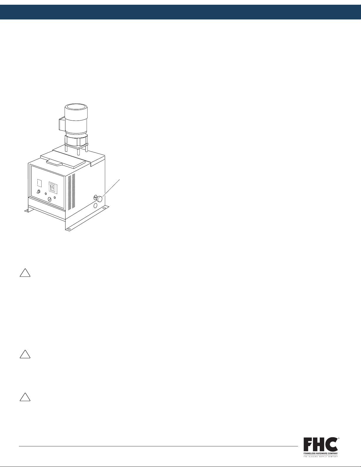
2.1 Description
The 96 Hot Melt Unit is a hot melt applicator system developed to melt and pump high viscosity butyl rubber-based
sealant. The melt unit features a 10 lb (4.5 kg) capacity tank. The cylindrical design accepts briquette form butyl sealants,
which are converted to fluid state and pumped by an electric motor-driven gear pump through an L2 Handgun/hose as-
sembly.
A rotating chain and scraper assembly in the tank propels the molten butyl sealant to the pump inlet port. A 38/31 rpm
60/50 Hz 1/6 hp motor and flow control valve provide output control. Tank temperature is regulated by an adjustable bime-
tallic controller mounted directly on the melt unit base. Hose temperature is controlled by an adjustable thermostat with
capillary bulb sensor.
The 96 Hot Melt Unit features the proven all-electric heating and pumping system. The melt unit is housed in an indus-
trial grade sheet metal enclosure and comes with a standard 8 ft (2.44 m) handgun/hose assembly; a 12 ft (3.66 m) hose
assembly is optional.
2.2 Features
ɸ All-electric systems available for 115 VAC power
ɸ Pumps high viscosity materials up to 500,000 centipoise
ɸ No compressed air
ɸ Positive-displacement V1-675 gear pump
ɸ A pump warm-up thermostat protects the pump drive mechanism by preventing operation below a safe temperature level
ɸ Tank and hose/handgun temperatures independently controlled
ɸ Over temperature protection if tank thermostat fails
ɸ Pump output adjusts by turning external flow control knob
ɸ Switched handgun assembly decreases pump wear and increases motor service life
SS96 Hot Melt Unit 19600-135 Rev. B 10/26/00 3
2 Introduction
2.1 Description The SS96 Hot Melt Unit is a hot melt applicator system developed
to melt and pump high viscosity butyl rubber-based sealant. The
melt unit features a 10 lb (4.5 kg) capacity tank. The cylindrical
design accepts briquette form butyl sealants, which are converted
to fluid state and pumped by an electric motor-driven gear pump
through an L2 Handgun/hose assembly.
A rotating chain and scraper assembly in the tank propels the
molten butyl sealant to the pump inlet port. A 38/31 rpm 60/50 Hz
1/6 hp motor and flow control valve provide output control.
Tank temperature is regulated by an adjustable bimetallic
controller mounted directly on the melt unit base. Hose
temperature is controlled by an adjustable thermostat with
capillary bulb sensor.
The SS96 Hot Melt Unit features the proven all-electric heating
and pumping system. The melt unit is housed in an industrial-
grade sheet metal enclosure and comes with a standard 8 ft
(2.44 m) handgun/hose assembly; a 12 ft (3.66 m) hose assembly
is optional.
2000354
FHC96
FHC96
FHC PRODUCT MANUAL Item No. FHC96
FRAMELESS HARDWARE COMPANYLLC| 4361 Firestone Blvd. Los Angeles, CA 90033| Toll Free: (888) 295-4531Fax: (323) 336-8307| fhc-usa.com
LIT0251 12.01.22
PAGE 7 OF 31
EXPERIENCE AND INNOVATION

GLASS DRILL INSTRUCTION MANUAL
P. 8
3 SPECIFICATIONS
3.1 Electrical
Input voltage .............................................................................. 115 VAC single phase
Power requirement ................................................................. Melt unit 900 W
............................................................................................................ Hose, 8 ft 262 W
............................................................................................................ Hose, 12 ft 390 W
............................................................................................................ Handgun 120 W
Breaker rating............................................................................. 15 A
3.2 Physical
Tank capacity ............................................................................. 4.5 kg (10 lb)
Hose capacity ............................................................................ 1 no. 8 hose
Shipping weight ........................................................................ 29.1 kg (64 lb)
3.3 Performance
Warm up time ............................................................................. 45–60 minutes
Melt rate ........................................................................................ 3.6 kg/hr (8 lb/hr)
Viscosity ........................................................................................ Maximum 500,000 cps
Temperature range:
Melt tank ................................................................................ 37–232 °C (100–450 °F)
Hose ........................................................................................ 175–232 °C (350–450 °F)
Maximum pump flow rate:
Motor rpm ............................................................................ 38/31 rpm @ 60/50 Hz
Pump size ............................................................................. V1-675
Output .................................................................................... 18.1 kg/hr (40 lb/hr)
3.4 Environmental
Storage temperature ............................................................. 0–60 °C (32–140 °F)
Ambient air temperature ..................................................... 5–45 °C (41–113 °F)
Humidity ....................................................................................... 30–95 R.H. (%)
FHC PRODUCT MANUAL Item No. FHC96
FRAMELESS HARDWARE COMPANYLLC| 4361 Firestone Blvd. Los Angeles, CA 90033| Toll Free: (888) 295-4531Fax: (323) 336-8307| fhc-usa.com
LIT0251 12.01.22
PAGE 8 OF 31
EXPERIENCE AND INNOVATION

P. 9
3 SPECIFICATIONS (CONT.)
3.5 Dimension
4 INSTALLATION
4.1 Setup
1. Remove all packaging material around melt unit.
2. Carefully lift melt unit out of box.
3. Unpack binder containing manuals and warranty information. Retain for future reference.
4. Unscrew four screws from plywood board base.
5. Carefully uncoil hose from around melt unit and remove bubble wrap from handgun.
6. Position melt unit for convenient servicing and easy access to control panel.
7. Use level mounting surface to prevent warping of melt unit and misalignment of pump and motor shaft.
8. Using the base mounting holes, bolt melt unit to a durable mounting surface in accordance with illustration on
opposite page to prevent accidental upset and possible injury.
9. Assure all screws are tight before startup. If melt unit experiences excessive vibration, re-tighten screws.
4.2 Component Installation
1. Manual systems are generally shipped with all standard components installed. No user installation is required.
2. In the event a melt unit is received without an attached handgun/hose assembly, refer to Section 8.1, Hose Replacement.
6SS96 Hot Melt Unit 19600-135 Rev. B 10/26/00
3.5 Dimensions
269.875mm
10.625 in.
355.60mm
14.0 in.
558.80mm
22.0 in.
285.75mm
11.25 in.
292.10mm
11.50 in.
342.90mm
13.50 in.
2000355
FHC PRODUCT MANUAL Item No. FHC96
FRAMELESS HARDWARE COMPANYLLC| 4361 Firestone Blvd. Los Angeles, CA 90033| Toll Free: (888) 295-4531Fax: (323) 336-8307| fhc-usa.com
LIT0251 12.01.22
PAGE 9 OF 31
EXPERIENCE AND INNOVATION

P. 10
GLASS DRILL INSTRUCTION MANUAL
GLASS DRILL INSTRUCTION MANUAL
4 INSTALLATION (CONT.)
4.3 Electrical Circuits and Wiring
96 Melt Units use single phase 115 VAC power sources with earth ground for safety. See illustration below for terminal
block location. An identification plate is attached to each melt unit on the outside rear door of the tank housing. This plate
specifies the exact melt unit voltage and pump motor frequency. Pump motor voltage, frequency and current are specified
on the motor data plate. For safe and proper installation, refer to the identification plate before applying electrical power to
melt unit.
4.3.1 Power Cord
Prewired 115 VAC ų6 Melt Units are equipped with a power cord and a standard 3-prong grounding power plug. The
system becomes fully operable by plugging the power cord into a grounded outlet.
4.3.2 Switched Handgun Pump Motor Circuit
The switched pump motor circuit allows the pump motor to be switched ON and OFF using the handgun trigger. This feature
increases pump motor life and turns ON the pump motor at the time of application. This remote switch is located on switched
handguns and is wired into the melt unit between terminal block locations TA-9 and TA-9a.
8SS96 Hot Melt Unit 19600-135 Rev. B 10/26/00
CAUTION: To avoid possible system damage,
always check wiring configuration in terminal
blocks to verify the jumpers are in their correct
locations.
4.3 Electrical Circuits and Wiring
SS96 Melt Units use single phase 115 VAC power sources with
earth ground for safety. See illustration below for terminal block
location. An identification plate is attached to each melt unit on the
outside rear door of the tank housing. This plate specifies the
exact melt unit voltage and pump motor frequency. Pump motor
voltage, frequency and current are specified on the motor data
plate. For safe and proper installation, refer to the identification
plate before applying electrical power to melt unit.
Block Diagram 115 VAC Single Phase:
4.3.1 Power Cord
Prewired 115 VAC SS96 Melt Units are equipped with a power
cord and a standard 3-prong grounding power plug. The system
becomes fully operable by plugging the power cord into a
grounded outlet.
4.3.2 Switched Handgun Pump Motor Circuit
The switched pump motor circuit allows the pump motor to be
switched ON and OFF using the handgun trigger. This feature
increases pump motor life and turns ON the pump motor at the
time of application. This remote switch is located on switched
handguns and is wired into the melt unit between terminal block
locations TA-9 and TA-9a.
!
L2G
NL1
2000356
115
115
GroundNeutralL1
2000357
FHC96
FHC96
FHC PRODUCT MANUAL Item No. FHC96
FRAMELESS HARDWARE COMPANYLLC| 4361 Firestone Blvd. Los Angeles, CA 90033| Toll Free: (888) 295-4531Fax: (323) 336-8307| fhc-usa.com
LIT0251 12.01.22
PAGE 10 OF 31
EXPERIENCE AND INNOVATION

GLASS DRILL INSTRUCTION MANUAL
P. 11
5 OPERATION
5.1 Controls and Indicators
Read this section carefully before attempting to operate this machine. See illustration on opposite page.
[1] System Power Switch/Circuit Breaker and Indicator
A magnetic type breaker opens the circuit at currents exceeding 15 A. The power switch illuminates when in the ON position.
[2] Pump On/Off Breaker Switch
Allows user to switch OFF pump motor during system warm up or maintenance. It is a magnetic type circuit breaker that
protects the motor during overload conditions.
[3] Tank Thermometer
Indicates temperature of the material in the melt tank.
[4] Tank Heating Indicator
Illuminates amber when tank heaters are powered and assists the user when making temperature adjustments to the tank
temperature controller.
[5] Tank Over temperature Indicator
Indicates tank temperatures exceeding approximately 232 °C (450 °F). In the event of a tank thermostat failure, power to
the tank heaters is controlled by a back-up thermostat and light illuminates red indicating an over temperature condition.
Should an over temperature condition occur, turn tank temperature control down or replace if failed. Refer to Section 7,
Troubleshooting.
[6] Applicator
Not applicable to this unit.
[7] Flow Control Valve (not shown)
Controls the amount of adhesive available at the applicator by a pump pressure bypass valve, or flow control valve attached
to the gear pump. Adjust on the right side of the melt unit. Refer to Adhesive Flow Adjustment Section 5.3.3.
[8] Tank Temperature Controller (not shown)
A full-range adjustable thermostat sets and controls tank temperature. Located on the front of the melt tank base, it is
accessible at the small access panel inside the electrical enclosure. Adjustment requires a flat blade screwdriver. Refer to
Tank Temperature Controller, Section 5.3.1.
[9] Hose Temperature Controller (not shown)
An adjustable thermostat controller sets and controls hose temperature. Located on the thermal panel inside the electrical
enclosure, the controller is attached to a capillary bulb sensor located in the hose. Refer to Hose Temperature Controller,
Section 5.3.2.
SS96 Hot Melt Unit 19600-135 Rev. B 10/26/00 11
[8] Tank Temperature Controller (not shown)
A full-range adjustable thermostat sets and controls tank
temperature. Located on the front of the melt tank base, it is
accessible at the small access panel inside the electrical
enclosure. Adjustment requires a flat blade screwdriver. Refer to
Tank Temperature Controller, Section 5.3.1.
[9] Hose Temperature Controller (not shown)
An adjustable thermostat controller sets and controls hose
temperature. Located on the thermal panel inside the electrical
enclosure, the controller is attached to a capillary bulb sensor
located in the hose. Refer to Hose Temperature Controller,
Section 5.3.2.
ON
OFF
PUMP
HEATING OVERTEMP
POWER
APPLICATOR
TEMPERATURE
TANK
ON
OFF
1
5
34
2
6
2000345
FHC PRODUCT MANUAL Item No. FHC96
FRAMELESS HARDWARE COMPANYLLC| 4361 Firestone Blvd. Los Angeles, CA 90033| Toll Free: (888) 295-4531Fax: (323) 336-8307| fhc-usa.com
LIT0251 12.01.22
PAGE 11 OF 31
EXPERIENCE AND INNOVATION

GLASS DRILL INSTRUCTION MANUAL
P. 12
5 OPERATION (CONT.)
5.2 Startup Instructions
DANGER: To avoid personal injury, follow all safety labels. Failure to properly operate and maintain equipment can lead
to serious injury.
Ŀ Wear protective clothing, safety goggles and safety gloves. Hot melt materials can cause severe burns resulting in dis-
figurement or blindness.
Ŀ Use only manufacturer recommended materials in this system. Fire, explosion, personal injury, property and equipment
damage can result if improper or unsafe materials are used.
Ŀ Disconnect electrical power from external source to melt unit before undertaking maintenance or troubleshooting.
Failure to disconnect power can result in fatal electrical shock.
Ŀ Depressurize system before performing any maintenance to pump, pump filter, flow control valve or hose. Turn pump
switch off and depress trigger on handgun until there is no flow. Air trapped in the system or in a component can form a
pressure pocket. Loosen fittings cautiously. Adhesive under pressure can cause severe burns and blindness.
Ŀ Always read the manufacturer’s recommended use of the material.
1. Become familiar with Section 5.1, Controls and Indicators.
2. Install melt unit as specified in Section 4, Installation.
3. Fill tank with hot melt material.
4. Turn melt unit on and allow sufficient warm up time for hot melt material to thoroughly melt.
5. Align motor on receipt of a new unit or after transportation.
a. Loosen four screws holding motor pan to side of melt unit.
b. Heat melt unit and run motor. This centers the motor.
c. With motor running, tighten four screws in a crisscross pattern.
6. Set hose and tank temperatures to desired settings. Lower settings increase pot life of the material. Materials degrade
over time due to oxidation.
7. To prevent motor stalling, adjust flow control valve to the minimum flow requirement.
5.3 Adjustments
5.3.1 Tank Temperature Controller
1. To prevent hot melt degradation, set melt tank temperature to the minimum temperature specified by hot melt manu-
facturer.
2. Open front control panel.
3. To raise melt tank temperature, turn tank temperature controller adjustment shaft [1] clockwise with screwdriver. See
illustration below.
4. To lower melt tank temperature, turn adjustment shaft [1] counter-clockwise with screwdriver. The melt tank
temperature controller range is 260 °C (500 °F) for one 320° rotation of the adjustment shaft.
5. Allow melt tank temperature to stabilize 30 minutes before adjusting further.
6. Verify temperature on tank thermometer.
12 SS96 Hot Melt Unit 19600-135 Rev. B 10/26/00
DANGER: To avoid personal injury, follow all
safety labels. Failure to properly operate and
maintain equipment can lead to serious injury.
•Wear protective clothing, safety goggles and
safety gloves. Hot melt materials can cause
severe burns resulting in disfigurement or
blindness.
•Use only manufacturer recommended materials
in this system. Fire, explosion, personal injury,
property and equipment damage can result if
improper or unsafe materials are used.
•Disconnect electrical power from external
source to melt unit before undertaking
maintenance or troubleshooting. Failure to
disconnect power can result in fatal electrical
shock.
•Depressurize system before performing any
maintenance to pump, pump filter, flow control
valve or hose. Turn pump switch off and
depress trigger on handgun until there is no
flow. Air trapped in the system or in a
component can form a pressure pocket.
Loosen fittings cautiously. Adhesive under
pressure can cause severe burns and
blindness.
•Always read the manufacturer’s recommended
use of the material.
5.2 Startup Instructions
1. Become familiar with Section 5.1, Controls and Indicators.
2. Install melt unit as specified in Section 4, Installation.
3. Fill tank with hot melt material.
4. Turn melt unit on and allow sufficient warmup time for hot
melt material to thoroughly melt.
5. Align motor on receipt of a new unit or after transportation.
a. Loosen four screws holding motor pan to side of melt
unit.
b. Heat melt unit and run motor. This centers the motor.
c. With motor running, tighten four screws in a crisscross
pattern.
6. Set hose and tank temperatures to desired settings. Lower
settings increase pot life of the material. Materials degrade
over time due to oxidation.
7. To prevent motor stalling, adjust flow control valve to the
minimum flow requirement.
!
FHC PRODUCT MANUAL Item No. FHC96
FRAMELESS HARDWARE COMPANYLLC| 4361 Firestone Blvd. Los Angeles, CA 90033| Toll Free: (888) 295-4531Fax: (323) 336-8307| fhc-usa.com
LIT0251 12.01.22
PAGE 12 OF 31
EXPERIENCE AND INNOVATION

GLASS DRILL INSTRUCTION MANUAL
P. 13
5 OPERATION (CONT.)
5.3.2 Hose Temperature Controller
Temperature graduations on hose controller reflect approximate hose temperature.
1. Measure inside hose temperature with a pyrometer and bead probe. Hose temperature should be the minimum
temperature required for application to prevent degradation of material in the hose and maximize hose life.
2. Open front control panel.
3. To raise hose temperature, turn adjustment shaft [2] clockwise with screwdriver to desired temperature on dial.
See illustration below.
4. To lower hose temperature, turn adjustment shaft [2] counterclockwise with screwdriver to desired temperature on dial.
5. Refer to Temperature Check in Maintenance section of the handgun manual.
5.3.3 Adhesive Flow Adjustment
CAUTION: For maximum performance and motor life, do not allow pump motor to stall. A prolonged stall condition
will cause motor to go into thermal overload.
Flow Control Valve
An adjustable pressure regulating device is mounted on the pump under the melt unit chassis.
1. Adjust adhesive flow with flow control knob [1] on right side of melt unit.
2. To increase pressure and adhesive flow, turn knob [1] clockwise.
3. To decrease pressure and adhesive flow, turn knob [1] counterclockwise.
4. To achieve minimum pressure and lowest flow rate suitable for application, turn knob fully counterclockwise. Gradually
turn clockwise until desired pressure and flow rate is reached.
SS96 Hot Melt Unit 19600-135 Rev. B 10/26/00 13
5.3 Adjustments
5.3.1 Tank Temperature Controller
1. To prevent hot melt degradation, set melt tank temperature to
the minimum temperature specified by hot melt manufacturer.
2. Open front control panel.
3. To raise melt tank temperature, turn tank temperature
controller adjustment shaft [1] clockwise with screwdriver. See
illustration below.
4. To lower melt tank temperature, turn adjustment shaft [1]
counter-clockwise with screwdriver. The melt tank
temperature controller range is 260 °C (500 °F) for one 320°
rotation of the adjustment shaft.
5. Allow melt tank temperature to stabilize 30 minutes before
adjusting further.
6. Verify temperature on tank thermometer.
5.3.2 Hose Temperature Controller
Temperature graduations on hose controller reflect approximate
hose temperature.
1. Measure inside hose temperature with a pyrometer and bead
probe. Hose temperature should be the minimum temperature
required for application to prevent degradation of material in
the hose and maximize hose life.
2. Open front control panel.
3. To raise hose temperature, turn adjustment shaft [2]
clockwise with screwdriver to desired temperature on dial.
See illustration below.
4. To lower hose temperature, turn adjustment shaft [2]
counterclockwise with screwdriver to desired temperature on
dial.
5. Refer to Temperature Check in Maintenance section of the
handgun manual.
12000008a
2
12 SS96 Hot Melt Unit 19600-135 Rev. B 10/26/00
DANGER: To avoid personal injury, follow all
safety labels. Failure to properly operate and
maintain equipment can lead to serious injury.
•Wear protective clothing, safety goggles and
safety gloves. Hot melt materials can cause
severe burns resulting in disfigurement or
blindness.
•Use only manufacturer recommended materials
in this system. Fire, explosion, personal injury,
property and equipment damage can result if
improper or unsafe materials are used.
•Disconnect electrical power from external
source to melt unit before undertaking
maintenance or troubleshooting. Failure to
disconnect power can result in fatal electrical
shock.
•Depressurize system before performing any
maintenance to pump, pump filter, flow control
valve or hose. Turn pump switch off and
depress trigger on handgun until there is no
flow. Air trapped in the system or in a
component can form a pressure pocket.
Loosen fittings cautiously. Adhesive under
pressure can cause severe burns and
blindness.
•Always read the manufacturer’s recommended
use of the material.
5.2 Startup Instructions
1. Become familiar with Section 5.1, Controls and Indicators.
2. Install melt unit as specified in Section 4, Installation.
3. Fill tank with hot melt material.
4. Turn melt unit on and allow sufficient warmup time for hot
melt material to thoroughly melt.
5. Align motor on receipt of a new unit or after transportation.
a. Loosen four screws holding motor pan to side of melt
unit.
b. Heat melt unit and run motor. This centers the motor.
c. With motor running, tighten four screws in a crisscross
pattern.
6. Set hose and tank temperatures to desired settings. Lower
settings increase pot life of the material. Materials degrade
over time due to oxidation.
7. To prevent motor stalling, adjust flow control valve to the
minimum flow requirement.
!
FHC PRODUCT MANUAL Item No. FHC96
FRAMELESS HARDWARE COMPANYLLC| 4361 Firestone Blvd. Los Angeles, CA 90033| Toll Free: (888) 295-4531Fax: (323) 336-8307| fhc-usa.com
LIT0251 12.01.22
PAGE 13 OF 31
EXPERIENCE AND INNOVATION
P. 14
5 OPERATION (CONT.)
Flow Control Valve (Image)
6 MAINTENANCE
WARNING: Hot Melt materials can cause severe burns resulting in disfigurement or blindness. Follow these
precautions before beginning any maintenance:
Ŀ Wear protective clothing, safety goggles, and safety gloves.
Ŀ Turn pump motor switch to off position. De-pressurize applicator(s) by triggering.
Ŀ Unless stated otherwise, always allow melt unit to cool before beginning any maintenance.
Ŀ Disconnect hose electrical connector when hose fittings are disconnected and power is off.
CAUTION: To prevent damage to components (hose fittings, etc.), heat part(s) being serviced to approximately 121 °C
(250°F) prior to dismantling, assembling, or adjusting. Heat parts by applying power to the unit using a hand held hot
air gun or placing parts on a hot plate. Failure to do this will result in stripped threads and ruining both parts and tools.
CAUTION: To avoid arcing of electrical contacts and possible failure of components, do not connect electrical
connectors when the hose power switch is on.
14 SS96 Hot Melt Unit 19600-135 Rev. B 10/26/00
CAUTION: For maximum performance and motor
life, do not allow pump motor to stall. A prolonged
stall condition will cause motor to go into thermal
overload.
5.3.3 Adhesive Flow Adjustment
Flow Control Valve
An adjustable pressure regulating device is mounted on the pump
under the melt unit chassis.
1. Adjust adhesive flow with flow control knob [1] on right side of
melt unit.
2. To increase pressure and adhesive flow, turn knob [1]
clockwise.
3. To decrease pressure and adhesive flow, turn knob [1]
counterclockwise.
4. To achieve minimum pressure and lowest flow rate suitable
for application, turn knob fully counterclockwise. Gradually
turn clockwise until desired pressure and flow rate is reached.
!
1
2000359
12 SS96 Hot Melt Unit 19600-135 Rev. B 10/26/00
DANGER: To avoid personal injury, follow all
safety labels. Failure to properly operate and
maintain equipment can lead to serious injury.
•Wear protective clothing, safety goggles and
safety gloves. Hot melt materials can cause
severe burns resulting in disfigurement or
blindness.
•Use only manufacturer recommended materials
in this system. Fire, explosion, personal injury,
property and equipment damage can result if
improper or unsafe materials are used.
•Disconnect electrical power from external
source to melt unit before undertaking
maintenance or troubleshooting. Failure to
disconnect power can result in fatal electrical
shock.
•Depressurize system before performing any
maintenance to pump, pump filter, flow control
valve or hose. Turn pump switch off and
depress trigger on handgun until there is no
flow. Air trapped in the system or in a
component can form a pressure pocket.
Loosen fittings cautiously. Adhesive under
pressure can cause severe burns and
blindness.
•Always read the manufacturer’s recommended
use of the material.
5.2 Startup Instructions
1. Become familiar with Section 5.1, Controls and Indicators.
2. Install melt unit as specified in Section 4, Installation.
3. Fill tank with hot melt material.
4. Turn melt unit on and allow sufficient warmup time for hot
melt material to thoroughly melt.
5. Align motor on receipt of a new unit or after transportation.
a. Loosen four screws holding motor pan to side of melt
unit.
b. Heat melt unit and run motor. This centers the motor.
c. With motor running, tighten four screws in a crisscross
pattern.
6. Set hose and tank temperatures to desired settings. Lower
settings increase pot life of the material. Materials degrade
over time due to oxidation.
7. To prevent motor stalling, adjust flow control valve to the
minimum flow requirement.
!
FHC PRODUCT MANUAL Item No. FHC96
FRAMELESS HARDWARE COMPANYLLC| 4361 Firestone Blvd. Los Angeles, CA 90033| Toll Free: (888) 295-4531Fax: (323) 336-8307| fhc-usa.com
LIT0251 12.01.22
PAGE 14 OF 31
EXPERIENCE AND INNOVATION

GLASS DRILL INSTRUCTION MANUAL
P. 15
6 MAINTENANCE (CONT.)
6.1 Preventive Maintenance
6.1.1 Monthly Inspection Procedure
1. Verify hose is properly supported so it is not over stressed during use. Minimum bend radius is 20.32 cm (8 in.)
when hot.
2. Check tank and hose temperatures and adjust as explained in Sections 5.3.1 and 5.3.2.
* Extra maintenance required for continuous duty machines.
7 TROUBLESHOOTING
Procedure Daily Monthly As Required*
Check for foreign material in tank. X
Wipe off excess sealant from cover. X X X
Purge tank and hoses. X X
Clean applicator nozzle. X X
Check for leaks. X
Problem Solutions
Tank does not heat
1. Turn on main power breaker switch. If switch light fails to illuminate, replace switch.
2. Inspect power-in connections for proper fit.
3. Check for faulty wires.
4. Inspect power wires or power plug at main power source.
5. Check supply voltage to melt unit with voltmeter.
6. Check incoming control voltage to terminal blocks.
7. Check tank controller for proper operation.
8. Compare wire connections to electrical schematic to ensure melt unit is properly wired.
9. If problem persists, check tank heaters as specified under Section 8.6, Tank Heater Replacement.
10. Check incoming power to ensure voltage matches rating of melt unit.
Tank heats slowly
1. Check status of components with a voltmeter (system powered) or ohmmeter
(system un-powered, wires disconnected).
2. Adjust tank temperature controller.
3. If problem persists, check tank heaters as specified under Section 8.6, Tank Heater Replacement.
Tank over
temperature
indicator light on.
1. Check tank temperature when over-temp indicator is lit. If too high, turn tank controller coun-
terclockwise to reduce temperature. If light is on at an acceptable or low tank temperature,
thermostat is faulty or rated at a low temperature. Replace over temperature thermostat.
Handgun and
hose heat slowly.
1. Adjust hose and handgun temperature controllers.
2. Check voltage to hose controller.
3. Verify hose electrical connector is properly connected. If problem persists, refer to Section
8.2, Hose Controller Replacement.
4. Verify proper temperature range of hose controller.
FHC PRODUCT MANUAL Item No. FHC96
FRAMELESS HARDWARE COMPANYLLC| 4361 Firestone Blvd. Los Angeles, CA 90033| Toll Free: (888) 295-4531Fax: (323) 336-8307| fhc-usa.com
LIT0251 12.01.22
PAGE 15 OF 31
EXPERIENCE AND INNOVATION

GLASS DRILL INSTRUCTION MANUAL
P. 16
7 TROUBLESHOOTING (CONT.)
If troubleshooting attempts fail, contact your factory representative.
Problem Solutions
Handgun and hose
fail to heat.
1. Verify incoming hose power connector is properly installed. Connector wire pins may be
misaligned or loose.
2. If no change, disconnect incoming hose power connector and check hose heater resistance
with ohmmeter. If hose heater has failed, replace hose. Refer to Heated Hose Manual.
3. Determine if applicator is heating by using a pyrometer or temperature sensing device. Do
not touch applicator by hand to determine temperature. Refer to handgun manual.
Adhesive output
too high
1. Decrease system fluid pressure with flow control valve. If no change, remove nozzle and
replace with a smaller orifice nozzle.
2. Decrease hose temperature by 4–10 °C (25–50 °F). If no change, consult your hot melt
material vendor regarding application.
3. Decrease tank temperature by 4 °C (25 °F).
Adhesive output
too low
1. Increase system fluid pressure without stalling motor by adjusting flow control valve.
If no change, remove nozzle and replace with a larger orifice nozzle.
2. Clean applicator nozzle.
3. Purge system.
4. Hot melt formulations tend to be a factor in previously listed problems. Refer to
Section 5.2, Startup Instructions, for cautions.
5. Increase hose temperature by 4–10 °C (25–50 °F). If no change, consult your hot melt
material vendor regarding application.
FHC PRODUCT MANUAL Item No. FHC96
FRAMELESS HARDWARE COMPANYLLC| 4361 Firestone Blvd. Los Angeles, CA 90033| Toll Free: (888) 295-4531Fax: (323) 336-8307| fhc-usa.com
LIT0251 12.01.22
PAGE 16 OF 31
EXPERIENCE AND INNOVATION

GLASS DRILL INSTRUCTION MANUAL
P. 17
8 REPAIR AND REPLACEMENT
Refer to Parts List, in Section 9, for all replacement parts listed in this section.
8.1 Hose Replacement
8.1.1 REMOVAL OF EXISTING HOSE
1. Turn off system power and allow hot melt in tank to completely solidify.
2. Turn system back on for 5 minutes to allow fittings to warm up or heat fitting with a hand-held hot air gun.
3. Turn off system power and disconnect melt unit electrical power.
4. Disconnect hose electrical connector [1].
5. Remove screws [2] from hose mounting block [3]. See illustration below.
6. Tilt unit backward.
7. Loosen hose JIC fitting [4] and remove hose from fitting [5] on flow control block [6].
8. Carefully remove capillary bulb [7] from hose.
CAUTION:
For safe and proper hose replacement, verify all material in the melt tank has completely solidified.
12 SS96 Hot Melt Unit 19600-135 Rev. B 10/26/00
DANGER: To avoid personal injury, follow all
safety labels. Failure to properly operate and
maintain equipment can lead to serious injury.
•Wear protective clothing, safety goggles and
safety gloves. Hot melt materials can cause
severe burns resulting in disfigurement or
blindness.
•Use only manufacturer recommended materials
in this system. Fire, explosion, personal injury,
property and equipment damage can result if
improper or unsafe materials are used.
•Disconnect electrical power from external
source to melt unit before undertaking
maintenance or troubleshooting. Failure to
disconnect power can result in fatal electrical
shock.
•Depressurize system before performing any
maintenance to pump, pump filter, flow control
valve or hose. Turn pump switch off and
depress trigger on handgun until there is no
flow. Air trapped in the system or in a
component can form a pressure pocket.
Loosen fittings cautiously. Adhesive under
pressure can cause severe burns and
blindness.
•Always read the manufacturer’s recommended
use of the material.
5.2 Startup Instructions
1. Become familiar with Section 5.1, Controls and Indicators.
2. Install melt unit as specified in Section 4, Installation.
3. Fill tank with hot melt material.
4. Turn melt unit on and allow sufficient warmup time for hot
melt material to thoroughly melt.
5. Align motor on receipt of a new unit or after transportation.
a. Loosen four screws holding motor pan to side of melt
unit.
b. Heat melt unit and run motor. This centers the motor.
c. With motor running, tighten four screws in a crisscross
pattern.
6. Set hose and tank temperatures to desired settings. Lower
settings increase pot life of the material. Materials degrade
over time due to oxidation.
7. To prevent motor stalling, adjust flow control valve to the
minimum flow requirement.
!
SS96 Hot Melt Unit 19600-135 Rev. B 10/26/00 19
CAUTION: For safe and proper hose replacement,
verify all material in the melt tank has completely
solidified.
8 Repair and Replacement
Refer to Parts List, in Section 9, for all replacement parts listed in
this section.
8.1 Hose Replacement
8.1.1 Removal of Existing Hose
1. Turn off system power and allow hot melt in tank to completely
solidify.
2. Turn system back on for 5 minutes to allow fittings to warm up
or heat fitting with a hand-held hot air gun.
3. Turn off system power and disconnect melt unit electrical
power.
4. Disconnect hose electrical connector [1].
5. Remove screws [2] from hose mounting block [3]. See
illustration below.
6. Tilt unit backward.
7. Loosen hose JIC fitting [4] and remove hose from fitting [5] on
flow control block [6].
8. Carefully remove capillary bulb [7] from hose.
!
7
6
5
231
4
ON
OFF
PUMP
OVERTEMP
POWER
APPLICATOR
TEMPERATURE
ON
OFF
2000348
FHC PRODUCT MANUAL Item No. FHC96
FRAMELESS HARDWARE COMPANYLLC| 4361 Firestone Blvd. Los Angeles, CA 90033| Toll Free: (888) 295-4531Fax: (323) 336-8307| fhc-usa.com
LIT0251 12.01.22
PAGE 17 OF 31
EXPERIENCE AND INNOVATION

GLASS DRILL INSTRUCTION MANUAL
P. 18
8 REPAIR AND REPLACEMENT (CONT.)
8.1.2 Installation of New Hose
1. Turn off system power and disconnect melt unit electrical power from external source.
2. Never flex a hose when cold. Hoses have a minimum bend radius of 20.32 cm (8 in.) when hot.
Further flexing will cause permanent damage.
3. Heat hose JIC fittings [5] before adjusting or damage may result. New or clean hose fittings may
not require heating.
4. Install hoses on melt unit by tilting melt unit back until underside is accessible. Support unit with block on back of
housing so hot melt does not spill. Do not turn melt unit upside down.
5. Support hose to prevent excessive flexing. Do not support hose in a way which may add to its thermal
insulating characteristics or overheating will result. Failure to properly support the hose will result in
premature failure.
6. Hose installation. See illustration below.
a. Carefully insert capillary bulb [4] into brass tube in end of hose [1] and do not bend capillary tube at a sharp angle.
Thermostat hoses perform best when capillary bulb is positioned at 3 or 9 o’clock. Before final tightening, rotate
hose on JIC fitting to obtain recommended position.
b. Loosely connect the hose JIC swivel fitting [5] to a straight or right angle fitting [6] on the flow control block [7].
c. Fasten hose support block [3] to chassis.
d. Attach hose electrical connector [2].
e. Tuck capillary tubing [4] and electrical connector [2] under melt unit.
f. Position and support hose before using.
g. Tighten JIC swivel fittings [5].
h. Check all hydraulic fittings for tightness before pressurizing system and re-tighten when hot. Check all
electrical connections for continuity.
i. Re-tighten hydraulic fitting after unit has reached operating temperature.
20 SS96 Hot Melt Unit 19600-135 Rev. B 10/26/00
8.1.2 Installation of New Hose
1. Turn off system power and disconnect melt unit electrical
power from external source.
2. Never flex a hose when cold. Hoses have a minimum bend
radius of 20.32 cm (8 in.) when hot. Further flexing will cause
permanent damage.
3. Heat hose JIC fittings [5] before adjusting or damage may
result. New or clean hose fittings may not require heating.
4. Install hoses on melt unit by tilting melt unit back until
underside is accessible. Support unit with block on back of
housing so hot melt does not spill. Do not turn melt unit
upside down.
5. Support hose to prevent excessive flexing. Do not support
hose in a way which may add to its thermal insulating
characteristics or overheating will result. Failure to properly
support the hose will result in premature failure.
6. Hose installation. See illustration below.
a. Carefully insert capillary bulb [4] into brass tube in end of
hose [1] and do not bend capillary tube at a sharp angle.
Thermostat hoses perform best when capillary bulb is
positioned at 3 or 9 o’clock. Before final tightening, rotate
hose on JIC fitting to obtain recommended position.
b. Loosely connect the hose JIC swivel fitting [5] to a
straight or right angle fitting [6] on the flow control
block [7].
c. Fasten hose support block [3] to chassis.
d. Attach hose electrical connector [2].
e. Tuck capillary tubing [4] and electrical connector [2]
under melt unit.
f. Position and support hose before using.
g. Tighten JIC swivel fittings [5].
h. Check all hydraulic fittings for tightness before
pressurizing system and retighten when hot. Check all
electrical connections for continuity.
i. Retighten hydraulic fitting after unit has reached
operating temperature.
4
6
7
52
3
1
2000360
FHC PRODUCT MANUAL Item No. FHC96
FRAMELESS HARDWARE COMPANYLLC| 4361 Firestone Blvd. Los Angeles, CA 90033| Toll Free: (888) 295-4531Fax: (323) 336-8307| fhc-usa.com
LIT0251 12.01.22
PAGE 18 OF 31
EXPERIENCE AND INNOVATION

GLASS DRILL INSTRUCTION MANUAL
P. 19
8 REPAIR AND REPLACEMENT (CONT.)
8.2 Hose Controller Replacement
1. Turn system power OFF and allow sealant in tank to completely solidify.
2. Turn melt unit on for 5 minutes to warm fittings or heat fittings with a hand-held hot air gun.
3. Turn system power switch OFF and disconnect melt unit electrical power.
4. Remove screws from hose mounting block.
5. Tilt unit backward and disconnect hose electrical connector. Do not turn melt unit upside down.
6. Loosen hose JIC fitting.
7. Remove hose from fitting on flow control block.
8. Remove capillary sensor from hose.
9. Open front control panel, disconnect controller [1] wires and identify locations of wires.
10. Remove 2 screws fastening controller [1] to electrical mounting panel.
11. Install new controller. Insert capillary sensor into brass tube at hose end and coil capillary tube so it hangs beneath chassis.
12. Reconnect hose electrical connector.
13. Attach hose to JIC fitting as specified in illustration below.
14. Reconnect controller wires.
15. Reconnect melt unit power.
16. Turn system power switch ON.
17. Adjust controller as specified in Section 5.3.2, Hose Temperature Controller.
18. Calibrate actual inside temperature with thermostat setting using pyrometer and bead sensor.
SS96 Hot Melt Unit 19600-135 Rev. B 10/26/00 21
8.2 Hose Controller Replacement
1. Turn system power OFF and allow sealant in tank to
completely solidify.
2. Turn melt unit on for 5 minutes to warm fittings or heat fittings
with a hand-held hot air gun.
3. Turn system power switch OFF and disconnect melt unit
electrical power.
4. Remove screws from hose mounting block.
5. Tilt unit backward and disconnect hose electrical connector.
Do not turn melt unit upside down.
6. Loosen hose JIC fitting.
7. Remove hose from fitting on flow control block.
8. Remove capillary sensor from hose.
9. Open front control panel, disconnect controller [1] wires and
identify locations of wires.
10. Remove 2 screws fastening controller [1] to electrical
mounting panel.
11. Install new controller. Insert capillary sensor into brass tube at
hose end and coil capillary tube so it hangs beneath chassis.
12. Reconnect hose electrical connector.
13. Attach hose to JIC fitting as specified in illustration below.
14. Reconnect controller wires.
15. Reconnect melt unit power.
16. Turn system power switch ON.
17. Adjust controller as specified in Section 5.3.2, Hose
Temperature Controller.
18. Calibrate actual inside temperature with thermostat setting
using pyrometer and bead sensor.
1
2000009
FHC PRODUCT MANUAL Item No. FHC96
FRAMELESS HARDWARE COMPANYLLC| 4361 Firestone Blvd. Los Angeles, CA 90033| Toll Free: (888) 295-4531Fax: (323) 336-8307| fhc-usa.com
LIT0251 12.01.22
PAGE 19 OF 31
EXPERIENCE AND INNOVATION
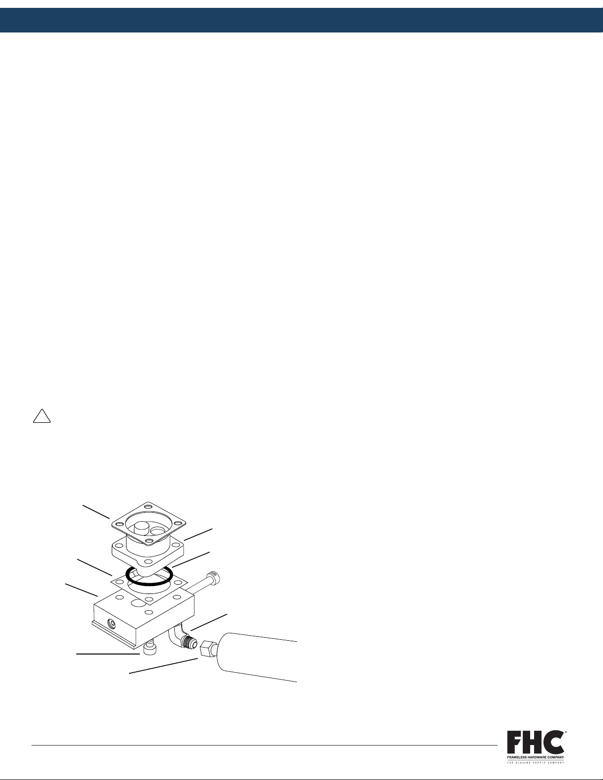
GLASS DRILL INSTRUCTION MANUAL
P. 20
8 REPAIR AND REPLACEMENT (CONT.)
8.3 Pump and Flow Control Replacement
1. If possible, pump out all adhesive in melt unit and turn system power off. If not possible, turn off system power and
allow hot melt in tank to solidify.
2. Turn on system power for 5 minutes to warm fittings.
3. Turn off system power and disconnect electrical power at external source.
4. Disconnect hose electrical connector and tilt melt unit backwards. Do not turn melt unit upside down.
5. Loosen JIC fittings [7] and remove hose from fittings [6] on flow control block [5]. See illustration below.
6. Remove 4 socket head cap screws [8] attaching flow control block [5] and pump [2] to tank. See illustration below.
7. Pull pump [2] out and remove o-ring [3], copper shim [4] and tank gasket [1]. Install new replacement seals.
8. Place o-ring [3] in pump groove after lubricating with silicon based grease.
9. Align pump [2], pump shim [4] and flow control block [5], with o-ring in place. Verify mating surfaces of pump and flow
control valve block lie flat against one another.
10. Attach flow control block [5] and pump[2], with pump gasket seated to bottom of tank using hex head cap screws and
lock washers [8].
11. Before tightening screws, check o-ring groove alignment by manually pressing flow control block [5] against pump [2].
12. Tighten all screws evenly. Torque to 8.47 N-m (75 lb-in.).
13. Reconnect hose(s) and turn melt unit power on.
CAUTION:
Verify o-ring is properly aligned in pump groove when replacing pump and/or flow control valve. A pinched or
misaligned o-ring may result in pump leakage.
12 SS96 Hot Melt Unit 19600-135 Rev. B 10/26/00
DANGER: To avoid personal injury, follow all
safety labels. Failure to properly operate and
maintain equipment can lead to serious injury.
•Wear protective clothing, safety goggles and
safety gloves. Hot melt materials can cause
severe burns resulting in disfigurement or
blindness.
•Use only manufacturer recommended materials
in this system. Fire, explosion, personal injury,
property and equipment damage can result if
improper or unsafe materials are used.
•Disconnect electrical power from external
source to melt unit before undertaking
maintenance or troubleshooting. Failure to
disconnect power can result in fatal electrical
shock.
•Depressurize system before performing any
maintenance to pump, pump filter, flow control
valve or hose. Turn pump switch off and
depress trigger on handgun until there is no
flow. Air trapped in the system or in a
component can form a pressure pocket.
Loosen fittings cautiously. Adhesive under
pressure can cause severe burns and
blindness.
•Always read the manufacturer’s recommended
use of the material.
5.2 Startup Instructions
1. Become familiar with Section 5.1, Controls and Indicators.
2. Install melt unit as specified in Section 4, Installation.
3. Fill tank with hot melt material.
4. Turn melt unit on and allow sufficient warmup time for hot
melt material to thoroughly melt.
5. Align motor on receipt of a new unit or after transportation.
a. Loosen four screws holding motor pan to side of melt
unit.
b. Heat melt unit and run motor. This centers the motor.
c. With motor running, tighten four screws in a crisscross
pattern.
6. Set hose and tank temperatures to desired settings. Lower
settings increase pot life of the material. Materials degrade
over time due to oxidation.
7. To prevent motor stalling, adjust flow control valve to the
minimum flow requirement.
!
22 SS96 Hot Melt Unit 19600-135 Rev. B 10/26/00
CAUTION: Verify o-ring is properly aligned in pump
groove when replacing pump and/or flow control
valve. A pinched or misaligned o-ring may result in
pump leakage.
8.3 Pump and Flow Control Replacement
1. If possible, pump out all adhesive in melt unit and turn system
power off. If not possible, turn off system power and allow hot
melt in tank to solidify.
2. Turn on system power for 5 minutes to warm fittings.
3. Turn off system power and disconnect electrical power at
external source.
4. Disconnect hose electrical connector and tilt melt unit
backwards. Do not turn melt unit upside down.
5. Loosen JIC fittings [7] and remove hose from fittings [6] on
flow control block [5]. See illustration below.
6. Remove 4 socket head cap screws [8] attaching flow control
block [5] and pump [2] to tank. See illustration below.
7. Pull pump [2] out and remove o-ring [3], copper shim [4] and
tank gasket [1]. Install new replacement seals.
8. Place o-ring [3] in pump groove after lubricating with silicon-
based grease.
9. Align pump [2], pump shim [4] and flow control block [5], with
o-ring in place. Verify mating surfaces of pump and flow
control valve block lie flat against one another.
10. Attach flow control block [5] and pump[2], with pump gasket
seated to bottom of tank using hex head cap screws and lock
washers [8].
11. Before tightening screws, check o-ring groove alignment by
manually pressing flow control block [5] against pump [2].
12. Tighten all screws evenly. Torque to 8.47 N-m (75 lb-in.).
13. Reconnect hose(s) and turn melt unit power on.
!
2
3
6
8
5
4
1
7
2000362
FHC PRODUCT MANUAL Item No. FHC96
FRAMELESS HARDWARE COMPANYLLC| 4361 Firestone Blvd. Los Angeles, CA 90033| Toll Free: (888) 295-4531Fax: (323) 336-8307| fhc-usa.com
LIT0251 12.01.22
PAGE 20 OF 31
EXPERIENCE AND INNOVATION
Table of contents
Popular Industrial Equipment manuals by other brands


A.B.S.
A.B.S. Flexilo MODUL Assembly-, Operating-, and Filling Instructions

ABB
ABB HT843934 Operation manual

Hydrafeed
Hydrafeed Multifeed 65 manual

SAMCHULLY
SAMCHULLY SYH instruction manual

nbs
nbs Citadel 2.0 Series Installation, operation and maintenance manual

Emerson
Emerson PACSystems RXi Series user manual