FHC Guideline 4000 LP+ Manual

L011-57 Rev. D1 2018-11-09 Page 1 of 11
Guideline 4000 LP+™
neuromodulation targeting system
Directions For Use
L011-57 (Rev D1, 2018-11-09)
Contains directions for the following products:
MT-LPP, MT-LPP-APM, 66-EL-LP
FHC, Inc.
1201 Main Street
Bowdoin, ME 04287 USA
Fax: +1-207-666-8292
www.fh-co.com
FHC Europe
(TERMOBIT PROD srl)
42A Barbu Vacarescu Str, 3rd Fl
Bucharest 020281 Sector 2
Romania
FHC Latin America
Calle 6 Sur Cra 43 A-200
Edificio LUGO Oficina 1406
Medellín-Colombia
24 hour technical service:
1-800-326-2905 (US & Can)
+1-207-666-8190
www.fh-co.com

L011-57 Rev. D1 2018-11-09 Page 2 of 11

L011-57 Rev. D1 2018-11-09 Page 3 of 11
Table of Contents:
Indications for use, Intended use, Applicable Standards
Symbol Key
Warnings and Cautions
System Maintenance and Repair
Handling Considerations
Maintenance
Repair
System Disposal
System Specifications - Performance & Accuracy
Microelectrode Recording
Stimulation
Impedance Check
Analog Inputs
Inventory
Ordering Information
System Set-up and Pre-Use Checkout
4
4
4
5
5
5
5
5
5
5
6
6
6
6
7
7
L011-57 Rev. D1 2018-11-09 Page 4 of 11
Indications for use:
The microTargeting™ Guideline 4000 LP+™ neuromodulation targeting system is intended to assist in functional
neurosurgical procedures where recording from and stimulation of brain motor and sensory neurons will aid in the
placement of depth electrodes.
Intended use:
The Guideline 4000 LP+™ neuromodulation targeting system is intended to be used by a neurosurgeon, neurologist or
clinical neurophysiologist to accurately position depth electrodes during functional neurosurgical procedures.
Applicable Standards:
General Standard: EN60601-1 General Electrical Safety; Collateral Standards: 60601-1-1, 60601-1-2, 60601-1-4, 60601-1-4, 60601-1-6;
Particular Standard: EN60601-2-26; The Guideline 4000 LP+™ is a Class 1 medical device with a type BF applied part.
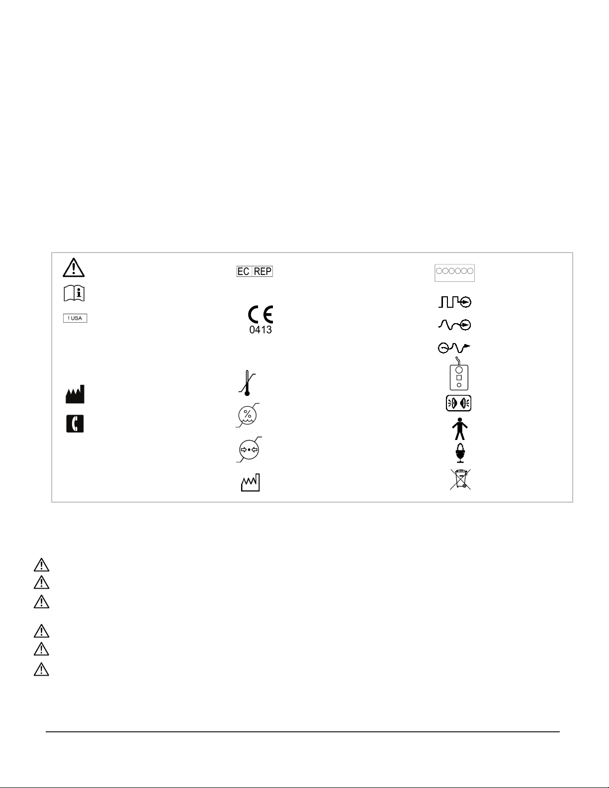
Symbol Key
WARNING / Caution, consult instructions
for important cautionary information.
Consult the instructions for use.
In reference to“Rx only” symbol; this
applies to USA audiences only
Caution- Federal law (USA) restricts
this device to sale by or on the order
of a physician.
Medical device manufacturer, as defined
in EU Directives 90/385/EEC, 93/42/EEc
and 98/79/EC.
Telephone number
Indicates the catalog number so that the
medical device can be identified.
Indicates the serial number so that a
specific medical device can be identified.
Authorized Representative in the
European Community
European Conformity. This device fully
complies with MDD Directive 93/42/EEC
and legal responsibilities as a manufacturer
are with FHC, Inc., 1201 Main Street,
Bowdoin, ME 04287 USA.
Temperature limitation: Storage conditions
are between 0°C - 40°C (32°F - 104°F)
Humidity limitation: Not to exceed 95%
Atmospheric pressure limitation:
between 500hPa and 1060hPa
Date when the medical device was
manufactured.
Rx only
Rx only
0%
95%
j
n
Warnings and Cautions:
WARNING: The Guideline 4000 LP+ does no analysis, diagnosis, or monitoring for undesirable or dangerous physiological conditions.
WARNING: The Guideline 4000 LP+ issues no alarms should undesirable or dangerous medical conditions arise.
WARNING: The Guideline 4000 LP+ must be operated by a person who has been trained by an FHC authorized representative and has
read and understood the directions for use (DFU).
WARNING: The Guideline 4000 LP+ must be installed by an FHC authorized representative.
WARNING: Do not use the Guideline 4000 LP+ system or any part of it as a diagnostic instrument.
WARNING: Potentially hazardous interactions between the Guideline 4000 LP+ and other patient connected equipment may occur.
Review the documentation associated with all such equipment for relevant warnings and restrictions prior to use with the Guideline
4000 LP+.
CAUTION: Federal law (USA) restricts this device to sale by or on the order of a physician.
microTargeting™ and Guideline 4000 LP+™ are trademarks of FHC, Inc.
500hPa
1060hPa
Guideline 4000 LP+
Breakout Box
Digital input
Analog input
Analog output
Guideline 4000 LP+
Stimulation Remote Control
Audio jack
Type BF Applied Part
Microphone
Instructions for end of life
disposal
0°C
32°F
+40°C
+104°F
L011-57 Rev. D1 2018-11-09 Page 5 of 11
System Maintenance and Repair:
Handling Considerations
• The Guideline 4000 LP+ is intended to be used in a standard operating room environment.
• Store the Guideline 4000 LP+ at room temperatures between 0°C (32°F) and 40°C (104°F).
• Neither the Guideline 4000 LP+ nor its components are designed for sterilization.
• Do not drop the Guideline 4000 LP+ or its components.
• Only transport the Guideline 4000 LP+ inside of its shipping container, with included foam insulation.
Maintenance
• The Guideline 4000 LP+ must be inspected and recalibrated each year by an FHC authorized representative. Contact FHC for
more information on Service Agreements and Preventive Maintenance Programs.
• The Guideline 4000 LP+ and its components may be cleaned by wiping a dry rag lightly over all surfaces. If necessary, a slightly
damp cloth moistened with a standard hospital disinfectant may be used.
Repair
• All FHC products are unconditionally guaranteed against defects in workmanship for one year from the date of shipment,
provided they have been exposed to normal and proper use.
• Should service or repair be required, please contact FHC at 1-800-326-2905 (US & Canada) or +1-207-666-8190 for return
instructions.
End-of-Life System Disposal
Return the Guideline 4000 LP+ to FHC for proper end-of-life disposal. Please contact an FHC factory authorized
representative to arrange a return.
System Specifications - Performance & Accuracy:
Microelectrode Recording
Analog signal conditioning
• Gain: 54 to 7201 user adjustable,
Amplitude accuracy: ±5%, Polarity: Inverting
• Upper frequency cutoff: 20kHz, 40dB/decade
roll-off
• Lower frequency cutoff: MER - 200Hz, 20dB/
decade; LFP - <1Hz, 20dB/decade
Digital signal processing
• Sampling: 16 bit resolution over ±1.4V range
• Sample Rate: MER: 10-48kHz ,LFP: 5-1000Hz
• Digital Bandpass Filter: High Pass - 0 to 1000Hz,
Low Pass – 100 to 20kHz
• Adaptive line noise filter: adaptation weight
adjustable from 0 to 10% per cycle
• Adaptive Stimulus Artifact Suppressor: adaptation
weight adjustable from 0 to 10% per cycle
• Timing accuracy: ±10ppm (0.001%), resolution:
1/48,000 s (~20.8µs)
Waveform Analysis
• Display Mode: scroll/sweep rate
adjustable from 5s/window to 0.25s/
window
• Spikes Mode: duration 290μs/sweep to
2.585 ms/sweep in 12 steps
• Spike discrimination method: Dual line
level or Window
• Firing Rate: displayed in Hz, one second
refresh rate
Password Reminder:
WARNING: Do not expose the Guideline 4000 LP+ to humidity of greater than 95%.
WARNING: Do not store the Guideline 4000 LP+ near or expose it to strong magnetic fields.
WARNING: Do not allow any liquid to contact any Guideline 4000 LP+ component.
CAUTION: Only qualified FHC representatives may calibrate the Guideline 4000 LP+.

L011-57 Rev. D1 2018-11-09 Page 6 of 11
Macrostimulation:
From macro-contact to common or between
macro contacts
• Range: 0 to 10.0 mA, Display Resolution: 10 μA,
Accuracy: ±5%, see performance graphs
Microstimulation:
Stimulate from microelectrode to common
• Range: 0 to 100μA, Display Resolution: 1 μA,
Accuracy: ±5%, see performance graphs
Stimulus Parameters
• Monophasic or biphasic, cathode or
anode leading or user defined
• Pulse Train Frequency (Hz): 1 - 300
• Pulse Duration (µs): 20.8 - 3000
• Train Duration: Manual or timed (s): 0.5, 1,
2, 3, 5, 10, 20, 30, 60
Stimulation
Mode: Constant Current, Compliance Voltage: ±50V
Impedance Check
Measurement Waveform: sine wave, Frequency: 100Hz to 5kHz (1kHz default), Amplitude 1.0μA, Duration 1.0 to 10.0 s adjustable
Measurement Ranges: auto-ranging 10M, 1M, 100k, 10k
Accuracy: ±10% of full range, Resolution: 2 digits
Power Requirements
Input: 100 -240 VAC, 50 /60Hz.
Fuse: 2A 250V Type T H
Analog Inputs
Quantity – two, earth referenced, patient-isolated, AC/DC Coupled, Bandwidth 0-5kHz
Ranges (factory configurable): 0 to 16V, -8.0V to +8.0V, 0 to 8.0V, -4.0V to +4.0V, 0 to 1.6V, -800mV to +800mV, 0 to 800mV, -400mV to
+400mV, 0 to 160mV or -80mV to +80mV
Inventory:
MT-LPP: Guideline 4000 LP+
1. Notebook computer
2. microTargeting Controller module (sold separately)*
3. microTargeting Controller remote control (sold separately)*
4. microTargeting Controller motor or encoder assembly
(sold separately)*
5. Inline serial–to-USB converter (sold separately)*
6. Stimulation remote control
7. Speakers
8. Audio cable
9. microTargeting electrode cable for LP+ (sold separately)**
10. Power adaptor for notebook computer (1)
11. Power adaptor for speakers (7)
12. Power cord for Guideline 4000 LP+
13. Power adaptor for microTargeting Controller
(sold separately)*
14. Power strip, max load 10A 240V
15. Power cord for power strip (multiple portable
socket outlets; connect to mains)
16. Guideline 4000 LP+ test electrode
17. Breakout box (sold separately)***
18. USB cable
19. USB-powered optical mouse
* Included with 66-DS-PA or 66-DS-PD kits, ** Sold as 66-EL-LP, *** Sold as MT-LPP-BOX
1
3
4
2
5
67
8
9
10
11
12
13
14
15
16
17
18
19

L011-57 Rev. D1 2018-11-09 Page 7 of 11
Ordering Information:
MT-LPP: Guideline 4000 LP+
Includes one of each of the following: notebook computer, desktop speakers, optical mouse, stimulation remote control,
18” USB 2.0 cable, 2 ft audio cable, test electrode, and Guideline 4000 LP+ Directions for Use.
Also includes: on-site installation, on-site training prior to first case, on-site support for up to three cases, 24/7 factory authorized
representative phone support (1-800-326-2905 in US & Canada or +1-207-666-8190), full warranty against defects in workmanship
for one year from the date of shipment, and 3 year extended on-site warranty for the notebook computer.
Required components (sold separately)
66-EL-LC-XXX: (1) Line cord, specific to country of use
66-EL-LP: (1) microTargeting electrode cable for LP+
System Set-Up and Pre-Use Checkout:
1. Assemble the Guideline 4000 LP+ as shown. (page 6)
a. Perform a thorough visual inspection of the Guideline 4000 LP+ looking for damaged components.
b. Inspect all system cables for damage to the cable jacketing and plugs.
c. Inspect the Guideline 4000 LP+ and all associated equipment for possible biological contamination, clean if necessary.
WARNING: Do not use the Guideline 4000 LP+ in the presence of flammable gas mixtures.
WARNING: DANGER high voltage, do not disassemble.
WARNING: No user-serviceable parts inside; do not remove external panels. Contact FHC if unauthorized disassembly is suspected.
WARNING: Only the remote control and the electrode lead cables should be used within the patient environment. No other part of the
system should enter the patient environment or the sterile field.
WARNING: Do not touch the notebook computer, mouse, speakers, or Guideline 4000 LP+ and the patient simultaneously. If using
headphones, use wireless headphones if contact with patient is possible.
WARNING: The Guideline 4000 LP+ Multiple Portable Socket Outlets (MPSO) must be plugged directly into a wall outlet.
WARNING: Plug only the Guideline 4000 LP+ and related equipment into the Multiple Portable Socket Outlets (MPSO) using only the
adaptors provided.
WARNING: Use only the Multiple Portable Socket Outlets (MPSO) provided with the Guideline 4000 LP+ system.
WARNING: Do not connect non-specified equipment to the Guideline 4000 LP+.
CAUTION: Do not block the fan vents or intake air vents of the Guideline 4000 LP+.
WARNING: Clean the Guideline 4000 LP+ using a cloth that has been slightly dampened with disinfectant if biological contamination is
observed or suspected.
CAUTION: To avoid injury, use caution when lifting the Guideline 4000 LP+.
WARNING: Assemble the Guideline 4000 LP+ and related equipment on a level, stable surface only. Do not move the Guideline 4000 LP+
during a procedure. If used on a wheeled work surface, lock the wheels to prevent movement.
CAUTION: If using a shipping case with a lock, do not lose the key for the lock.
WARNING: Packing foam can not be sterilized. If contamination of the foam is suspected, contact FHC for disposal instructions.
CAUTION: Sharp edges, use caution.
WARNING: Multiple Portable Socket Outlets (MPSO) should not be placed on the floor.
Accessories (sold separately)
MT-LPP-APM: Extra channel, up to five channels per LP+
MT-LPP-BOX: Breakout box for data export
40-42-1-01: QuickWave function generator
mTD type electrodes
ST-DS-ME: microTargeting STar Drive
ST-DS-MA: microTargeting STar Drive, Manual System
66-DS-PA: microTargeting Controller and Power Assist System
66-DS-PD: microTargeting Controller and Position Display Assembly
SERV-WAR-LPP: Guideline 4000 LP+ one year service warranty

L011-57 Rev. D1 2018-11-09 Page 8 of 11
2. Power up the Guideline 4000 LP+.
a. Turn on the computer and log on as “Guideline 4000”using the password provided.
b. Double click the Guideline 4000 icon on the Windows computer desktop to start the software.
c. Once the Guideline 4000 opening screen appears, turn on the LP+, speakers, and, if desired, the microTargeting Controller.
WARNING: Discontinue use of the Guideline 4000 LP+ should any erratic function or damage become evident.
CAUTION: Computer systems are periodically unstable. In the event of a system crash, the Guideline 4000 LP+ can be rebooted.
CAUTION: Please read the manual accompanying the notebook computer for complete information on the notebook’s use and
specifications.
WARNING: Do not enable the wireless capabilities of the notebook computer in the hospital environment unless you are authorized
to do so.
WARNING: Do not install third party software onto the Guideline 4000 LP+ notebook computer unless authorized to do so by an FHC
factory authorized representative.
WARNING: Use only the supplied notebook computer to operate the Guideline 4000 LP+.
CAUTION: The Guideline 4000 LP+ notebook computer comes with pre-installed anti-virus software. Do not perform an anti-virus
scan before or during a surgical procedure. Should a virus be found on the notebook computer, contact FHC for quarantine and
removal instructions.
3. Perform the pre-use checkout procedure.
A. Verify recording functionality.
1. Confirm that the channel status LED indicator lights for all available channels on the LP+ are green. The light will only turn
green for installed channels.
2. Click on the “Electrode” tab on the computer screen. Confirm that a scrolling waveform is visible in the corresponding
thumbnail window for each installed channel.
a. If any channels have failed to initialize properly, wait one minute for the LP+ to detect and automatically reinitialize
them.
b. If after one minute a channel has still not initialized, right click on the corresponding thumbnail and select “Re-initialize.”
c. If a channel has still not initialized, shut down the Guideline 4000 LP+ by selecting “Shutdown”from the system
menu. Once the computer has shut down, turn off the LP+, speakers, and microTargeting Controller. Restart the
system by following steps 1, 2, and 3 above.
3. Verify that sound is audible for each channel.
a. Toggle between muted and unmuted states for the channel using the corresponding numeric key (for example, “1”for
channel 1). The speaker icon above the thumbnail will indicate the state of the channel.
b. Adjust the volume of the speakers using the “+”and “-“ buttons on the side of the right speaker.
4. If using the microTargeting Controller and motor: without zeroing the motor, confirm that the microTargeting Controller
motor rotates when the microTargeting Controller remote control is actuated.
B. For each available channel, verify impedance check and stimulation functionality.
1. Click on the Patient tab, apply the“Factory” profile, and then click on the Electrode tab.
2. Click the “Impedance Check” button on the computer screen.
3. Select a channel for testing using the on-screen dialog box. Confirm that the LED status indicator light for this channel is
yellow.
4. Plug the test electrode into the selected channel.
5. Press the orange activate button on the Guideline 4000 LP+ stimulation remote control.
6. The measured impedance will be displayed on screen. Confirm that the measured impedance of the test electrode is
1±0.2 MOhm.
7. Select “Done”.
8. Click the ”Stimulation”button on the computer screen.

L011-57 Rev. D1 2018-11-09 Page 9 of 11
9. Select “Microstim” in the dialog box.
10. Select the appropriate channel in the dialog box. Verify that the test electrode is still plugged into this channel.
11. Set the stimulation amplitude to 100 µA. Set the pulse duration to 1000 µsec. Set the stimulus duration to fixed duration
and select 5 sec. Press the orange activate button on the remote control. Confirm that the software displays the warning
“Compliance Voltage Reached.” Confirm that the stimulus monitor tone is audible and set to a comfortable volume.
12. Switch to “Macrostim” mode.
13. Set the stimulation amplitude to 5 mA. Set the pulse duration to 1000 µsec. Press and hold the orange activate button on
the remote control to start stimulation.
14. Confirm that the current output is 5 ± 0.2 mA, the voltage output is 5 ± 0.5 V, and that stimulation stops when the orange
button is released.
15. Close the stimulation dialog box.
16. Verify the impedance check and stimulation functionality of each available channel (by repeating step 3B) before every
surgery.
WARNING: If an error occurs during the pre-use checkout procedure (step 3), discontinue use of the system. Contact an FHC
factory authorized representative for further instructions.
WARNING: Failure to properly perform the pre-use checkout procedure may result in patient injury or death.
WARNING: Disconnect the test electrode before connecting the LP+ to a patient.
4. Load a user prole and enter patient information.
a. Remove the test electrode if it is still attached to the LP+.
b. Click on the “Patient” tab at the top of the screen. Select a profile at the bottom of the screen. Click “Apply Profile”to load the
profile.
c. Click “Add New Patient” on the left-hand side of the screen to create a new patient.
d. Enter patient information in the fields provided.
5. Enter equipment and targeting information.
a. Click on the “Setup”tab at the top of the screen.
b. Enter equipment information and patient targeting coordinates using the fields provided.
WARNING: Incorrect equipment specifications could lead to errors in targeting or electrode depth.
WARNING: Using a non-supported drive, frame, or other device may result in incorrect targeting.
WARNING: Incorrect zeroing of the microTargeting Controller can cause serious injury or death.
WARNING: Incorrect specification of the initial target value can cause serious injury or death.
6. Perform microelectrode recording.
A. Connect electrode cables as shown in the diagram on page two. Connect electrodes and cables one at a time to avoid
confusion.
1. Assign an electrode to a channel using the Guideline 4000 LP+ software.
2. Check for a green light next to the channel on the Guideline 4000 LP+.
3. Connect the sterile electrode cable to the microelectrode, pass the DIN connector end out of the sterile field, and connect
the DIN connector to the correct channel.
4. Click on the “Electrode” tab at the top of the screen.
L011-57 Rev. D1 2018-11-09 Page 10 of 11
B. If using the microTargeting Controller and motor or encoder, connect the microTargeting motor or encoder assembly as
shown and perform the following steps:
1. Zero the microTargeting Controller by pressing the small black button on the front panel of the Controller.
2. The depth readout of the microTargeting Controller should appear on the computer screen. If it does not (“MTC not
detected!” appears when hovering the cursor over the gray exclamation point on the electrode tab), check that the encoder
or motor assembly and remote control are properly connected. Click “Settings”, select the “mT Controller” tab, and verify that
pressing the “Reset” button resets the microTargeting Controller. If it does not, or if the “Reset” button is inaccessible,
reassign the COM port for the Controller.
3. If using the motor, advance the drive towards the target by turning the remote control knob clockwise. Pressing the
“Retract to Zero” button on the remote control will retract the drive to zero.
4. If using the encoder, the drive must be manually advanced. Do not use the encoder with the remote control.
C. If desired, change lter, gain, and LFP settings by clicking the “Electrode Settings” button on the computer screen. Change
software preferences by clicking the “Settings”button on the computer screen. Remember to update the current user
prole to save changes.
D. Check electrode impedance by clicking the “Impedance Check” button on the computer screen and pressing the orange
activate button on the stimulation remote control.
E. Record events using the“Event/Recording” (for single channel recording) and“Record All” buttons (for multi-channel
recording) or by right-clicking on the channel thumbnails on the “Electrode” tab.
F. Click the “Stimulation” button on the computer screen to enter stimulation mode. Select either “Microstim or
“Macrostim”from the pull-down menu. Control stimulation amplitude using the knob. Start/stop stimulation using the
orange activate button on the stimulation remote control. If desired, stimulation may be stopped by pressing the orange
activate button again (during xed-duration mode only).
WARNING: Electrodes and microelectrode cables are single-use items. Do not attempt to sterilize and re-use. Dispose of
electrodes according to hospital protocol.
WARNING: Use of non-supported electrodes can result in poor quality recordings, incorrect stimulation, inaccurate targeting, or
patient injury.
WARNING: Electrodes and electrode cables should be connected one at a time. Be careful to assign electrode tracks and
electrode contacts correctly.
WARNING Route electrode lead cables carefully to avoid a tripping hazard or possible contamination of the sterile field.
WARNING: Never leave a microelectrode cable connected to the Guideline 4000 LP+ if it is not connected to an electrode.
WARNING: Do not connect the electrode cables to earth.
WARNING: Auxiliary inputs are provided to monitor additional biological signals. Do not rely upon the auxiliary inputs as the sole
means of tracking vital signs.
WARNING: The auxiliary inputs and outputs are not isolated. Do not make direct connections between the auxiliary
inputs/outputs and the patient.
WARNING: Always adhere to the electrode manufacturer’s recommendations with regard to the maximum amount of
stimulation current applied.
WARNING: Do not attempt to use the Guideline 4000 LP+ stimulator to create lesions.
WARNING: Never touch electrode cables while stimulating.
WARNING: Use caution when electrically stimulating a patient with existing implanted electronic devices.
WARNING: Monitor the patient for adverse effects during electrical stimulation.
WARNING: Always remove any electrodes prior to using high frequency surgical equipment. Failure to do so could result in burns
at the electrode site and possible damage to the Guideline 4000 LP+ .
WARNING: Cables are not defibrillator proof and must be removed prior to defibrillation.
WARNING: To prevent the risk of shock, all electrode and electrode leads should be disconnected from the patient before
defibrillation. The Guideline 4000 LP+ is not defibrillator proof.
L011-57 Rev. D1 2018-11-09 Page 11 of 11
WARNING: Operation of the Guideline 4000 LP+TM in proximity of short wave or microwave therapy equipment may produce
instability in the electrical stimulator output.
WARNING: Do not arrange electrodes and equipment in such a way that stimulation current may pass through the heart.
CAUTION: Incorrect setup could degrade recording and stimulation performance. Refer to equipment labeling and directions for
use for instructions.
WARNING: Do not connect earth-referenced signals to the patient lead inputs of the Guideline 4000 LP+.
WARNING: Failure to correctly set the spike discriminator thresholds may result in inaccurate or insufficient targeting information.
CAUTION: Keep the BNC protective covers in place when the auxiliary inputs and outputs are not in use.
CAUTION: Voltage read-back of stimulation output may be inaccurate when using customized waveforms and stimulation trains.
7. Identify the implantation site.
a. Click on the “Data Analysis”tab at the top-left of the screen to view Raster, RMS versus depth, and mean firing rate versus depth
plots.
b. Select “Raster” at the top-center of the screen to see snapshots of all recordings on all channels side-by-side. Right-click on
snapshots to classify recordings. Double-click on snapshots to replay recordings.
c. Select “Data Analysis”at the top-center of the screen to view root-mean-square (RMS) voltage versus depth and mean-firing-rate
(MFR) versus depth plots for all channels.
d. Click on the “Guidance” tab at the top-left of the computer screen to view an illustrative model of the electrode track and
surrounding structures.
WARNING: Do not use the illustrative model (“Guidance”) as the sole indication of electrode position. This model is provided for
reference only and should not be interpreted literally.
8. Save patient data.
a. Patient data will be automatically preserved until the patient is deleted from the “Patient Explorer” on the left-hand side of the
screen. Patient data can be exported to a file (.glr file format) by clicking the “Patient” button and selecting “Export.” Multiple
patients can be saved to an archive (.gla file format) by clicking the “Patient” button and selecting “Archive.”
9. Shut down the Guideline 4000 LP+.
a. Shut down the LP+ by clicking the “System”button and selecting“Shutdown”.
b. Wait until the computer fully shuts down, then power off the LP+, speakers, and microTargeting Controller.
For more information on running the LP+, refer to the Guideline 4000 LP+ help les. Click on the “Help” button at the top of the
computer screen. Alternatively, contact GNS at 1-800-326-2905 or +1-207-666-8190. These les are available in paper format
upon request.
Note: Please reference the Directions for Use for other devices as needed:
microTargeting STar Drive
microTargeting Drive
microTargeting Drive Accessories
microTargeting Electrodes
microTargeting Insertion Tubes
This manual suits for next models
3
Table of contents
Other FHC Medical Equipment manuals


Popular Medical Equipment manuals by other brands


Unicare Health
Unicare Health ALTO LIFT 200 Instruction & safety manual

Innova
Innova ITM5900 owner's manual

Global Surgical
Global Surgical SMR S 4000 owner's manual

Nordic Rehab
Nordic Rehab Capella 201 Instruction guide

Dräger
Dräger Agila Supplement manual

EMD Serono
EMD Serono Easypod Instructions for use