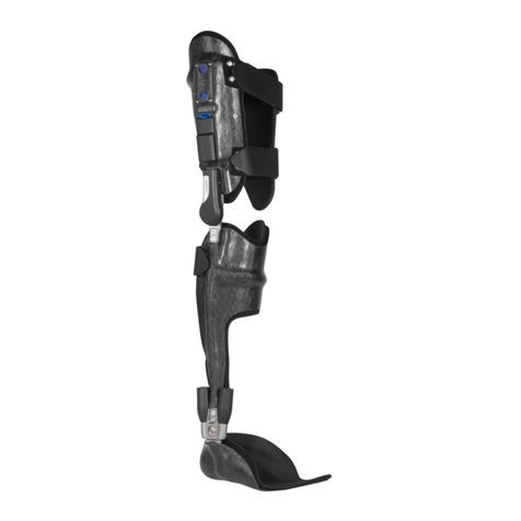
FHC FHC80 User manual
Other FHC Medical Equipment manuals
FHC
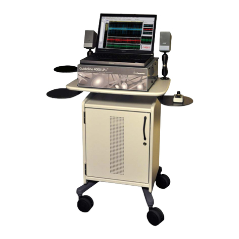
FHC Guideline 4000 LP+ Manual
FHC
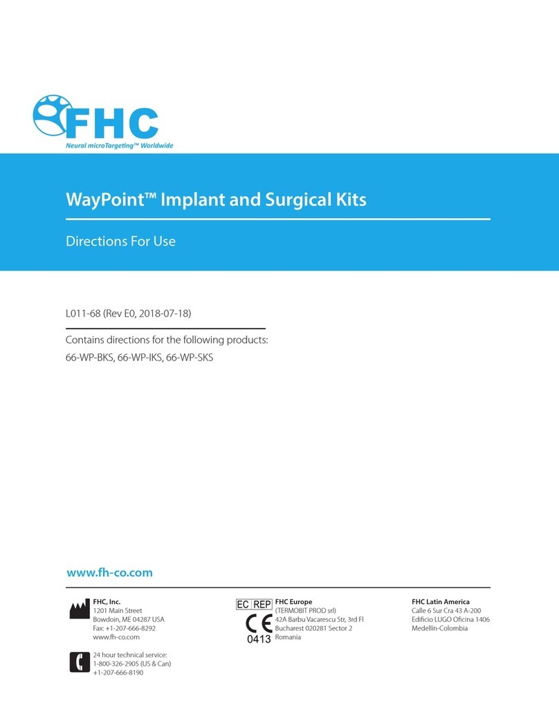
FHC WayPoint 66-WP-BKS Manual
FHC
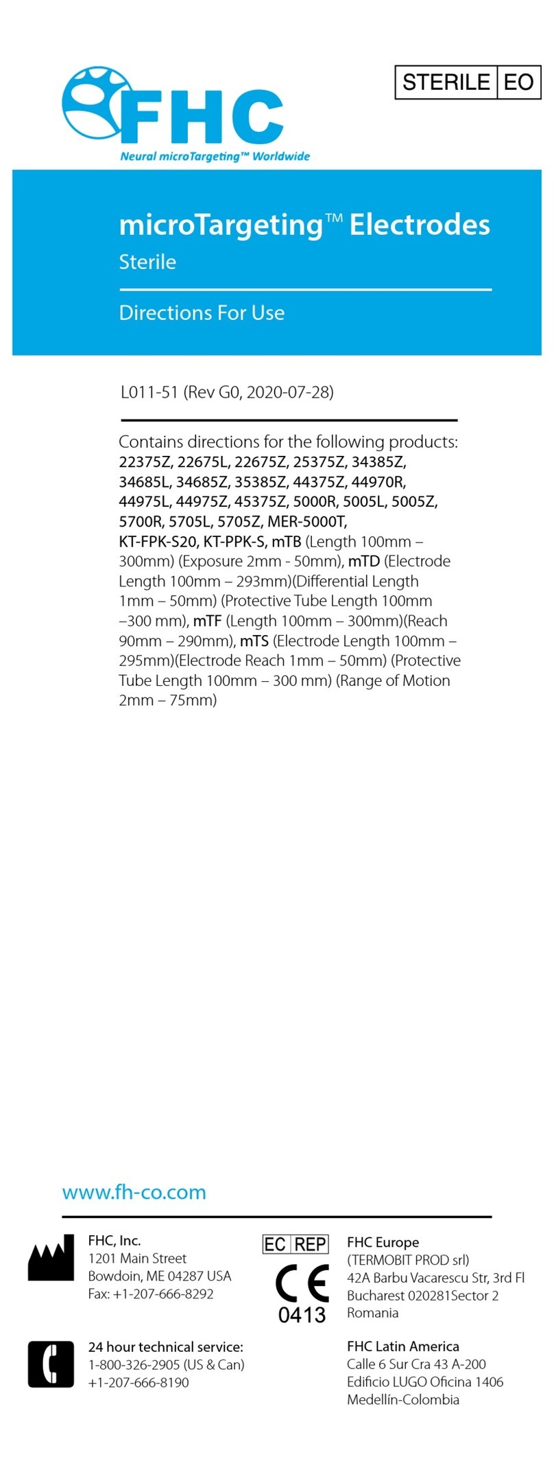
FHC microTargeting 22375Z Manual
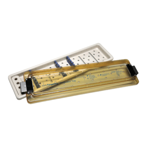
FHC
FHC microTargeting L011-46 Manual
FHC
FHC microTargeting 66-PT Series Manual
FHC
FHC Waypoint 66-IT-MR1 Manual
FHC
FHC microTargeting 22335Z Manual
FHC
FHC SPT1G User manual
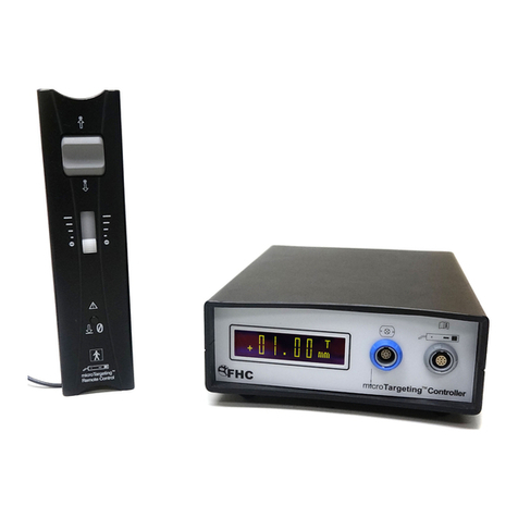
FHC
FHC microTargeting 66-DS-PA Manual
Popular Medical Equipment manuals by other brands
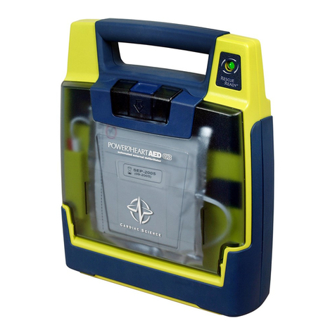
Cardiac Science
Cardiac Science Powerheart AED G3 Plus 9390A Operator's and service manual
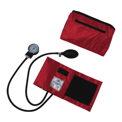
Medline
Medline CompliMates user manual

Brainlab
Brainlab VECTORVISION Series Technical user guide

ZOLL
ZOLL AutoPulse Quick Case instruction manual
Boston Scientific
Boston Scientific precision spectra Information manual
Nolta
Nolta 50 574232 Manual and safety instructions
Atos Medical
Atos Medical PROVOX TruTone Emote manual

Frontiermedical
Frontiermedical toto Quick reference guide
Otto Bock
Otto Bock E-MAG Active 17B203 Instructions for use
Respironics
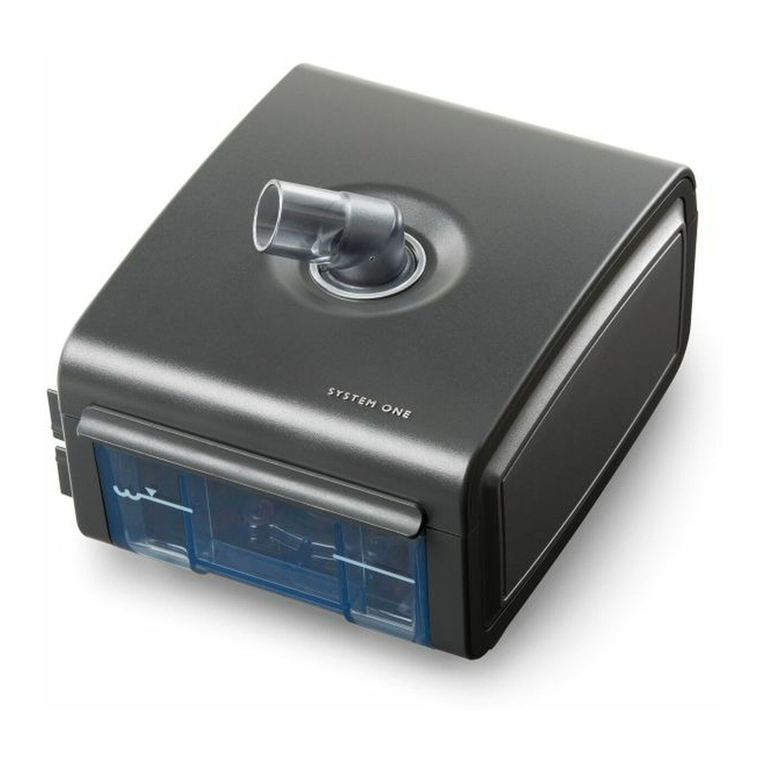
Respironics System One Heated Humidifier user manual
Seca
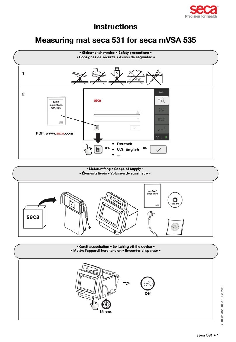
Seca 531 instructions
Roscoe Medical
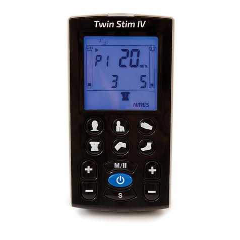
Roscoe Medical InTENSity Twin Stim IV instruction manual


