FHC WayPoint 66-WP-BKS Manual

WayPoint™ Implant and Surgical Kits
Directions For Use
L011-68 (Rev E0, 2018-07-18)
Contains directions for the following products:
66-WP-BKS, 66-WP-IKS, 66-WP-SKS
FHC, Inc.
1201 Main Street
Bowdoin, ME 04287 USA
Fax: +1-207-666-8292
www.fh-co.com
FHC Europe
(TERMOBIT PROD srl)
42A Barbu Vacarescu Str, 3rd Fl
Bucharest 020281 Sector 2
Romania
FHC Latin America
Calle 6 Sur Cra 43 A-200
Edificio LUGO Oficina 1406
Medellín-Colombia
24 hour technical service:
1-800-326-2905 (US & Can)
+1-207-666-8190
www.fh-co.com

L011-68 Rev. E0 2018-07-18 Page 2 of 11

L011-68 Rev. E0 2018-70-18 Page 3 of 11
Table of Contents:
Indications for use, Intended use, and Other devices required
Symbol Key
Storage
Warnings and Cautions
Inventory
Illustrative Procedure:
Implant Procedure
Scanning
Surgical Procedure
Track Selection
Track Offsetting Chart
4
4
4
5
6
7
7
8
9
11
11
L011-68 Rev. E0 2018-07-18 Page 4 of 11
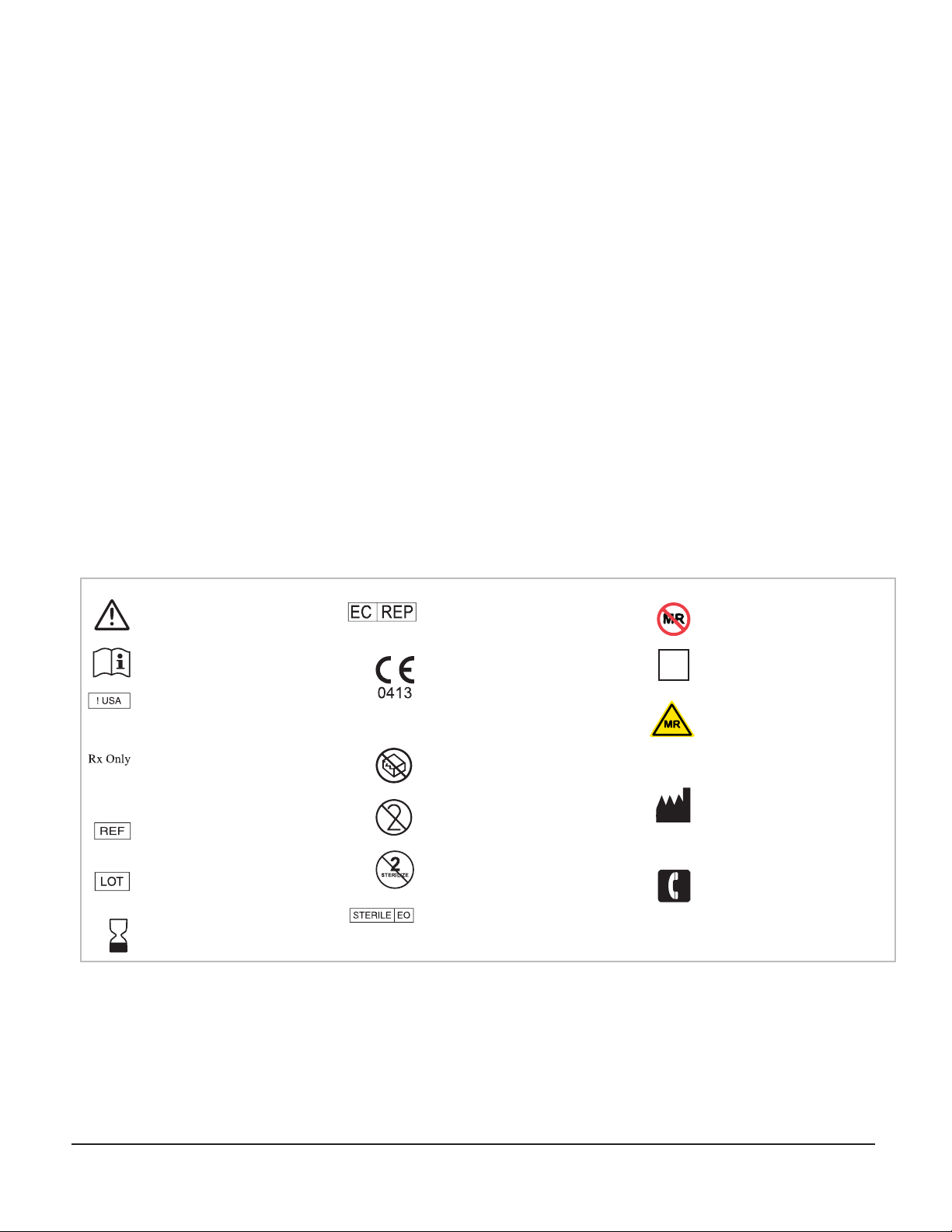
Symbol Key
WARNING / Caution, consult instructions
for important cautionary information.
Consult the instructions for use.
In reference to“Rx only”symbol; this
applies
to USA audiences only
Caution- Federal law (USA) restricts this
device to sale by or on the order of a
physician.
Indicates the catalogue number so that
the medical device can be identified.
Indicates the manufacturer’s batch code
so that the batch or lot can be identified.
The date after which the medical
device is not to be used.
Authorized Representative in the
European Community
European Conformity. This device fully
complies with MDD Directive 93/42/EEC
and legal responsibilities as a manufacturer
are with FHC, Inc., 1201 Main Street,
Bowdoin, ME 04287 USA.
medical device that should not be used if
the package has been damaged or opened.
Do not re-use; intended for one use on a
single patient, during a single procedure.
Medical device that is not to be resterilized.
Medical device that has been sterilized using
ethylene oxide.
Indications for use:
The WayPoint™ Implant and Surgical Kits are intended for use in neurosurgical procedures which require the accurate positioning of
microelectrodes, stimulating electrodes, or other instruments in the brain or nervous system.
Intended use:
The WayPoint™ Implant Kit is intended for use by medical personnel under the direction of a neurosurgeon in a clinical or operating
room, to place WayPoint™ fiducial anchors used to build a microTargeting™ stereotactic platform for one or more trajectories of a
neurosurgical procedure.
The WayPoint™ Surgical Kits are intended for use by a neurosurgeon in an operating room to attach a microTargeting™ stereotactic
platform to previously implanted fiducial anchors, and provide fixtures to position a microTargeting™ drive or other stereotactic de-
vice along the planned trajectory or at fixed offsets.
Other devices required:
• Compatible navigation software, such as WayPoint™ Navigator
• Patient specific microTargeting™ Platform built using fiducial anchor locations and desired trajectory
• Stereotactic device compatible with surgical kit positioners, such as microTargeting™ STar™ Drive
Storage:
Store the WayPoint™ Implant and Surgical Kits at normal room temperatures between 0°C (32°F) and 40°C (104°F). Do not exceed
104°F for long-term storage. Relative humidity should not exceed 95%.
MR Unsafe- an item that is known to
pose hazards in all MRI enviroments.
MR Safe- the item poses NO known
hazards in all MR environments
MR Conditional-an item that has been
demonstrated to pose no known
hazard in specicied MRI enviroments
with specified conditions of use.
Medical device manufacturer, as
defined in EU Directives 90/385/EEC,
93/42/EEC and 98/79/EC.
Telephone number
MR

L011-68 Rev. E0 2018-70-18 Page 5 of 11
Warnings and Cautions:
WARNING: Do not drill or install anchors in bone that is less than 4.5mm thick, or in bone that is weakened or diseased.
WARNING: Do not use anchors that exhibit any sign of looseness. Replace anchors and rescan if necessary.
WARNING: Do not allow WayPoint™ Anchors to remain implanted for more than 28 days.
WARNING: Do not overtighten screws or anchors as this could result in targeting errors.
WARNING: Complete kit is labeled MR Unsafe because it contains some MR Unsafe components. Refer to inventory
section for MRI status of individual components.
WARNING: Avoid trajectories close to parallel to the ground as this can cause accuracy errors due to flexing of the
plastic hubs and positioners.
CAUTION: Federal law (USA) restricts this device to sale by or on the order of a physician.
CAUTION: Sterilized by ethylene oxide
CAUTION: Sterile Medical Device - Do NOT resterilize
CAUTION: Do not use the contents if there is any evidence of damage to the package or package seal that could
compromise sterility.
CAUTION: WayPoint™ Implant and Surgical Kits are for single use only. Do not reuse. Cleaning or reuse may affect the
structural integrity and/or function of the device.These devices are difficult to clean after exposure to biological
materials and may cause adverse patient reactions if reused.
CAUTION: For the most secure fit of the WayPoint™ Anchors, advance drill and driver tools as perpendicular to the skull
as possible, and do not permit them to ‘wobble’ during advancement.
CAUTION: Avoid over tightening anchors as this can strip bone, or otherwise damage components.
CAUTION: Instruct the patient to avoid situations that could affect or disrupt the implanted anchors and to be cautious
about infection.
L011-68 Rev. E0 2018-07-18 Page 6 of 11
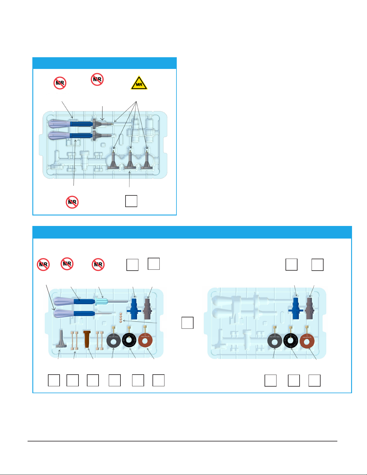
Inventory:
Combo Driver 5mm Fiducial Anchors
Anchor Wrench
Pilot Drill Driver
66-WP-SKS: Surgical Kit
Burr Hole
Marker
Burr Hole
Marker Bushing
Offset
Positioner
Center
Positioner
Standoffs
Anchor
Wrench
Thumb-
knobs
Standoff
Wrench
Entry
Offset Hub
Center
Hub
Target
Offset Hub
66-WP-BKS: Simultaneous Bilateral Kit
Offset
Positioner
Center
Positioner
WayPoint™ Implant Kit: 66-WP-IKS
MR
WayPoint™ Surgical Kits: 66-WP-SKS & 66-WP-BKS
Combo
Driver
MR MR
MR
MR MR MR MR MR MR
MR MR
Entry
Offset Hub
Center
Hub
Target
Offset Hub
MR MR MR
Removable
Combo
Driver Bit
L011-68 Rev. E0 2018-70-18 Page 7 of 11
Illustrative Procedure:
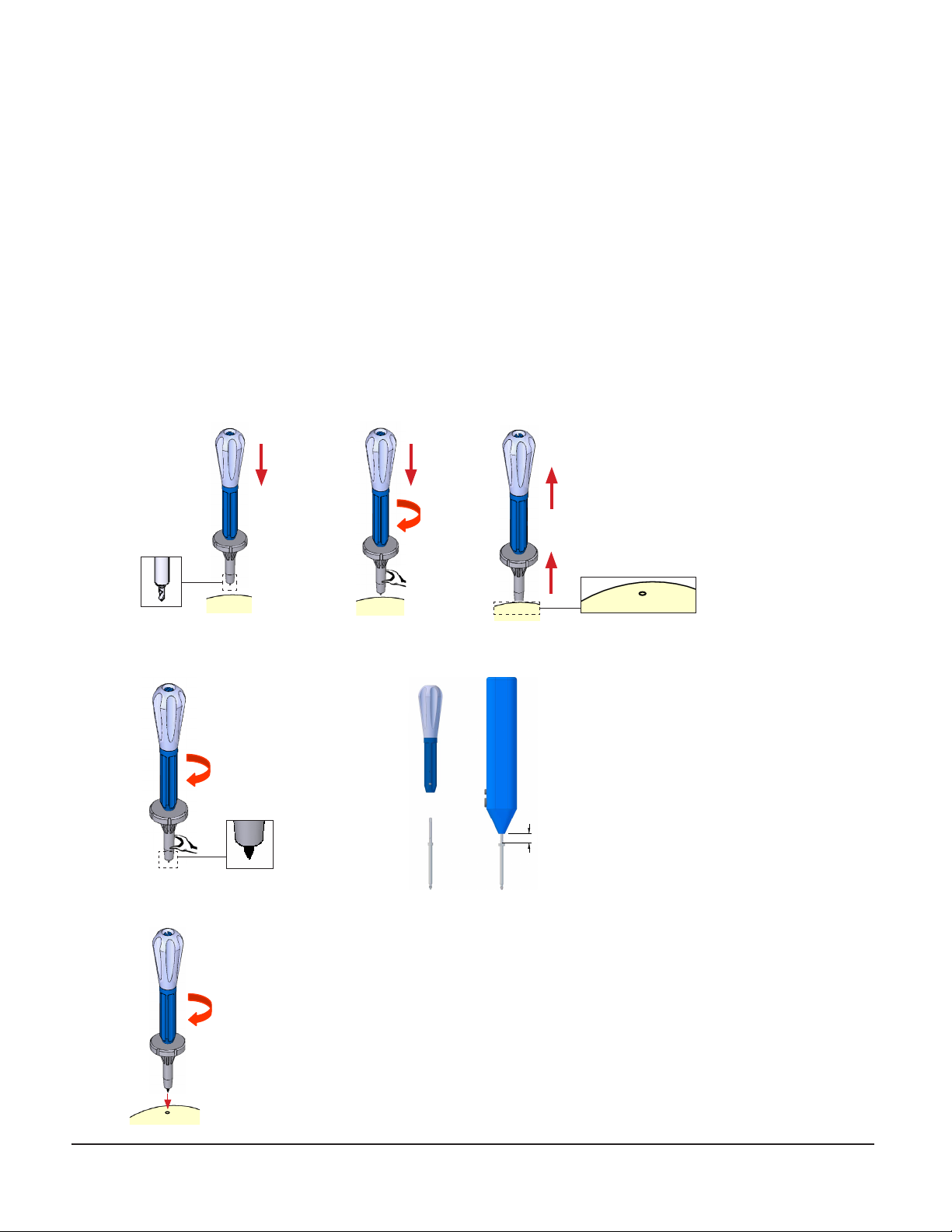
Implant Procedure
1. Follow aseptic technique throughout. The implant procedure does not need to be done in an OR setting.
2. Mark the intended anchor points on the patient’s scalp.
• Proper placement of the fiducial anchors is important to generate optimal platform geometry. The Fiducial Placement
Template DFU (L011-40-05) describes ideal anchor locations for each DBS platform model that can be easily measured
using the disposable fiducial placement template.
3. Using local anesthesia, for each anchor installation:
• Create a 10-15mm incision through scalp and muscle tissue and scrape the pericranium from the anchor site.
• Use the Pilot Drill Driver to create a pilot hole, particularly if the patient’s bone is dense or if the surgeon
encounters any difficulty fully seating the anchors.
• Secure the combination driver to the anchor preloaded in the wrench.
• Install the anchor in the skull with a clockwise rotation of the wrench and combination driver.
abc
~10mm
Note: The Combination driver bit can be removed
and used with the Osteomed Power Driver (68-OM-
SD). Pull the bit from the driver handle then insert
into the Osteomed power Driver. Note that the
collar bit will be approximately 10mm below the
power driver when fully inserted.
~10mm

L011-68 Rev. E0 2018-07-18 Page 8 of 11
• Use the wrench to support the anchor while twisting the driver counterclockwise out of the anchor.
• Inspect the attachment of the anchor to the skull. Anchors must be tight. Replace stripped anchors in a new location.
Note that if anchors are not fully seated in the skull, they should be tightened by hand with the hex wrench.
• Close each anchor wound over the anchor.
• Repeat this process for all remaining anchors.
4. Scan the patient (see next section).
5. Once scans have been checked to ensure that all anchors are displayed properly, patient may be released.
Scanning
WayPoint™ Anchors are CT visible. The patient’s head must be kept immobile while being scanned.
CT Scan requirements:
• Contiguous slices; no gaps between slices
• No overlapping slices
• Slice thickness no greater than 1.25mm
• Pixel size less than 1mm (0.5 to 0.8mm for best results)
• Gantry tilt angle of zero
Non-clinical testing demonstrated that the WayPoint™ Anchors are MR Conditional. A patient with this device can be scanned
safely, immediately after placement under the following conditions:
MR Scan requirements:
• Static magnetic field of 3-Tesla or less
• Maximum spatial gradient magnetic field of 720-Gauss/cm or less
• Refer to WayPoint™ Anchor/Locator Implantation Kit DFU (L011-40) for detailed MRI safety information on the WayPoint™
Anchors
MR image quality may be compromised if the area of interest is in the exact same area or relatively close to the position of the
WayPoint™ Anchor. Therefore, optimization of MR imaging parameters to compensate for the presence of this device may be
necessary.
abc
L011-68 Rev. E0 2018-70-18 Page 9 of 11
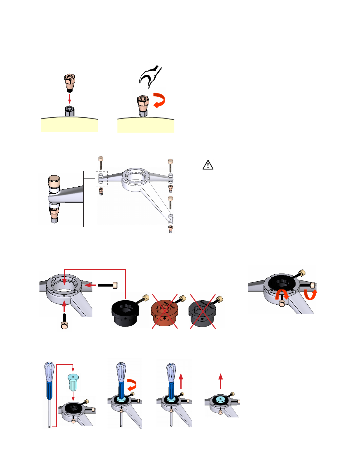
Surgical Procedure
1. Attach and handtighten standoffs to anchors.
2. Attach platform to standoffs with thumbknobs.
3. Attach the center hub to the platform using 2 screws at 90 degrees apart. Make sure the hub is completely seated in the
platform. The hub will sit approximately 1/8”above the top surface of the platform.
4. Use the burr hole entry marker with burr hole bushing and mark the skin and skull, then remove.
ab
ab
abc d
WARNING: Do not overtighten thumbknobs.
Only turn an additional 1/4 turn after
contacting mating surface.

L011-68 Rev. E0 2018-07-18 Page 10 of 11
5. Remove platform and drill burr hole.
6. Reattach platform.
7. Attach center drive positioner to center hub with tab oriented 45°, 90°, or 135° relative to screw. Make sure positioner is
completely seated in the hub.
8. Attach drive to positioner and secure following drive instructions.
9. Perform MER and implant lead.
10. Remove drive from positioner, then remove platform.
11. Use the standoff wrench to support the standoff while twisting the driver clockwise to secure it to the standoff. Turn
standoff wrench counterclockwise to remove standoff.
12. Use the anchor wrench to support the anchor while twisting the driver clockwise to secure it to the anchor. Turn anchor
wrench counterclockwise to remove anchor.
abc
a b c d
a b c d
13. Dispose of kit parts according to Hospital protocol.

L011-68 Rev. E0 2018-70-18 Page 11 of 11
3.5
3.0
2.12
2.0
1.41
1.0
.71
3.5
3.0
2.12
2.0
1.41
1.0
.71
3.5
3.0
2.12
2.0
1.41
1.0
.71
3.5
3.0
2.12
2.0
1.41
1.0
.71
Track Selection:
Center positioner (9 distinct tracks): Center track on target. Four parallel tracks with 2mm offset, ‘+’ configuration,
using positions A, C, E and G. Four parallel tracks with 2mm offset, ‘x’ configuration, using positions B, D, F and H.
Examples:
Center Positioner,‘+’ configuration,
using any of positions A, C, E or G,
indicated by the black dots in the
offsetting chart below.
Center Positioner,‘X’ configuration,
using any of positions B, D, F or H,
indicated by the red dots in the
offsetting chart.
3mm oset positioner (40 distinct tracks): Five parallel tracks with 2mm offset, center track offset 3mm from origin,
in eight configurations using positions A-H.
Examples:
3mm Offset Positioner in the‘G’ position,
indicated by the dark blue dots in the
offsetting chart.
3mm Offset Positioner in the‘B’
position, indicated by the magenta
dots in the offsetting chart.
Offsets beyond the 10mm range of the positioner may be reached with the target offset hub.
Track Osetting Chart
WARNING: The target offset hub creates a
new trajectory with target area orthogonally
offset 6mm from the original at the
microelectrode tip depth when the
physical drive reads 30mm. For platforms
with T<>30, the offset of 0.69mm per
10mm of drive travel may be used to
determine position at target depth.
WARNING: The entry offset hub creates a
new trajectory which is orthogonally offset
3mm from original at approximate entry
depth, and coincides with the original at
the microelectrode tip depth when the
physical drive reads 30mm. For platforms
with T<>30, the offset of 0.34mm per
10mm of drive travel may be used to
determine position at target depth.
This manual suits for next models
2
Table of contents
Other FHC Medical Equipment manuals


Popular Medical Equipment manuals by other brands

Active8rlives
Active8rlives Pulse Oximeter Bluetooth 4.0 manual

Sunrise Medical
Sunrise Medical Jay Care Back 3500 Series User instruction manual & warranty

NeoTract
NeoTract UroLift System UL400 Instructions for use

Synthes
Synthes LCP Surgical Technique Guide

B. Braun
B. Braun Infusomat compact plus P Instructions for use

Precision Medical
Precision Medical EasyFlow5 PM4300 Series user manual


