FHC microTargeting 66-DS-PA Manual

L011-80 (Rev C0, 2020-11-05)
Contains directions for the following products:
66-DS-PA, 66-EL-MS, 66-EL-RM, 66-DA-ME, 66-DA-SD
Directions For Use
microTargeting™ Controller Power Assist System
FHC, Inc.
1201 Main Street
Bowdoin, ME 04287 USA
Fax: +1-207-666-8292
24 hour technical service:
1-800-326-2905 (US & Can)
+1-207-666-8190
FHC Europe
(TERMOBIT PROD srl)
42A Barbu Vacarescu Str, 3rd Fl
Bucharest 020281Sector 2
Romania
FHC Latin America
Calle 6 Sur Cra 43 A-200
Edificio LUGO Oficina 1406
Medellín-Colombia
www.fh-co.com

Page 2 of 17 L011-80 Rev. C0 2020-11-05

L011-80 Rev. C0 2020-11-05 Page 3 of 17
Table of Contents:
Indications for use and Intended use
Symbol Key
Classifications
Operating Environment
Storage and Transport Conditions
Warnings and Cautions
Inventory
Cleaning
Replacing the Fuses
Installation and Functional Checkout
Sterile Draping Procedure
Illustrative Procedure
Basic pre-use checkout
Prepare the controller for use with the drive
Assemble and connect the motor unit
Zero the drive
Typical operative use
After completion of the procedure
Stall Detection
Reference Information
Carrying Case
Inspection
Warranty
Service/Repairs
Preventive Maintenance
End of Life Disposal
Technical Summary
Concepts and Terminology
Declarations of Electromagnetic Emissions and Immunity
4
4
4
5
5
5
6
6
6
6
7
8
8
8
9
10
11
12
12
13
13
13
13
13
13
13
14
15
16

Page 4 of 17 L011-80 Rev. C0 2020-11-05
Indications for use:
The microTargeting™ Drive System is intended to be used with commercially available stereotactic systems for neurosurgical
procedures which require the accurate positioning of microelectrodes, stimulating electrodes, DBS electrodes, or other instruments
in the brain or nervous system.
Contraindications: Follow the general guidelines concerning the suitability of neurosurgery involving the insertion of electrodes,
instruments or devices.
Intended use:
The microTargeting™ Controller Power Assist System is intended to be used by a neurosurgeon, neurologist or clinical
neurophysiologist to manipulate the position of depth electrodes, such that they may identify functional targets in the brain.
The device is expected to be used on patients undergoing stereotactic and functional neurosurgical procedures.
Symbol Key
Classifications:
The controller is an IEC 60601 Class 2 medical device with two applied parts:
• The drive motor, shrouded in a sterile drape sleeve is applied to the micropositioner which is itself attached to a
stereotactic frame which is attached to the patient. The drive motor is a type BF applied part.
• The hand-held remote control is intended to be held by the operator of the controller who may come into contact with
the patient. The remote control is a type BF applied part.
Note: The system does not directly interface with tissue or other parts of the body. It interfaces with the micropositioner
responsible for positioning a microelectrode in the brain.
WARNING / Caution, consult instructions for important
cautionary information.
Medical device manufacturer, as defined in EU Directives 90/385/
EEC, 93/42/EEC and 98/79/EC.
Consult the instructions for use. Telephone number
Caution- Federal law (USA) restricts this device to sale by or
on the order of a physician.
European Conformity. This device fully complies with MDD
Directive 93/42/EEC and legal responsibilities as a manufacturer are
with FHC, Inc., 1201 Main Street, Bowdoin, ME 04287 USA.
In reference to“Rx only”symbol; this applies to USA
audiences only. Authorized Representative in the European Community.
Indicates the catalog number so that the medical device
can be identified. Sterilized using ethylene oxide.
Indicates the serial number so that a specific medical
device can be identified.
A medical device that has not been subject to a
sterilizationprocess.
A medical device that should not be used if the package
has been damaged or opened. A medical device that is not to be resterilized.
Instructions for end of life disposal. Do not re-use; Intended for one use on a single patient, during a
single procedure.
+70°C
+158°F
-40°C
-40°F
The temperature limits to which the medical device can be
safely exposed.
1060
hPa
500
hPa
The range of atmospheric pressure to which the medical device
can be exposed.
100%
10%
The range of humidity to which the medical device can be
exposed. Not made with natural rubber latex.
Unit Symbols
Type BF applied part Auto retract
Motor unit Advance drive
Remote control Retract drive
USB interface Zero or origin
L011-80 Rev. C0 2020-11-05 Page 5 of 17
Operating Environment:
The controller and accessories are designed to be used in the normal operating room environment and require no special
handling or care exceptional to other electronic devices used in that environment. The controller and hand held remote control
should be positioned within 3 meters of but outside the sterile field, the motor unit is sleeved inside a sterile drape sleeve and
mounted on the drive within the sterile field.
Temperature Range: +5°C to +40°C
Relative Humidity Range: 10% to 95% (non-condensing)
Atmospheric Pressure Range: 500 hPa to 1060 hPa
Altitude: ≤ 2000 m above sea level
Storage and Transport Conditions
The microTargeting™ Controller Power Assist System should be stored and transported within the carrying case provided when
not in use.
Warnings and Cautions:
WARNING: To avoid risk of electric shock, this equipment must only be connected to a supply mains power outlet with
Protective Earth (3 pronged socket), never use a damaged power cord or power strip.
CAUTION: High voltage - there are no user serviceable parts internal to the controller housing, do not attempt to disassemble
the controller or any of its accessories.
WARNING: No unauthorized modification of this equipment is allowed.
WARNING: Do not block the vents on the bottom or back of the controller as this could cause it to overheat. Do not remove
the 4 rubber feet as this will cause the vents on the bottom of the controller to become blocked.
WARNING: Carefully route all system cabling away from high traffic areas.
WARNING: Do not manually rotate the drive knobs when the motor is attached as this could potentially damage the motor unit.
Note: To ensure optimal performance and minimize motor noise, the controller system should be serviced annually to tune the
controller’s drive circuit and speed settings to compensate for normal motor wear.
WARNING: Do not use the controller in the presence of flammable gas mixtures.
WARNING: Do not attempt to sterilize the motor unit or the hand held remote control.
WARNING: Expected target depth can change based on the stereotaxy and electrodes used. Ensure the target depth is set
correctly when running the controller in distance to target mode.
WARNING: Always zero the controller prior to inserting electrodes.
WARNING: Periodically (every 5mm is recommended) verify that the depth reported by the controller matches that shown on
the drive scale.
WARNING: If power to the controller is temporarily interrupted, it will need to be re-zeroed prior to resuming its use.
CAUTION: Medical electrical equipment needs special precautions regarding EMC and needs to be installed and put into
service according to the EMC information provided in the Declaration of Electromagnetic Emissions section of this document.
CAUTION: Portable and mobile RF communications equipment can affect medical electrical equipment.
WARNING: The controller should not be used adjacent to or stacked with other equipment. Where such an arrangement is
necessary, the controller should be observed to verify normal operation prior to use.
CAUTION: Federal law (USA) restricts this device to sale by or on the order of a physician.
Rx only
Page 6 of 17 L011-80 Rev. C0 2020-11-05
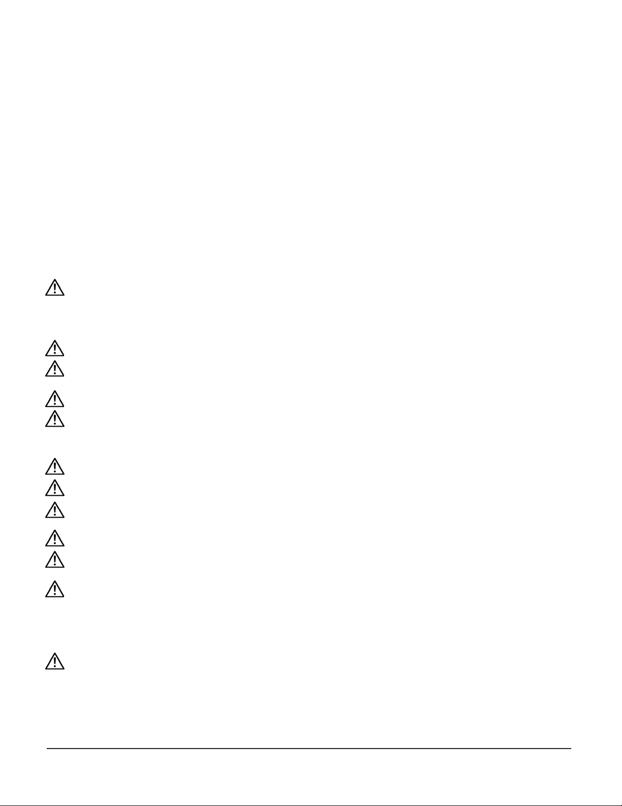
Inventory:
Storage case: 66-DA-SC (Left to right) Motor unit: 66-DA-ME
Display module: 66-EL-MS, Remote control: 66-EL-RM
USB cord: N5-55-02,
Power cord: (country specific)
Accessory - Sterile Drape Sleeve: 66-DA-SD
Cleaning:
In the event that any components of the microTargeting™ Controller Power Assist System become contaminated or soiled they
should be disconnected from power sources and wiped clean with an isopropyl alcohol dampened cloth, then wiped dry before
they are returned to the carrying case. Do not immerse any components of the system in fluids or allow excessive moisture to
remain.
Replacing the Fuses:
Should the fuses require replacement:
1. Unplug power cable before attempting fuse replacement.
2. Pinch together spring tabs to release fuse drawer from power
entry (see arrows).
3. Remove spent fuses from fuse drawer.
4. Insert two replacement fuses into fuse drawer.
5. Slide fuse drawer with fuses into power entry. Spring tabs
will snap into place once drawer is fully seated.
Installation and Functional Checkout:
Prior to its initial use, set up the microTargeting™ Controller Power Assist
System for an initial installation checkout. Practicing the mounting and
engagement procedure and the assembly draping procedure several
times before the first surgical use will familiarize personnel with the
required steps.
The proper functioning of the remote control and the measuring function of the display can be verified by advancing the drive
several times in 10mm increments, then returning to 0.00, comparing the physical scale at each step to the displayed position. There
should be no discrepancy in the readings, no movement of the drive in the remote control’s rocker switch center position and no
movement of the drive as long as the speed selection slider is set to “zero”, regardless of the state of the rocker switch.
Any error may indicate that the controller or the drive is not functioning correctly.
FHC Part Number: E1-06-09
Fuse Type: 5 x 20mm 250VAC 1Amp Slow Blow

L011-80 Rev. C0 2020-11-05 Page 7 of 17
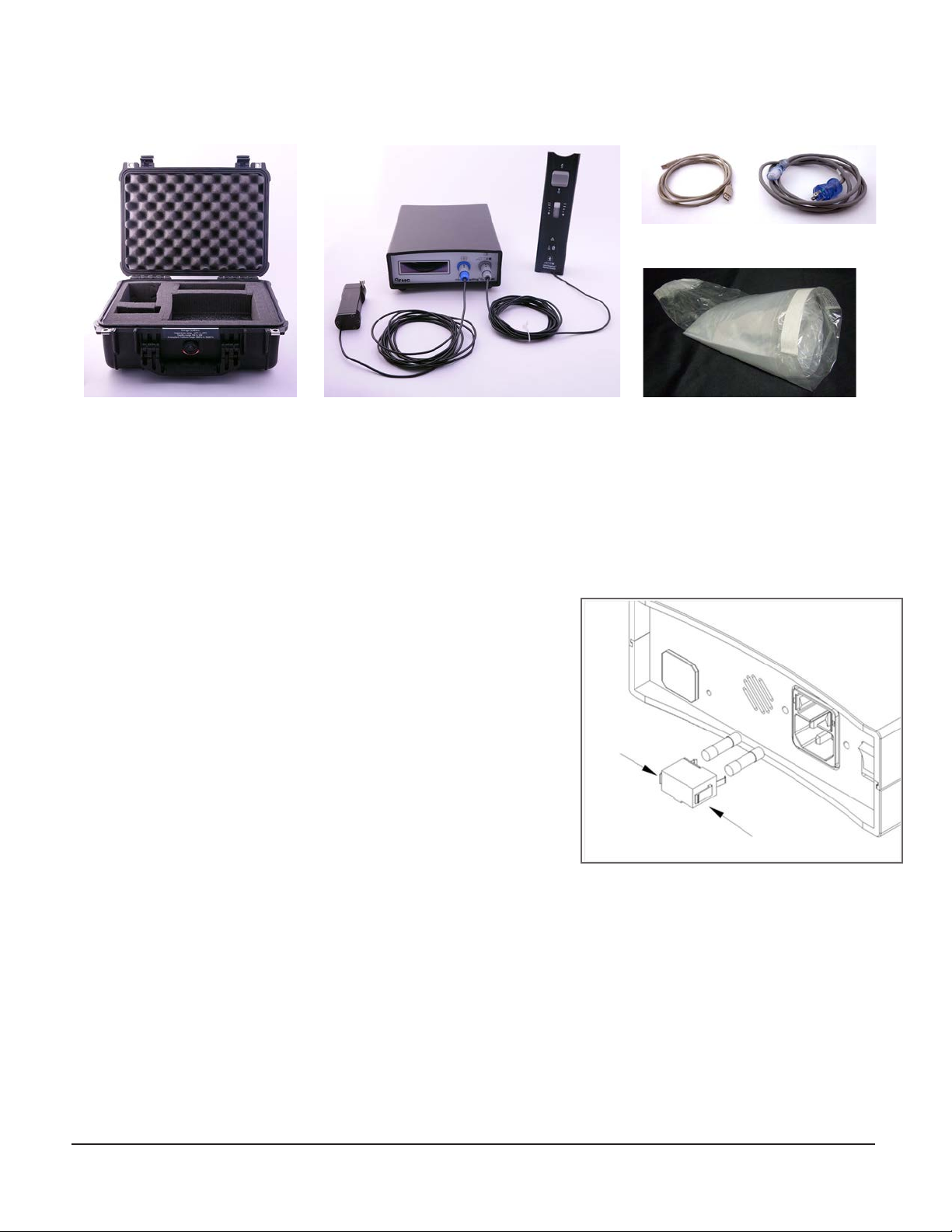
Sterile Draping Procedure:
1. Draping the motor can be accomplished by one person,
but is facilitated if an assistant is present. The one-person
method will require a sterile gloved hand ( ) for
the drape. The other hand will be a non-sterile hand
( ) after handling the motor. Most will find that the
motor hand should be the least favored hand. The
two-person method requires a sterile gowned and gloved
person ( ) to handle the drape and an assistant
that will have non-sterile gloves ( ) after handling
the motor. Normal draping precautions will suffice. A
practice draping should be done before first surgical use.
2. (or prior to putting on sterile gown and gloves) -
Remove the protective storage cap from the motor.
Coil the cable and place it on a flat surface so that the
motor can be picked up with its cable in one hand.
3. - Remove the drape from its sterile packaging
and expand the opening to allow entry of a hand. Do
not pull any of the folds out at this time. (If one person,
remove the included elastic bands from their tape
holder and place on a sterile surface.)
4. - Holding the non-sterile motor with the pins
pointing away from you, and the coiled cable in the
same hand, insert it into the drape, being careful not
to touch the outside of the drape.
5. - Push the drape over hand so the motor
and cable are all the way at the end of the sleeve.
6. and - Maneuver the drape and motor so
that the two alignment pins and the center drive plate
are entering the cutouts in the end of the drape.
s
s
s
s
s
7. and - Push the pins
and center drive plate through
the cutouts and smooth the
stretchable end of the drape
over the assembly.
8. - Take the elastic bands and stretch them over
the assembly, using at least two wraps. Be careful to
smooth any wrinkles from the mating flat surface of
the assembly as this is done but do not touch the pins
or drive plate. Ensure the wraps are above the flanges
on the assembly to prevent slipping.
v
9. - Hold the drape with the assembly inside
while pulls the cable from the drape. Be careful
not to touch the pins protruding from the end of the
drape.
10. - Unfold the drape carefully as the cable is
withdrawn. When the cable is out of sterile envelope
distance, can hold both cable and drape.
11. - Using the tape that the
elastic bands came in pull in the
folds of the drape tightly above
the assembly and tape neatly. If
no assistant is helping, this can
be done after changing the
non-sterile glove.
12. -The assembly cable can be plugged into its
receptacle, or -the whole draped apparatus set
aside on a sterile surface awaiting the surgery. In this
case it is best to leave the cable inside the drape and
to not unfold the drape more than necessary until it is
needed.
s
s
s
s
s

Page 8 of 17 L011-80 Rev. C0 2020-11-05
Illustrative Procedure:
Basic pre-use checkout
1. Visually inspect the components that are going to be used prior to the procedure. Ensure that:
• No major physical damage (beyond what can be expected under normal use conditions, such as minor
scratches of the surface) can be seen on the enclosures of the controller or the remote control
• None of the cables that are to be used are frayed, kinked or otherwise damaged
• The connectors are not damaged and are securely attached to the cables they terminate
• Position the controller module such that the mains power switch on the back panel is easily accessible
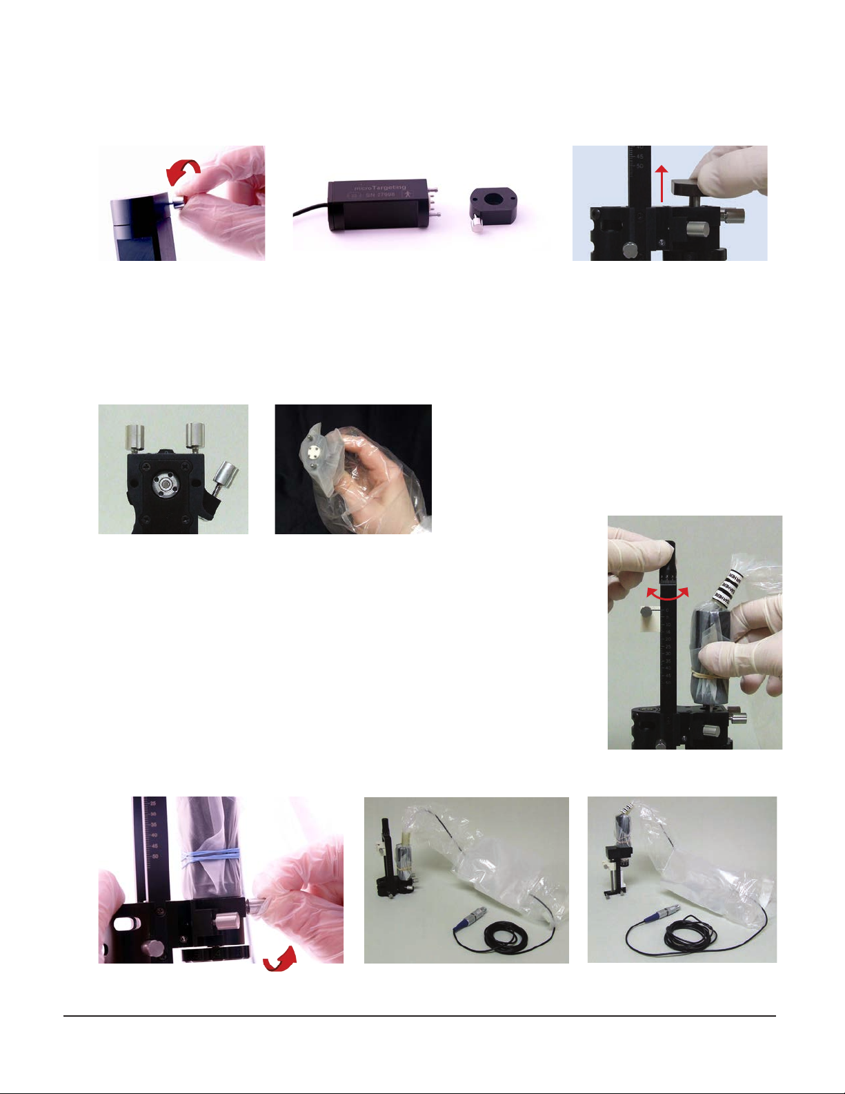
Prepare the controller for use with the drive
2. Connect the controller module to mains, using the provided power cable.
3. Connect the remote control to the controller module by plugging the remote control’s connector into its socket
on the front panel.
4. If you plan to interface the controller with an MER system or any other compatible device or application, remove
the protective cover and connect it to the computer using the USB cable provided.
Back panel
Remote control
Front panel
Remote control’s connector and socket
L011-80 Rev. C0 2020-11-05 Page 9 of 17
Assemble and connect the motor unit
5. Remove the sterilization cover on the motor unit and the drive, if they are attached.
6. The motor unit must be draped to maintain sterility of the drive, it should not be sterilized. For detailed step by step
instructions on the proper draping of the motor unit while maintaining sterility, please refer to the “Sterile Draping
Procedure”on page 6 , or see the Directions For Use which accompanied the drive system.
7. Mount the draped motor unit on the drive by inserting the two long alignment pins into the mating holes on the drive.
There is no incorrect way to align the pins. Do not force the assembly any farther at this time.
8. Push down lightly on the motor unit while turning the drive advancement knob slowly.
9. The motor unit’s center drive plate pins must be exactly aligned with the mating holes in
the drive before they will engage. The knob should be turned slowly in small increments.
Engagement should happen within 90 degrees of knob rotation.
10. When the pins are felt to engage, push the motor unit all the way down to the mating
surface of the drive. Make sure no folds of the sterile drape are caught between the
surfaces. This should require little effort, and any restriction will require realigning the
pins or removal and inspection of the drive and motor for obstructions or damaged
components.
11. Tighten the motor locking knobs on the drive securely and test the assembly for secure
attachment.
Motor unit attached to STar™ Drive and microTargeting™ Drive
Page 10 of 17 L011-80 Rev. C0 2020-11-05
12. Plug the motor unit into the controller by inserting its connector into the corresponding socket on the front
panel.
Zero the drive
13. Activate the ON/OFF switch of the controller module. The controller should boot and display the“Set drive origin”
message.
14. If an initial offset is to be used, it should be programmed into the controller now. Note that the initial offset will
reset to 0mm every time the power to the controller is cycled.
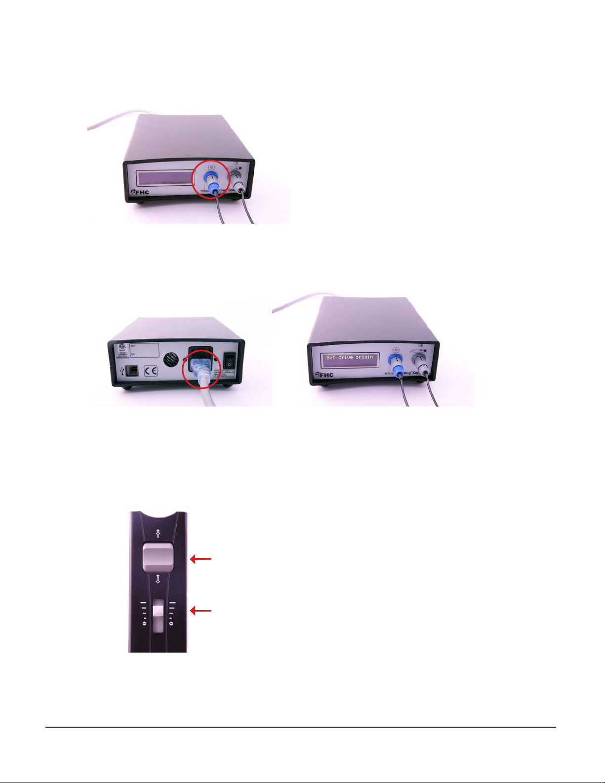
15. Select a speed using the speed selection slider on the remote control. Using the rocker switch, advance or retract
the drive as needed until the drive is positioned at exactly 0 µm or the initial offset location if specified.
Rocker switch
Speed selection slider

L011-80 Rev. C0 2020-11-05 Page 11 of 17
16. Press the zero button on the remote control to indicate that the current position is at 0 µm. From now on, pressing and
holding down the Zero button for 3 seconds will return the drive to this position.
17. If connecting to an MER system, verify that the current depth is appropriately displayed on that system.
Typical operative use
18. Mount the assembled drive on the stereotactic system.
19. Load the insertion tube and electrode.
20. Control the position of the electrode(s) as follows using the remote control:
• Set the desired motion speed using the speed selection slider. When set to 0, no motion will occur. Sensible defaults are
provided for the other speed steps, but they can be adjusted through the USB Interface.
• Pressing and holding the rocker switch on the remote control in its“Advance”position will cause the drive to advance
towards the target at the set speed for as long as the rocker switch is held. Releasing the rocker switch will immediately
stop any motion.
• Pressing and holding the rocker switch on the remote control in its“Retract” position will cause the drive to be retracted
away from the target at the set speed for as long as the rocker switch is held in the “Retract” position. Releasing the rocker
switch will immediately stop any motion.
Zero button
Advance
Retract

Page 12 of 17 L011-80 Rev. C0 2020-11-05
21. Navigate to the expected position of the target using the controls described above. For MER recording, motion artifact
will be significantly reduced by selecting a lower rate of advance.
22. Decrease the speed for fine position adjustment and advance or retract the electrode until the target is reached and
the necessary procedure performed.
23. Returning to the starting point: pressing and holding the zero button on the remote for three seconds will cause
the controller module to return the drive to its starting position at the maximum possible speed. This motion can be
interrupted by pressing the rocker switch in any direction or by changing the current speed selection using the speed
selection slider. Returning to zero can also be performed at a controlled speed by simply retracting the drive using the
rocker switch.
24. The motor unit can be removed from the drive at any point during the procedure and the operation can proceed using
the manual control and visual scale on the drive.
After completion of the procedure
25. Remove the motor unit, discard the sterile drape and return the sterilization covers to their positions on top of the drive
and on the motor unit.
26. Unplug the remote control and power cord. Store the controller unit and all its accessories in the carrying case.
Stall Detection
The torque of the stepper motor is quite high, especially when amplified by the drive screw, but the motor can be made to
stall if it encounters a physical obstruction or if the operator attempts to use the manual drive advancement knob while the
motor is operating. This is especially true at higher speeds. While this is a situation that should not occur during normal use,
a stall detection algorithm has been provided.
If a stall is detected during drive movement, the word “STALL” will appear, replacing the position number on the display, and
the drive will stop moving for approximately 5 seconds to alert the operator that a stall has occurred. Then the position will
be redisplayed and the drive will continue moving at the speed controlled by the remote. The number displayed should
be checked against the drive’s physical scale. There may be no noticeable difference due to the sensitivity of the detection
routine. A small discrepancy of less than 25 microns should not be a cause for concern.
Discrepancies of over 25 microns or frequent stall indications may require that the motor unit be removed and the manual
advancement knob be used to complete the procedure. Frequent stall indications are a sign that there may be a physical
problem with the drive resulting in excessive torque requirements, or a problem with the motor unit or controller. Contact
FHC for additional diagnostic help and to set up a repair.

L011-80 Rev. C0 2020-11-05 Page 13 of 17
Reference Information:
Carrying Case
The carrying case used for shipping is intended to be used as a protective case during shipping, storage and transport of the
system. It has been designed to protect the system from damage. It is lined with a foam interior which has been customized to
hold the microTargeting™ Controller Power Assist System components. There is available space to add additional equipment if
desired, the foam is pre-cut and additional compartments may be made by removing appropriate foam sections. The carrying
case is not intended for use as a sterilization case, none of the components of the microTargeting™ Controller Power Assist
System require sterilization. The foam lining of the case cannot be cleaned. If it becomes soiled or contaminated, contact FHC
for a replacement lining.
Inspection
All FHC products undergo a rigorous quality assurance inspection at the factory but should be carefully inspected before use.
If any exterior damage to the shipping carton is noted, the instrument should be inspected for obvious physical damage. The
contents of each package should be physically checked against the list in the inventory section to ensure all parts have been
received.
Warranty
All FHC products are unconditionally guaranteed against defects in workmanship for one year from date of shipment as long as
they have been exposed to normal and proper use. Even though the one year warranty may have expired, please contact our
service department before attempting any repairs or alterations. Many of these repairs will still be performed at the factory at no
charge to the customer.
Service/Repairs
Should service be required, please contact our service department for return instructions at 1(800)326-2905 or
+1-207-666-8190. Carefully pack the instrument and all accessories in the provided carrying case before returning.
All returns must be clean and free of biological contamination.
Please include a note indicating:
1. The Returned Material Authorization (RMA) Number provided by the service department
2. The name and contact information of a person to contact if questions arise.
3. The “symptoms” indicating that repair is necessary.
4. A statement that the instrument is being shipped free of any biological contamination.
Preventive Maintenance
The components of the drive accessories are not user repairable or serviceable. For continued optimal performance,
contact FHC to arrange a periodic preventive maintenance service. In most cases, this can be done on site. FHC
recommends an annual preventive maintenance contract for this purpose. Included with a preventive maintenance
contract are free firmware upgrades for functional enhancements as they become available and free service and repair
should any problems arise.
End of Life Disposal
In order to be environmentally responsible, the microTargeting™ Controller Power Assist System should not be
disposed of in a landfill or with municipal waste. FHC will gladly recycle the system once it has reached its end of
life in an environmentally responsible manner. Please contact your local FHC representative for instructions on
where to return the microTargeting™ Controller Power Assist System.

Page 14 of 17 L011-80 Rev. C0 2020-11-05
Technical Summary:
Physical Dimensions
Controller Module Hand-held Remote Motor
3 cm
8 cm
2 cm
0.1 kg
5 cm
4 cm
19 cm
0.2 kg
16 cm
7 cm
21 cm
0.8 kg
Width
Height
Length
Weight
Mechanical and Material Profile
Case Material:
Display:
ABS, Non-conductive, UL94 V-O
16x2 Character Display, Yellow
Wide (120O) viewing angle
Electrical Specifications
Power Supply:
Power Consumption:
100-240 VAC, 50/60 Hz internal power supply
10W max.
Medical Profile
Medical Certification:
Sterilization:
AAMI/IEC 60601 3rd Ed.
Do not sterilize
Performance Specifications
Linear Resolution:
Long Term Linear Accuracy:
Minimum Speed:
Maximum Speed:
Acceleration/Deceleration:
Travel Rates:
Safety Features:
1 µm
25 µm
1 µm/s
500 µm/s
1800 steps/s - Quickly reaches target speed, avoiding resonance
4 User-adjustable speeds between 1 and 500 µm/s
System watchdog automatically resumes safe operation in case of malfunction
Redundant position tracking systems
Stall detection and un-driven motion monitoring
Noise Figures
Improvement over legacy design: 40% less mechanical noise
Connectivity
PC Interface:
Operating Systems:
USB 2.0 with RS-232 Emulation (19.2kBPS)
Windows XP, Vista, 7, 8, 8.1, 32/64-bit

L011-80 Rev. C0 2020-11-05 Page 15 of 17
Concepts & Terminology:
Auto-Retract: Pressing and holding the zero button for approximately three seconds will initiate the auto-retract function. Once initiated,
the controller will retract the motor at top speed to the origin point. If an initial offset has been specified, this is where the drive will stop.
Initiating the auto-retract function while at the initial offset origin will cause the drive to retract to the zero point. Pressing any control
during the auto-retract cycle will immediately cancel the auto-retract cycle.
Display Mode: The controller can be configured to display the current depth value in distance from zero mode where it will always match
the reading obtained from the scale of the drive or in distance from target mode where the target depth will be the zero point with positive
depth values below target and negative values above.
Display Units: The controller can be configured to display the current depth in microns (XXXXXµm) or in millimeters (XX.XXmm) according
to user preferences.
Drive: The micropositioner, this should be either a microTargeting™ Drive or a STar™ Drive.
Initial Oset: When desired, the origin point used while zeroing the drive need not be the 0 mm mark of the drive. If desired, an initial
offset value can be entered through the USB interface to begin the procedure at a depth other than zero. For instance, if an initial offset of
15mm is entered, to zero the drive – one would position it at the 15mm mark and press the zero button. The initial offset value will reset to
0mm every time the controller is powered down.
Language Support: The controller is capable of displaying all front panel information in numerous languages. The language setting is
changed through the USB interface. Supported languages include: English, French, German, Italian, Spanish, Danish, and Swedish (others
may be added in later updates).
Limit: A depth limit value that can be entered through the USB interface. The controller will not allow the drive to be advanced beyond
this point. The limit value will be retained when the controller is powered down and is set to 50mm by default. Note that both the
microTargeting™ Drive and the STar™ Drive provide a physical stop at approximately 55mm.
Querying Settings: The current settings for initial offset, target and limit depths will be displayed by the controller when the zero button is
pressed any time after zeroing the drive.
Speeds: There are four speed options available, they can be set from 1 micron per second up to 500 microns per second. The default drive
speeds are set to: 10, 50, 225 and 500 µm/s. These can be adjusted through the USB interface according to preferences. To select a speed,
simply adjust the speed slider switch on the remote control. The first speed position of the slider switch is always STOP (or 0 microns per
second) and will prevent the controller from moving.
Stop Points: The controller can automatically stop advancing periodically to facilitate MER, once every mm for instance. Through the USB
interface, one sets a step size then presses and holds the Advance rocker switch on the hand held remote control. The controller will
automatically stop advancing once the step size distance has been traveled. To advance to the next stop point, one releases the advance
button and re-engages it. Alternately, one can issue a GO command through the USB interface to resume advancing.
Target: The depth at which the target is expected to be reached can be set to any value between the initial offset and the limit values.
The target value will be retained when the controller is powered down and is set to 30mm by default.
USB Interface: The controller’s USB interface emulates a serial (COM) port. When first plugged into a PC, the driver for the controller will
be installed and a virtual COM port will appear. To establish communications with the controller, a terminal emulator application will need
to be installed and run on the PC (such as Window’s HyperTerminal). Baud rate should be set to 19200 bps, 8 bit words. See the reference
information section for a description of commands supported.
User Proles: The controller can save and store up to 5 different user profiles to allow users to easily configure the controller according to
different user’s speed preferences and/or optimized settings for different types of procedures. A user profile contains all available speed
settings. Profiles are loaded and saved through the USB interface.
Zeroing the Drive: Mounting the motor unit onto the drive and using the hand held remote control to adjust the drive depth to the
origin. Once the drive is positioned at the origin, press the zero button on the hand held remote control and the depth of the drive will
be tracked by the controller for the remainder of the procedure.

Page 16 of 17 L011-80 Rev. C0 2020-11-05
Declarations of Electromagnetic Emissions and Immunity
Declaration of Emissions:
The mT Controller is intended for use in the electromagnetic environment specified below. The operator should ensure that
it is used in such an environment. The mT Controller is suitable for use in all establishments, other than domestic, and those
directly connected to the public low-voltage power supply network that supplies buildings used for domestic purposes.
Emissions Test Compliance Electromagnetic Environment – Guidance
RF Emissions CISPR 11 Group 1 The mT Controller uses RF energy only for its internal function. Therefore, its
RF emissions are very low and are not likely to cause any interference in near-
by electronic equipment.
RF Emissions CISPR 11 Group 2 The mT Controller must emit Electromagnetic energy in order to perform its
intended function. Nearby electronic equipment may be affected.
RF Emissions CISPR 11 Class A or B Class A
Harmonics IEC 61000-3-2 Class A Class A
Flicker IEC 61000-3-3 Complies Complies
Declaration of Immunity:
The mT Controller is intended for use in the electromagnetic environment specified below. The operator should ensure that it
is used in such an environment.
Immunity Test IEC60601 Test Level Compliance Level Electromagnetic Environment - Guidance
ESD
IEC 61000-4-2
±6kV Contact
±8kV Air
±6kV Contact
±8kV Air
Floors should be wood, concrete or ceramic tile. If
floors are synthetic, the r/h should be at least 30%
EFT
IEC 61000-4-4
±2kV Mains
±1kV I/Os
±2kV Mains
±1kV I/Os
Mains power quality should be that of a typical
commercial or hospital environment.
Surge
IEC 61000-4-5
±1kV Differential
±2kV Common
±1kV Differential
±2kV Common
Mains power quality should be that of a typical
commercial or hospital environment.
Voltage
Dips/Dropout
IEC 61000-4-11
>95% Dip for 0.5 Cycle
60% Dip for 5 Cycles
30% Dip for 25 Cycles
>95% Dip for 5 Seconds
>95% Dip for 0.5 Cycle
60% Dip for 5 Cycles
30% Dip for 25 Cycles
>95% Dip for 5 Seconds
Mains power quality should be that of a typical
commercial or hospital environment. If the
user of the mT Controller requires continued
operation during power mains interruptions,
it is recommended that the mT Controller be
powered from an uninterruptible power supply
or battery.
Power Frequency
50/60Hz
Magnetic Field
IEC 61000-4-8
3A/m 3A/m Power frequency magnetic fields should be that
of a typical commercial or hospital environment.
Conducted RF
IEC 61000-4-6
Radiated RF
IEC 61000-4-3
3 Vrms
150 kHz to 80 MHz
3 V/m
80 MHz to 2.5 GHz
(V1)=3Vrms
(E1)=3V/m
Portable and mobile communications equipment
should be separated from the mT Controller
by no less than the distances calculated/listed
below:
D=(3.5/V1)(Sqrt P) 150kHz to 80MHz
D=(3.5/E1)(Sqrt P) 80 to 800 MHz
D=(7/E1)(Sqrt P) 800 MHz to 2.5 GHz
where P is the max power in watts and D is the
recommended separation distance in meters.
Field strengths from fixed transmitters, as
determined by an electromagnetic site survey,
should be less than the compliance levels (V1
and E1).
Interference may occur in the vicinity of
equipment containing a transmitter.

L011-80 Rev. C0 2020-11-05 Page 17 of 17
Recommended Separation Distances:
The mT Controller is intended for use in the electromagnetic environment in which radiated disturbances are controlled. The
customer or user can help prevent electromagnetic interference by maintaining a minimum distance between portable and
mobile RF Communications Equipment and the mT Controller as recommended below, according to the maximum output
power of the communications equipment.
Max Output Power
(Watts)
Separation (m)
150kHz to 80MHz
D=(3.5/V1)(Sqrt P)
Separation (m)
80 to 800MHz
D=(3.5/E1)(Sqrt P)
Separation (m)
800MHz to 2.5GHz
D=(7/E1)(Sqrt P)
0.01 0.116667 0.116667 0.233333
0.1 0.368932 0.368932 0.737865
0 1.166667 1.166667 2.333333
10 3.689324 3.689324 7.378648
100 11.66667 11.66667 23.33333
This manual suits for next models
4
Table of contents
Other FHC Medical Equipment manuals


Popular Medical Equipment manuals by other brands


Huvitz
Huvitz HOCT-1 user manual

Hardy Diagnostics
Hardy Diagnostics The Wizard CompactDry Reader operating instructions

Mettler Electronics
Mettler Electronics Sonicator Plus 930 instruction manual

Amico
Amico Diagnostic Station Instructions for use

Dynatronics
Dynatronics Hausmann 6175 Installation & operation instructions

laerdal
laerdal SimPad quick start guide


