FHF AVISA AX08 User manual
S under AX08 and
S under-Str be-C mbinati n AXL08
FHF BA 6032-10 04/11 1
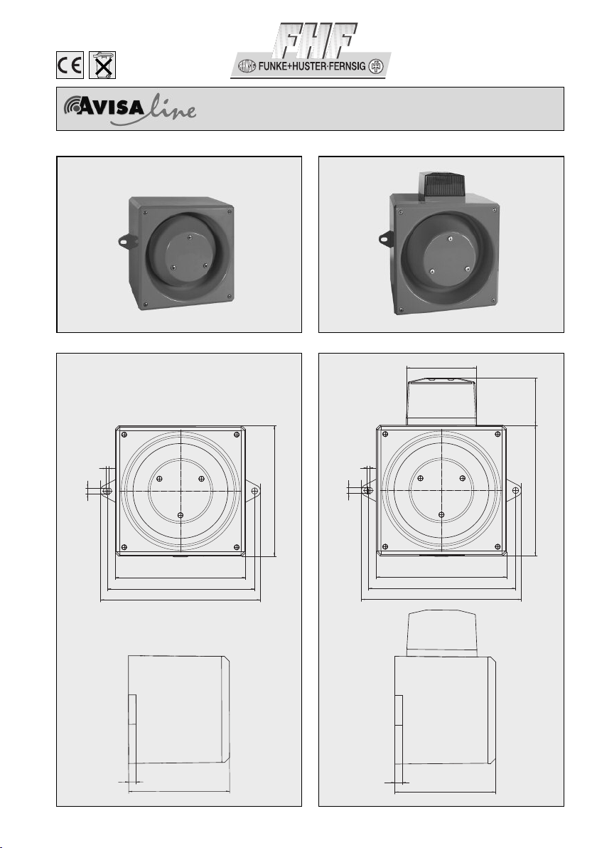
Dimensi ns
AX08
Dimensi ns
AXL08
AX08 AXL08
269
250
216
4
216
ø 10
14 153
269
250
216
216 57,5
ø 10
88
153
14
4

2
Housing Polycarbonate
Colour Red, similar to RAL 2002
Insulation class II
Protection degree IP 65 acc. to IEC 60529
Cable gland
intended for M20 x 1.5 or Self-sealing grommet
Volume approx. 116 dB(A) (depending on signal tone)
Signals
32 different signal tones (see diagrams), 2nd stage can be turned on externally
Temperature range
Operation
-25 C
to
+55 C
Storage
-40 C
to
+70 C
Weight AC 3 kg / DC 2.5 kg
Operating voltage
24 VDC, 115 VAC, 230 VAC
Connecting terminals Clamping capacity 2.5 mm2solid conductor / 1.5 mm2stranded conductor
Flash power 5 J
Cap colours red, yellow, green, blue, clear
Technical Data AXL08
Housing Polycarbonate
Colour Red, similar to RAL 2002
Insulation class II
Protection degree IP 65 acc. to IEC 60529
Cable gland intended for M20 x 1.5 or Self-sealing grommet
Volume approx. 116 dB(A) (depending on signal tone)
Signals 32 different signal tones (see diagrams), 2nd stage can be turned on externally
Temperature range
Operation -25 C to +55 C
Storage -40 C to +70 C
Weight AC 2.9 kg / DC 2.4 kg
Operating voltage 24 VDC, 115 VAC, 230 VAC
Connecting terminals Clamping capacity 2.5 mm2solid conductor / 1.5 mm2stranded conductor
Technical Data AX08
and TB4, see Fig. 2. For ac units the second stage is
available upon the application of a third wire L to TB3,
see Fig. 3.
Munting
The AX08 / AXL08 series alarm units are mounted to a
wall or bulkhead of suitable material using the lugs
projecting from the side of the case. The lugs are bored
10 mm clearance on 250 mm centres. The recommen-
ded length of fixing screws is 30 mm. To maintain the
integrity of the weather seal, the cable entry must be via
a suitable sealed gland.
Recycling
The device may be completely recycled as electronic
waste. When the device is disassembled, plastics,
metals and electronics are to be disposed of separately.
Installati n
The sounder or combined sounder strobe units can be
affixed to most surfaces using screws through the exter-
nal mounting lugs. A 20 mm gland entry is provided for
the supply cable. The cable and gland must be fitted in
accordance with the national and local regulations. It is
not necessary to earth the sounder circuitry but earth
tags should be used if earth continuity of conduit or
cable sheathing needs to be maintained..
Supply input
Ensure that the supply is correct for the voltage rating of
the sounder or combined sounder strobe being installed.
Ensure that the supply is OFF before making any
connection and wire only in accordance with the terminal
label detail.
S und selecti n
Ensure the supply is OFF before proceeding. All dc and
ac units have selectable alarm sounds (see table below
for details) and are selectable by means of the 5 way DIL
switches SW1 for the first stage and SW2 for the second
stage. For dc units the second sound is made available
upon the application of a third wire connected to terminal
TB 3 as shown in Fig. 1 while still connected to terminal
TB 2. Alternatively first and second stage sound signals
can be generated by supply reversal at terminals TB3
The device complies with the requirements of the
new EMC-directive 2004/108/EC and the low voltage
directive 2006/95/EC.
The conformity with the above directives is confirmed
by the CE sign.
EMC-Directive

3
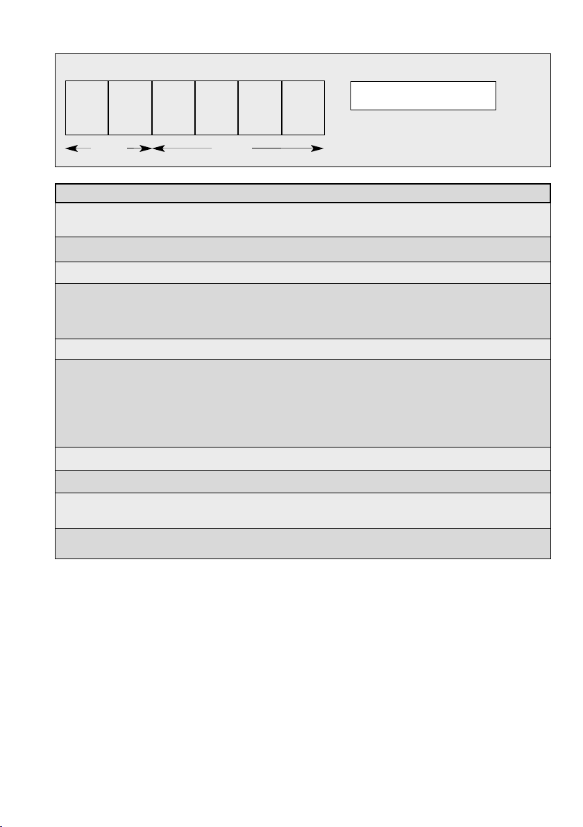
1 Alternate two-tone 800 - 1000 0.5 1 1 1 1 1 Fire Alarms
2 Alternate two-tone 2500 - 3100 0.5 0 1 1 1 1 Security Alarms
3 Alternate fast two-tone 800 - 1000 0.25 1 0 1 1 1 Increased urgency
4 Alternate fast two-tone 2500 - 3100 0.25 0 0 1 1 1 Security deterrent
5 Alternate two-tone 440 - 554 0.4/0.1 1 1 0 1 1 AFNOR, France
6 Alternate two-tone 430 - 470 1.0 0 1 0 1 1
7 Alternate v. fast two-tone 800 - 1000 0.13 1 0 0 1 1
8 Alternate v. fast two-tone 2500 - 3200 0.07 0 0 0 1 1
9 Alternate two-tone 440 - 554 2.0 1 1 1 0 1 Turn-out, Sweden
10 Continuous tone 700 - 0 1 1 0 1 All-clear, Sweden
11 Continuous tone 1000 - 1 0 1 0 1
12 Continuous tone 1000 - 0 0 1 0 1
13 Continuous tone 2300 - 1 1 0 0 1
14 Continuous tone 440 - 0 1 0 0 1
15 Interrupted tone 1000 2.0 1 0 0 0 1
16 Interrupted tone 420 1.25 0 0 0 0 1 AS2220, Australia
17 Interrupted tone 1000 0.5 1 1 1 1 0
18 Interrupted tone 2500 0.25 0 1 1 1 0
19 Interrupted tone 2500 0.5 1 0 1 1 0
20 Interrupted tone 700 6/12 0 0 1 1 0 Pre-vital mess, Sweden
21 Interrupted tone 1000 1.0 1 1 0 1 0
22 Interrupted tone 700 4.0 0 1 0 1 0 Air-raid, Sweden
23 Interrupted tone 700 0.25 1 0 0 1 0 Local warning, Sweden
24 Interrupted tone 720 0.7/0.3 0 0 0 1 0 Industrial alarm, Germany
25 Int. fast rising volume 1400 0.25 1 1 1 0 0
26 Fast siren 250 - 1200 0.085 0 1 1 0 0
27 Rising constant, fall 1000 10/40/10 1 0 1 0 0 Industrial alarm, Germany
28 ISO 8201 Evacuation 800 - 1000 as std 0 0 1 0 0 Int. evacuation alarm
29 Fast whoop 500 - 1000 0.15 1 1 0 0 0
30 Slow whoop 500 - 1200 4.5 0 1 0 0 0 Evacuation, The Netherlands
31 Reverse sweep 1200 - 500 1 1 0 0 0 0 Evacuation, Germany
32 Siren 500 - 1200 3.0 0 0 0 0 0
Switch settings: ON=1 und OFF=0
First and Sec nd Stage Frequency / Rept. Switches Special
Hz rate 1 2 3 4 5 Applicati n
The PFEER sound signals recommended by UKOOA are:
General Alarm Sound signal 15 Interrupted tone 1000 Hz
PAPA Sound signal l 31 Reverse Sweep 1200 - 500 Hz
Toxic gas Sound signal 11 Continuous tone 1000 Hz
Warning: Very loud alarm sound, 120 dB(A) output. Wear
ear defenders when testing, installing and commissioning.
High Voltages are present within the beacon when
operational.
Sund selecti n table
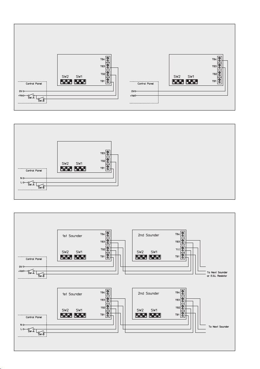
Note: Third wire is needed at TB3
for second stage alarm.
DC Input second stage with third wire
Line integrity: monitor via reverse polarity
DC Input second stage by supply reversal
Line integrity: monitor via threshold (applied voltage ≤ 1 V)
An end-of-line (E.O.L) resistor is required for line monitoring and
it should be a minimum resistance of 3K3 ohms and 0.5 watts.
AC Input
System connection
4
Figure 1
Figure 3
Figure 4
Figure 2
Warning: high voltages are present
within the beacon when operational
Wiring details for XL units (opt. /acoust. combination)
User inf rmati n
1. The appliance has been designed for insulation class I and is only to be connected to, and operated with, the specified
voltage. Specifications of polarity must be observed.
2. Ensure that the casing is not damaged.
3. The relevant codes of Practice an Trade Association requirements for save operation must be observed.
4. Live components may be come exposed when covers are opened or parts are removed. Before opening the appliance
for alignment, maintenance, repair or replacement of parts, the appliance must be disconnected from all power sup-
plies. If it is necessary to carry out alignment, maintenance or repair on the open and live device, this is only to be
undertaken by a qualified specialist who has received corres ponding instruction.
5. Capacitors may still be in a charged state even after the appliance has been disconnected from all power supplies.
6. The appliance is only to be operated under the specified ambient conditions and in the specified mode of operation.
Unfavou rable ambient conditions may cause damage to the appliance and put the user’s life at risk. Unfavou rable
ambient conditions may be:
• excessive air humidity (>75%, relative, condensing)
• moisture, dust (observe protection class)
• flammable gases, vapours, solvents
• excessively high ambient temperatures (>55 C)
7. The ambient temperatures must be within the specified range.
8. The appliance is designed for both indoor and outdoor use.
9. The installation and commissioning of the appliance may only be carried out by a qua lified specialist; the same applies
to any repairs with original spare parts. The use of other than original spare parts may cause damage or injury.
10. The AXL08 has a very intense lighting strength. In order to avoid damage to eyesight, please refrain from looking at
the lamp for any length of time when it is in operation.
5
Figure 5

FHF Funke + Huster Fernsig GmbH
Gewerbeallee 15-19 · D-45478 Mülheim an der Ruhr
Phone +49 / 208 / 82 68-0 · Fax +49 / 208 / 82 68-286
http://www.fhf.de · e-mail: [email protected]
Subject to alterations or errors
This manual suits for next models
1
Table of contents
Other FHF Marine Equipment manuals


Popular Marine Equipment manuals by other brands


Federal Signal Corporation
Federal Signal Corporation G-SND instruction manual

Hawkeye Mfg
Hawkeye Mfg DF1000D Installation and operation manual

marinco
marinco MiniVent 1000 installation instructions

Global Fire Equipment
Global Fire Equipment VALKYRIE AS IP65 quick start guide

DAVIS
DAVIS Vantage Vue PRO+ installation guide

Simrad
Simrad ITI datasheet