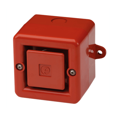
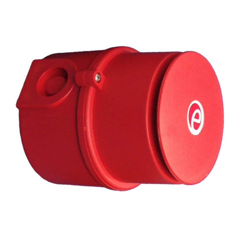
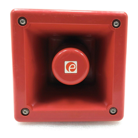
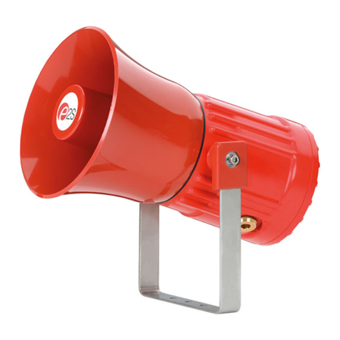
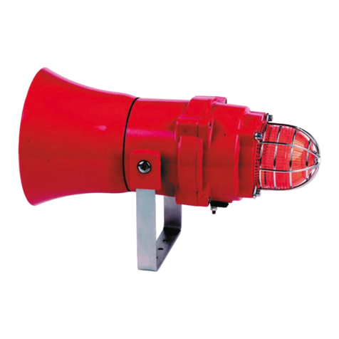
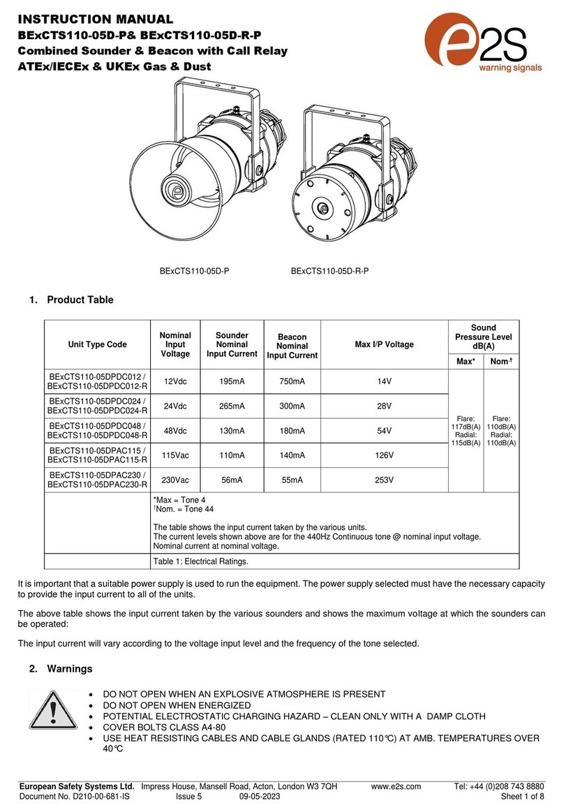
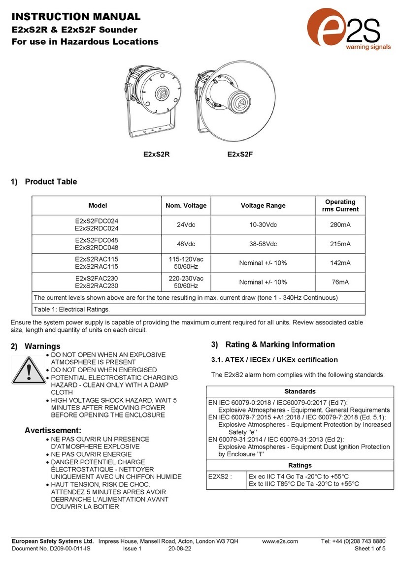
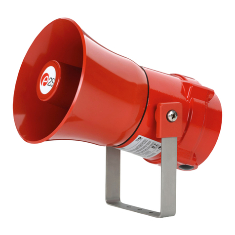
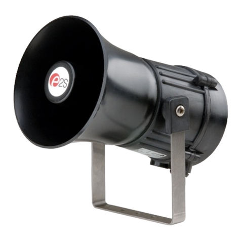
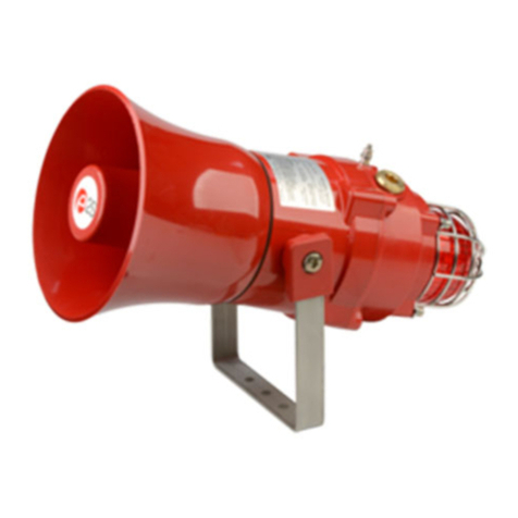
E2S BE DCS110-05D Series User manual

_______________________________________________________________________________________________________________________________
European SafetySystemsLtd. Impress House, MansellRoad, Acton, London W37QHsales@e-2-s.com Tel: +44 (0)208 743 8880
www.e-2-s.com Fax: +44 (0)208 740 4200
DocumentNo. IS2463-PIssue E19-03-10 Sheet 1of6
INSTRUCTIONMANUAL(ATEX/IECEx)
BExDCS110-05D
FlameproofCombined Sounder/Beacon
ForuseinFlammableGas and DustAtmospheres
1)Introduction
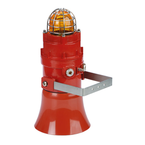
TheBExDCS110-05Disflameproofcombinedsounder/
beaconwhichiscertifiedtomeettherequirementsofthe
ATEX directive94/9/EC andtheIECExscheme. Thesounder
sectionproducesloudaudiowarningsignalsandthebeacon
sectionproducesasynchronised visualwarningsignal. The
unit canbe usedinhazardousareaswherepotentially
flammablegasanddustatmospheresmay bepresent.
Thirty-twodifferentfirststage audioalarmsoundscan be
selected byinternalswitches, andeachonecan be externally
changed toasecondorthirdstagealarmsound(seetone
tableon Page5). Thesounderproducesoutputlevelsinthe
110dB(A)range andthebeaconhasaflashenergyof5
joules. Theunit canbe used inZone1andZone2areaswith
gasesingroupsIIAandIIBandwithTemperature
Classificationsof T1, T2, T3andT4andcan also beusedin
Zone21andZone22 areas forcombustibledustsandhas
an IPratingofIP67andasurfacetemperatureratingof
T115ºCbasedonaTamax. of70ºC(T100ºCat +55ºC).
2)Marking
All unitshavearatinglabel, whichcarries thefollowing
important information:-
UnitType No. BExDCS110-05D
Input Voltage: DC Units12Vor 24Vor 48V
AC Units230Vor 115V
Codes: ExdIIBT4 for Ta–50°Cto+70ºC
ExtDA21IP6XT115°Cbased onmax Taof+70°C
CertificateNo. KEMA01ATEX2223X
IECExKEM10.0025X
“Warnings” DONOTOPENWHENANEXPLOSIVE
GAS / DUSTATMOSPHEREISPESENT
COVERBOLTSCLASS A4-80
USE HEATRESISTINGCABLES AND
CABLEGLANDS (Rated 110ºC) AT
AMB. TEMPERATURES OVER40ºC
Year ofConstruction/
Serial No. i.e. 10 / 1DCS21000001
3) TypeApprovalStandards
TheunitshaveanEC Type examinationcertificateissuedby
KEMAandhavebeenapproved tothefollowingstandards:-
EN60079-0:2006 IEC60079-0:2004(Ed4) General Requirements
EN60079-1:2007 IEC60079-1:2007 (Ed6) Flameproof Enclosure‘d’
EN61241-0:2006 IEC61241-0:2004(Ed1) DustGeneral
Requirements
EN61241-1:2004 IEC60079-1:2004(Ed1) DustEnclosures tD
4) Installation Requirements
Theunit mustbe installed inaccordancewiththelatest
issuesoftherelevantpartsofthe EN60079specifications or
theequivalentIEC specifications–Selection,Installationand
maintenance ofelectricalapparatusforuse inpotentially
explosiveatmospheres(otherthanminingapplicationsor
explosiveprocessingandmanufacture):-
EN60079-14:2008 ElectricalInstallations inHazardous
IEC60079-14:2007 (Ed4)Areas (other than mines)
EN60079-10:2003 Classification of Hazardous Areas
IEC60079-10:2008 (Ed1)
Theinstallationoftheunit mustalso beinaccordance with
any localcodesthatmayapplyandshouldonlybe carried
outbyacompetentelectricalengineerwhohasthe
necessarytraining.
5) Zones,Gas Group, Category,IPRating and
TemperatureClassification
TheBExDCS110-05Dunit hasbeencertifiedExdIIBT4for
Ta–50°Cto+70ºCforgas andExtDA21IP6XT115ºC
basedonmax.Taof+70ºCfordust. Thismeansthatthe
unitscanbe installed inlocationswiththefollowing
conditions:-
Area Classification Gas:
Zone1Explosivegasairmixturelikelytooccurin
normal operation.
Zone2Explosivegasairmixturenotlikelytooccur,
andifit does, it willonlyexist for ashort time.
GasGroupings:
GroupIIAPropane
GroupIIBEthylene
TemperatureClassification:
T1 400oC
T2 300oC
T3 200oC
T4 135oC
0518
CE Marking:
Notified BodyNo.
II 2G/D
Epsilonx:
Equipment Groupand
Category:

_______________________________________________________________________________________________________________________________
European SafetySystemsLtd. Impress House, MansellRoad, Acton, London W37QHsales@e-2-s.com Tel: +44 (0)208 743 8880
www.e-2-s.com Fax: +44 (0)208 740 4200
DocumentNo. IS2463-PIssue E19-03-10 Sheet 2of6
Area Classification Dust:
Zone21 Explosivedustairmixturelikelytooccurin
normal operation.
Zone22 Explosivedustairmixturenotlikelytooccur,
andifit does, it willonlyexist for ashort time.
IPRating: IP67T100ºCTa< +55ºC
T115ºCTa< +70ºC
Equipment Category: 2G/D
AmbientTemperatureRange: -50°Cto+70°C
6) Location andMounting
Thelocationoftheunit shouldbemadewithdueregardto
theareaoverwhichboththesounderandbeaconwarning
signalmustbeaudibleandvisible.Theunit shouldonlybe
fixed toservicesthat cancarrytheweight oftheunit.
Theunit shouldbesecurelyboltedtoasuitablesurfaceusing
the7mmdiameterboltholesinthestainlesssteelUshaped
mountingbracket(see figure1). Theanglecan thenbe
adjusted inthedirectionsuchthatitswarningsignalscan be
bothheardandseen.Thiscan be achievedbylooseningthe
twolarge bracketscrewsintheside oftheunit, whichallow
adjustmentinstepsof 18°.Oncompletionoftheinstallation
thetwolarge bracketadjustmentscrewsonthesideofthe
unitmustbe fullytightened toensurethattheunitcannot
moveinservice.
SAFETYWARNING:
Theflashdomeguardmustnotberemoved fromthe unit
at anytime.
7) Access to theFlameproofEnclosure
Inordertoconnecttheelectricalsupplycablestothe unit it is
necessarytoremovethebeaconsectiontogainaccess to
theflameproof chamber. To achievethisremovethefourM6
hexagonsocketheadscrews(see figure2)andwithdrawthe
beaconsectiontakingextremecarenottodamagethe
flameproofjointsintheprocess.
Notethefour M6screwsareClass A4-80 stainlesssteel
andonlyscrewsofthiscategorycanbeusedonthese
units. Itisthereforeimportantthatthese screwsandtheir
springwashersarekept inasafeplaceduringinstallation.
Oncompletionofthecablewiringinstallationtheflameproof
jointsshouldbe inspected toensurethattheyareclean and
thattheyhavenotbeendamaged duringinstallation.Also
checkthattheearthbondingwirebetweenthetwocasting
sectionsissecureandthe‘O’ringsealisinplace.When
replacingthebeaconsectioncasting,ensurethatit issquare
withthesoundersectionchambercastingbeforeinserting.
Carefullypushthebeaconsectioninplace allowingtimefor
theairtobe expelled. Onlyafter thebeaconsectioncastingis
fullyinplace shouldthefour M6Stainless Steel A4-80cover
boltsandtheirspringwasherbeinsertedandtightened
down.If thebeaconsectionjamswhileit isbeinginserted,
carefullyremoveit andtryagain.Never use thecover boltsto
force thebeaconsectioncastingintoposition.
Incaseof repair, contactthemanufacturerforinformationon
thedimensionsoftheflameproofjoints.
8) PowerSupplySelection
Itisimportantthatasuitablepowersupplyisusedtorun the
unit. Thepowersupplyselectedmusthavethe necessary
capacitytoprovide theinputcurrenttoall ofthe units
connected tothesystem.Thesounderandbeaconsections
can bothbewired tothesamepowersupplyortodifferent
power supplies
Thefollowingtableshowsthe inputcurrenttakenbythe
soundersectionandbeaconsectionofthevariousunits:-
Unit TypeInput SounderMax.
VoltageCurrentI/PVolts
BExDCS110-05D24VDC 265mA30V
BExDCS110-05D12VDC 195mA15V
BExDCS110-05D48VDC 130mA58V
BExDCS110-05D230VAC56mA264V
BExDCS110-05D115VAC110mA126V
Unit TypeInput BeaconMax.
VoltageCurrentI/PVolts
BExDCS110-05D24VDC 300mA30V
BExDCS110-05D12VDC 750mA15V
BExDCS110-05D48VDC 1800mA58V
BExDCS110-05D230VAC55mA264V
BExDCS110-05D115VAC140mA126V
Theabovetablealsoshowsthe maximumvoltagesatwhich
theunitscan be operated.
SounderSection
Theinput currenttothesounder sectionwill varyaccordingto
thevoltage input level andthefrequencyofthetoneselected.
Thecurrentlevelsshownaboveareforthe440Hz
Continuoustone@nominalinputvoltage.The24Vand48V
S/SMounting
Bracket
Sounder
Section
Flashdome
Guard
Fig1
Beacon
Section
4off Cover Screws ExternalEarth
Terminal
Fig2
PlasticAcousticHorn
(Anti-staticPlastic)

_______________________________________________________________________________________________________________________________
European SafetySystemsLtd. Impress House, MansellRoad, Acton, London W37QHsales@e-2-s.com Tel: +44 (0)208 743 8880
www.e-2-s.com Fax: +44 (0)208 740 4200
DocumentNo. IS2463-PIssue E19-03-10 Sheet 3of6
DC unitsandthe230VAC,115VAC unitshaveaswitching
voltage regulatorcircuit andthereforetheinputcurrentlevel
will decreaseslightlyastheinputvoltage inincreasedand
will increase slightlyastheinputvoltage isreduced.The12V
unitsdo nothaveavoltage regulatorandthereforetheirinput
current will increase whentheinputvoltage isincreased.
BeaconSection
Theinputcurrenttothebeaconsectionwill varyaccordingto
thevoltage inputlevel. Thecurrentlevelsshownaboveare
fornominalinputvoltage.The12V,24Vand48VDCunits
haveaconvertercircuit andthereforetheinputcurrentlevel
will decreaseslightlyastheinputvoltage inincreasedand
will increase slightlyastheinput voltage isreduced.
9) CableSelection
Whenselectingthecablesizeconsiderationmustbegivento
theinputcurrentthateachunit draws(see tableabove), the
numberofunitsonthelineandthelengthofthecableruns.
Thecablesizeselectedmusthavethenecessarycapacityto
provide theinputcurrenttoall oftheunitsconnectedtothe
line.
SAFETYWARNING: Iftheunit isusedathighambient
temperatures,i.e.over+40ºC,thenthecableentry
temperaturemay exceed +70ºCandthereforesuitableheat
resistingcables mustbeused,witharated service
temperatureofat least 110ºC.
10) Earthing
BothAC andDC unitsmustbeconnectedtoagood quality
earth.Theunitsareprovidedwithinternalandexternal
earthingterminals,whichareboth,locatedonthe beacon
sectionoftheunit (see figures2and3).
Whenusingtheinternalearthterminalensurethatthe
stainless steelM4flatwasherisbetweentheincoming earth
wireandtheenclosure.
Whenusingtheexternalearthterminalacablecrimplug
mustbe used.Thecablelugshouldbe locatedbetweenthe
twoM5stainless steelflatwashers.TheM5stainlesssteel
springwashermustbe fixed betweentheouterflatwasher
andtheM5stainless steelnuttoensurethatthecablelugis
secured against looseningandtwisting.
Theinternalearthbondingwireensuresthatagoodquality
earthismaintained betweenthesoundersectioncastingand
thebeaconsectioncasting.
11) CableGlands
TheBExDCS110-05Dunit hasdual cableglandentries which
haveanM20 x1.5entrythreadasstandard.Onlycable
glands approvedforEx‘d’applicationscan be used,which
mustbe suitableforthetype ofcablebeingusedandalso
meettherequirementsoftheEx‘d’flameproofinstallation
standardEN60079-14:2008/ IEC60079-14:2007.
Whenonlyonecableentryisusedtheotheronemustbe
closedwithanEx‘d’ flameproofblankingplug, whichmust be
suitablyapproved for theinstallationrequirements.
For combustibledustapplications,thecableentrydevice and
blankingelementsshall be intype ofexplosionprotection
increasedsafety"e"orflameproofenclosure"d"andshall
haveanIP6XratingaccordingtoEN60529:1992.
SAFETYWARNING: Iftheunit isusedathighambient
temperatures,i.e.over+40ºC,thenthecableentry
temperaturemay exceed +70ºCandthereforesuitableheat
resistingcableglandsmustbe used,witharated service
temperatureofat least 110ºC.
12) CableConnections
Thecombinedsounderbeaconunit BExDCS110-05Dhas
separateprinted circuit boardsinthesounderandbeacon
sections.Theterminalsforthesounderareontheprinted
circuit boardinthesoundersectionandtheterminalsforthe
beaconareontheprinted circuit boardinthebeaconsection
(seefigures 4&5and6&7). Seesection7ofthismanualfor
accesstotheenclosureandthewiringdiagramsattheendof
thismanual.
Thesounderandbeaconsectionscan be wiredtothesame
inputsupplysothattheyoperatesimultaneouslyortheycan
be wiredtoseparateinputsuppliessotheycan beoperated
independently(seediagramsofpages 5and6ofthis
manual). If thesounderandbeaconsectionsareconnected
tothesameinputsupply,theincomingcablesshouldbe
connected totheinput terminalsonthebeaconboardandthe
twoconnectingwires,thataresuppliedwiththeunit,should
beusedtolink thesupplyfromtheinterconnectingterminals
onthebeaconboarddowntothesupplyterminalsonthe
sounderboard.
SOUNDER SECTIONCONECTIONS
OntheACunitsatwo-way terminalblockisprovidedforthe
liveandneutral mainssupplywires andathree way terminal
blockisprovidedforlinkingthesecond andthirdstages,(see
figure7). OntheDC unitsafourwayterminalblockis
providedfor+veand–vesupplyinputandsecondandthird
stage modesofoperation, (see figure6).
Asinglewirewithacross sectionalareaofupto4mm²can
be connectedtoeachterminalwayorifan inputandoutput
wireisrequired two2.5mm²wires can be connected toeach
terminalway.Whenconnectingwires totheterminalsgreat
careshouldbetakentodress thewireso thatwhenthe
beaconsectionisinserted intothechamberthewires do not
exert excess pressureontheterminalblocks.Thisis
particularlyimportantwhenusingcables withlarge cross
InternalBonding Wire Terminal
InternalEarthTerminal
2off M20
CableEntries
Figure3

_______________________________________________________________________________________________________________________________
European SafetySystemsLtd. Impress House, MansellRoad, Acton, London W37QHsales@e-2-s.com Tel: +44 (0)208 743 8880
www.e-2-s.com Fax: +44 (0)208 740 4200
DocumentNo. IS2463-PIssue E19-03-10 Sheet 4of6
sectionalareassuchas2.5mm²andabove.If thesounderis
wired tothesamepowersupplyasthebeaconalwaysuse
theflexibleinterconnectingwires provided.
BEACONSECTIONCONNECTIONS
Thecableconnectionsaremade intotheterminalblockson
theelectronicpcbassemblylocatedinthebeaconsection
enclosure.Afour-wayterminalblockisprovidedonbothAC
andDC beacons.Thereforetherearetwoliveterminalsand
twoneutralterminalsfortheinputandoutputwiringonAC
units.OntheDC unitstherearetwo+veterminalsandtwo-
veterminalsfor theinput andoutputwiring.
Wireshavingacross sectionalarea ofupto4mm²can be
connected toeachterminalway.Whenconnectingwires to
theterminalsgreat careshouldbe takentodress thewires so
thatwires do notexert excesspressureontheterminal
blocks.Thisisparticularlyimportantwhenusingcables with
large cross sectional areassuchas2.5mm² andabove.
13) ToneSelection and 2nd and 3rd StageAlarms
TheBExDCS110-05Dsounder sectionhas32differenttones
thatcan be selectedforthefirststagealarm.Thesounders
can thenbe switched tosoundsecondandthirdstage alarm
tones. Thetones areselectedbyoperationofaDIPswitchon
thesounderpcb forbothDCandACunits.Thetonetableon
page fiveshowstheswitchpositionsforthe32 tones and
whichtones areavailableforthesecondandthirdstages. To
operatethesounderonstage onesimplyconnectthesupply
voltage tothenormalsupplyterminals(+veand–veforDC
units, LandNfor AC units).
Theoperationofthesecondandthirdstages isdifferentfor
DC andAC units.
DC UnitsSecondandThirdStage ToneSelection
TheBExDCS110-05DDCsoundersectionhasthefacilityto
use either+veor–veswitchingtochange thetonetothe
secondandthirdstages.For–veswitchingconnectthetwo
headersonthepcbtotheleft-hand(marked –ve)andcentre
pins.For+veswitchingconnecttheheaderstotherighthand
(marked +ve)andthecentrepins.To change tothesecond
stage tone, connecteithera-veor+ve supplylinetoterminal
S2,dependingonwhichswitchingmodeisbeingusedwhile
maintainingthedc supplytothe+veand–veterminals.
Similarlyforthethirdstage tone,connecta-veor+vesupply
linetoterminalS3.ThesupplytotheS3terminalwill
automaticallyoverride asupplytotheS2terminal.
AC UnitsSecondandThirdStageToneSelection
To selectthesecondandthirdstage tones onthe
BExDCS110-05DACsoundersection,theCommon(C)
terminalonthethree way terminalblockonthepcbis
connected totheS2terminalforthesecondstage toneand
theS3terminal for thethirdstage tone.
14) Volume Control
TheBExDCS110-05Dsoundersection,withtheexceptionof
12VDCunits,hasavolumecontroltoadjustthe outputlevel.
Figure7
Figure6
BExDCS110-05DDCSounder Section
BExDCS110-05DACSounder Section
VolumeControl
DIPSwitch
DIPSwitch
VolumeControl
DC Input
Terminals
Stage Headers
Stage Terminals
A
CInput
Terminals
S2
S3
-
+
S2
S3
C
N
L
L
L
N
N
Figure4
ACInput
Terminals
Interconnecting Terminalsto
sounderpcb(simultaneous
mode of operation)
BExDCS110-05DACBeaconSection
Flip / Flop
Pin Header
DC Input
Terminals
Figure5
-
-
+
+
Flip / Flop
Pin Header
BExDCS110-05DDCBeaconSection
Interconnecting Terminalsto
sounderpcb(simultaneous
mode of operation)

_______________________________________________________________________________________________________________________________
European SafetySystemsLtd. Impress House, MansellRoad, Acton, London W37QHsales@e-2-s.com Tel: +44 (0)208 743 8880
www.e-2-s.com Fax: +44 (0)208 740 4200
DocumentNo. IS2463-PIssue E19-03-10 Sheet 5of6
To settherequired outputlevel, adjustthepotentiometeron
thepcb.Formaximumoutputlevelthepotentiometershould
be set tothefullyclockwise position.
15) End ofLineMonitoring (DC Units)
OnBExDCS110-05DDC units,dc reverselinemonitoring
can beusedifrequired.All DCunitshaveablockingdiode
fittedintheirsupplyinputlines onboththesoundersection
andthebeaconsection. Anendoflinemonitoringdiode or an
endoflinemonitoringresistorcan beconnectedacrossthe
+veand–veterminals.Ifan endoflineresistorisused it
musthaveaminimumresistance valueof3k3ohmsanda
minimumwattage of0.5wattsoraminimumresistancevalue
of500ohmsandamin.wattage of2watts.If thesounder
andbeaconsectionsarewiredtoseparatepowersupplies
thenanendoflinemonitoringcomponentcan be usedin
eachsection.
16) Synchronised Operation
All BExDCS110-05Dunitsthatareconnectedtothesame
supplylinewill haveasynchronized soundoutputanda
synchronisedflashrateatoneflasheverysecond. To ensure
thattheunitswill be synchronisedcheckthatthepinheader
isnotfitted,i.e.thetwoheaderpinsarenotshorted together
(seeFigures4and5).
17) Flip / Flop Operation
Twounitscan be mounted close toeachothertoformaflip-
flopoperation,wherethebeaconswill flashalternately.To
achievethismodeofoperation,fit apinheadertotheflip-
flopheaderpinsontheelectronics board,i.e.thetwoheader
pinsareshortedtogether, (seefigures4and5) onone of the
twobeacons.Thefirstflashonthebeaconthathasthe
headerfittedwill be delayedby½second.Thetwobeacons
will thenflashalternatelyevery½asecond.
TONESELECTIONTABLE NoteSwitch No. 6isnotused
ToneSelection
DIPSwitch
Settings
StageSelection
Stage1FrequencyDescription 12345
Stage2Stage3
1Continuous1000Hz
Toxicgasalarm
00000Tone31 Tone11
2Alternating800/1000Hzat0.25s
intervals
10000Tone17 Tone5
3SlowWhoop 500/1200Hzat0.3Hz
with0.5sgaprepeated
01000Tone2Tone5
4Sweeping800/1000 at1Hz11000Tone6Tone5
5Continuousat2400Hz00100Tone3Tone27
6Sweeping2400/2900Hzat7Hz10100Tone7Tone5
7Sweeping2400/2900Hzat1Hz01100Tone10 Tone5
8Siren500/1200/500Hzat0.3Hz11100Tone2Tone5
9Sawtooth1200/500Hzat1Hz00010Tone15 Tone2
10 Alternating2400/2900Hzat2Hz10010Tone7Tone5
11 Intermittent1000Hzat0.5Hz
Generalalarm
01010Tone31 Tone1
12 Alternating800/1000Hzat0.875Hz11010Tone4Tone5
13 Intermittent2400Hzat1Hz00110Tone15 Tone5
14 Intermittent800Hz0.25son 1soff 10110Tone4Tone5
15 Continuousat800Hz01110Tone2Tone5
16 Intermittent660Hz150mSon,
150mSoff
11110Tone18 Tone5
17 Alternating544Hz
(100mS)/440Hz(400mS)
00001Tone2Tone27
18 Intermittent660Hz1.8son, 1.8soff 10001Tone2Tone5
19 1400Hzto1600Hzsweepupover
1s-1600Hzto1400Hzsweepdown
over 0.5s
01001Tone2Tone5
20 Continuous660Hz11001Tone2Tone5
21 Alternating554/440Hzat1Hz00101Tone2Tone5
22 Intermittent554Hzat0.875Hz10101Tone2Tone5
23 800Hzpulsingat2Hz01101Tone6Tone5
24 Sweeping800/1000Hzat50Hz11101Tone29 Tone5
25 Sweeping2400/2900Hzat50Hz00011Tone29 Tone5
26 Simulatedbell sound 10011Tone2Tone1
27 Continuous554Hz01011Tone26 Tone5
28 Continuous440Hz11011Tone2Tone5
29 Sweeping800/1000Hzat7Hz00111Tone7Tone5
30 420Hzrepeating0.625son, 0.625s
off Australianalertsignal
10111Tone32 Tone5
31 1200/500Hzat1Hz
Preparetoabandonplatform
01111Tone11 Tone1
32 Sweeping500/1200Hz3.75son,
0.25soff 15Hz
11111Tone26 Tone1
Unit No.2
+
+
-
S2
S3
-
Sounder
PCB
+ -S2 S3
Unit No. 1
Beacon
PCB
+- +-
Beacon
PCB
Beacon
PCB
+-
Sounder
PCB
+ -S2 S3
Sounder
PCB
+ -S2 S3
Unit No.3
BEx
D
CS110
-
05DDC CombinedSounderUnit
BeaconandSounderWiredfor Independent Operation
NOTE
Eitherthe+veorthe-vewiremay
bemadecommontoboththe
sounderand thebeacontoreduce
thenumberof coresinthecable.

_______________________________________________________________________________________________________________________________
European SafetySystemsLtd. Impress House, MansellRoad, Acton, London W37QHsales@e-2-s.com Tel: +44 (0)208 743 8880
www.e-2-s.com Fax: +44 (0)208 740 4200
DocumentNo. IS2463-PIssue E19-03-10 Sheet 6of6
UnitNo.2
+
-
Sounder
PCB
+-S2 S3
Unit No. 1
Beacon
PCB
+- -
+
-
+-
Beacon
PCB +
+-
Beacon
PCB
+-S2 S3
Sounder
PCB
+-S2 S3
Sounder
PCB
-
+
Unit No.3
S2
S3
Unit No.2
L
C
N
L
N
LNC S2 S3
Sounder
PCB
Unit No. 1
LN
Beacon
PCB
LN
Beacon
PCB
LN
Beacon
PCB
LNC S2 S3
Sounder
PCB
LNC S2 S3
Sounder
PCB
Unit No. 3
Unit No.2
C
N
S3
S2
L
Sounder
PCB
Unit No.1
LNC S2 S3
Beacon
PCB
LN
L
NLN
Beacon
PCB L
N
Beacon
PCB
LN
Sounder
PCB
LNC S2 S3 LNC S2 S3
L
N
Sounder
PCB
UnitNo.3
BEx
D
CS110
-
05DDC CombinedSounderUnit
BeaconandSounderWiredfor SimultaneousOperation
BEx
D
CS110
-
05DACCombinedSounderUnit
BeaconandSounderWiredfor Independent Operation
BEx
D
CS110
-
05DACCombi
nedSounderUnit
BeaconandSounderWiredfor SimultaneousOperation
NOTE
EithertheLortheNwiremaybe
madecommontoboththesounder
and thebeacontoreducethe
numberof coresinthecable.

EC DECLARATION OF CONFORMITY
Manufacturer: European Safety Systems Ltd.
Impress House, Mansell Road, Acton
London, W3 7QH, UK
Telephone: +44 (0)20 8743 8880 European Safety Systems Ltd
Facsimile: +44 (0)20 8740 4200 Company Registration No. 2763350
E-mail: sales@e2s.com Registered Office: Impress House
www.e2s.com Mansell Road, London, UK, W3 7QH, UK
Equipment Type: BExCS110-05D, BExDCS110-05D,
BExCL15-05D, BExDCL15-05D,
BExCA110-05D, BExDCA110-05D,
BExCTS110-05D, BExDCTS110-05D,
BExCTV110-05D, BExDCTV110-05D
BExCS110L1D, BExDCS110L1D
Directive 94/9/EC: Electrical and Mechanical equipment for use in explosive atmospheres (ATEX)
Notified Body for EC type Examination:
KEMA Quality B.V.
Notified Body No.: 0344
Utrechtseweg 310, 6812 AR Arnhem, The Netherlands
EC
-
type Examination Certificate:
KEMA 01ATEX2223X
Notified Body for Quality Assurance Notification:
Sira Certification Service
Notified Body No.: 0518
Rake Lane, Eccleston, Chester CH4 9JN, UK
Quality Assur
ance Notification
:
SIRA 05 ATEX M342
Provisions fulfilled by the equipment:
ll2 G Ex d llB T4
ll 2 D Ex tD A21 IPGX T100 °C or T115 °C
Standards applied:
EN 60079-0:2006
EN 60079-1:2007
EN 61241-0:2006
EN61241-1:2004
Directive 2004/108/EC: Electromagnetic Compatibility Directive (EMC)
Standards applied:
EN 61000-6-1:2007
EN 61000-6-2:2005
EN 61000-6-3:2007
EN 61000-6-4:2007
The standards EN 60079-0: 2006, EN 61241-0:2006 and EN 61241-1:2004 are no longer harmonized. The requirements
of these standards have been checked against the harmonized standards EN 60079-0:2009 and EN 60079-31:2009 and
there were no major technical changes affecting the latest technical knowledge for the products listed above.
On behalf of European Safety Systems Ltd., I declare that, on the date the equipment accompanied by this declaration is
placed on the market, the equipment conforms with all technical and regulatory requirements of the above listed
directives.
Martin Streetz Date and Place of Issue: London, 04/07/2012
Quality Assurance Manager Document No: DC-005-Issue_C
Table of contents
Other E2S Marine Equipment manuals

E2S
E2S BExDCTS110-05D User manual

E2S
E2S GNExS2 User manual

E2S
E2S DL105H AlertAlight User manual

E2S
E2S STExC1 User manual

E2S
E2S D1xS2FDC024-A User manual

E2S
E2S Minialarm IS-MA1-R User manual

E2S
E2S D2xS2F Series User manual

E2S
E2S GNExS2 User manual

E2S
E2S BEXCS11005D230AC-AM User manual

E2S
E2S AlertAlight AL121H User manual
Popular Marine Equipment manuals by other brands

ESP
ESP MAGPRO-WS Installation instruction

Francis
Francis A7183 VX500 150w 115/230v Xenon User instruction & installation manual

Blue Sea
Blue Sea 8410 instructions

NorthStar
NorthStar 8000I 1KW NETWORK SOUNDER installation manual

Furuno
Furuno Color LCD Sounder FCV-620/585 Operator's manual

GST
GST C-9404(Ex) quick start guide