FHF 5843/2 User manual

Akustischer Anrufmelder / Acoustic Secondary Sounder
FHF BA 5843-2 09/02
Typ 5843/2
Hinweis
Vor Installation des Gerätes ist
diese Gebrauchssanleitung sorg-
fältig zu lesen. Bei eventuellen
Schäden und Ansprüchen gelten
die „Allgemeinen Lieferbedingun-
gen für Erzeugnisse und Leistun-
gen der Elektroindustrie“ in ihrer
jeweils letzten Fassung.
Verwendungshinweise
Der akustische Anrufmelder ist für
den Einsatz im allgemeinen Indus-
triebereich und Wohnbereich kon-
struiert und erlaubt das Betreiben
in Gebäuden und im Freien.
Das Gerät wird mit einem Telefon
(mit W-Ader-Anschluss) zusammen-
geschaltet um aus der Rufwechsel-
spannung ein weiteres Rufsignal
entfernt vom Telefon zu erzeugen.
Montage
Das Gerät ist für die Wand- und
Deckenmontage (Beachte: Tech-
nische Daten) geeignet. Die An-
baumaße sind dem Maßbild zu
entnehmen. Befestigungselemente
und Untergrund müssen das
Gewicht des Gerätes (~0,9 kg)
tragen können.
Anschließen und Einstellen
Das Anschließen und Einstellen
des Gerätes darf nur durch unter-
wiesenes Fachpersonal erfolgen.
Es sind die Vorschriften und Hin-
weise des jeweiligen Landes zum
Anschalten an das öffentliche Tele-
fonnetz bzw. an private Neben-
stellenanlagen zu beachten. Der
Zweitwecker ist für den Betrieb an
Telefonen mit W-Ader vorgesehen.
Nachfolgende Anschluss- und Ein-
stellvorschriften sind einzuhalten:
Telefonanschluss an Klemmen W,
Lb, Schutzerde PE am Gehäuse.
Gem. VDE0804 Teil 100
(EN41003:05.1994) gelten Tele-
kommunikationseinrichtungen als
elektrisch sicher. Die Verwendung
der Schutzerde muss der Errichter
gem. seiner Anlagenkonfiguration
individuell entscheiden.
Note
Prior to installing the device, these
operating instructions must be
read carefully. In case of any
damage and liabilities the latest
version of the „General terms of
delivery of products and services
in the electric industry“ is authori-
tative.
Notes on use
The secondary sounder is designed
for use in general industrial areas
and for domestic use, and may be
used both indoors and outdoors.
The device must be connected
with a telephone (with a W con-
ductor) to use the ringing alterna-
ting current to generate a further
ringing signal away from the tele-
phone.
Mounting
The device is suited for wall and
ceiling mounting (observe the
Technical specifications). Refer to
the dimensional drawing for the
mounting dimensions. Both the
fasteners and the mounting surface
must be able to carry the weight
of the device (~0,9 kg).
Connecting and Setting
Only especially educated person-
nel may connect and adjust the
device. The rules and regulations
of each country regarding connec-
tions to the public telephone net-
work or private branch exchanges
must be observed. The secondary
sounder is designed for use with
telephones with a W conductor.
The following regulations regarding
connection and adjustments must
be obeyed: Connect telephone with
terminals W, Lb, Protective Earth
to housing. Telecommunications
installations are regarded as elec-
trically safe according to VDE0804
Part 100 (EN41003:05.1994). The
decision on how to use the Pro-
tective Earth must be taken by the
constructor according to the con-
figuration of the installation.
Abmessungen
Physical dimensions
~137
쏗5,5
M20x1,5
130
150
117
Abmessungen [mm]
Dimensions [mm]
1
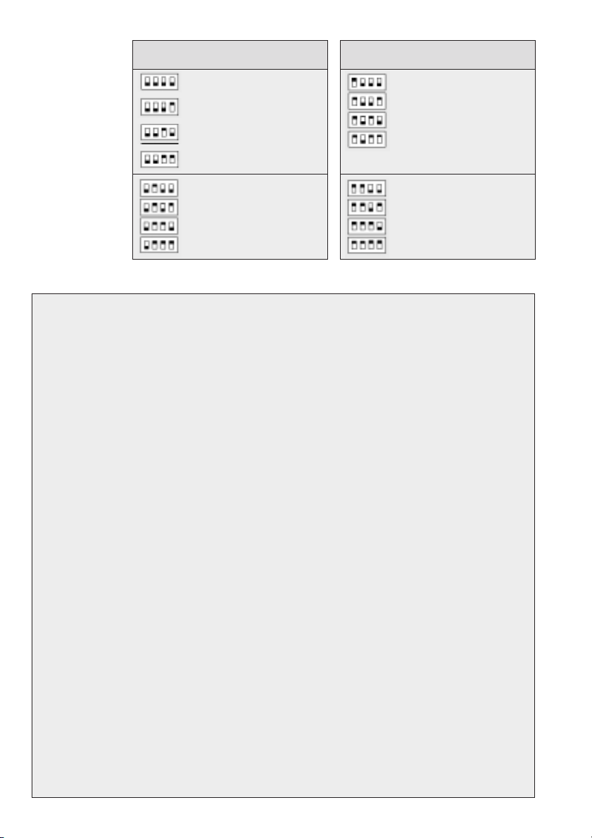
Schalter- Ton- Tonfolge/Ton-
stellung signal folgefrequenz
Dreiton 5 Hz
Dreiton 10 Hz
Dreiton 15 Hz
Dreiton 20 Hz
Zweiton 5 Hz
Zweiton 10 Hz
Zweiton 15 Hz
Zweiton 20 Hz
Technische Daten
Umweltbedingungen:
Betriebstemperatur: -20ºC + 70ºC
Lagertemperatur: -20ºC + 85ºC
Gebrauchslage: Wandmontage, Deckenmontage*
Gehäuseschutzgrad: IP 66 gemäß EN60529
Gehäuseschutzart: I
Telefonanschluss:
Klemmenbezeichnung: W, Lb
Rufwechselspannung: 24 VAC ...75 VAC
Überlagerte Speisespannung: 0 VDC ...63 VDC
Eingangsimpedanz bei 25 Hz: Z ≥8 kΩ
Eingangsimpedanz bei 50 Hz: Z ≥4 kΩ
Akustische Signalisierung:
Akustischer Signalgeber: Lautsprecher
Akustisches Signal: 3-Ton-Ruf,
2-Ton-Ruf,
Einzeltonruf,
Wobbeltonruf
Tonfolgefrequenz: 4 unterschiedliche Einstellungen
über Schiebeschalter wählbar
Lautstärke: ca. 90 dB(A) bei 2-Ton-Ruf,
gemessen in 1m Abstand,
bei einer Rufspannung von 45 VAC und 25 Hz
* In Räumen mit starker Staub- oder Wassereinwirkung sollte möglichst auf Deckenmontage
verzichtet werden.
Einstellen des
Rufsignals Schalter- Ton- Tonfolge/Ton-
stellung signal folgefrequenz
Einzelton 180 ms an
70 ms aus
Einzelton 120 ms an
50 ms aus
Einzelton 60 ms an
25 ms aus
Einzelton Dauerton
Wobbelton 1,8 Hz
Wobbelton 3,6 Hz
Wobbelton 3,9 Hz
Wobbelton 7,8 Hz
2

Technical specification
Ambient conditions:
Operating temperature: -20ºC + 70ºC
Storage temperature: -20ºC + 85ºC
Operating position: Wall mount, ceiling mount*
Protection category: IP 66 according to EN60529
Insulation class: I
Telephone connection:
Terminals: W, Lb
Ringing alternating current: 24 VAC ...75 VAC
Overlaid supply voltage: 0 VDC ...63 VDC
Input impedance at 25 Hz: Z 욷8 k액
Input impedance at 50 Hz: Z 욷4 k액
Acoustic signalling:
Acoustic signalling device: Loudspeaker
Acoustic signal: 3-tone call
2-tone call
single tone call
warble tone call
Tone sequence: Choice of 4 different
DIP-switch settings
Sound pressure level: approx. 90 dB(A) using 2-tone call,
at 1 m distance and a ringing
alternating current of 45 VAC
and a frequency of 25 Hz
* If possible, avoid ceiling mounting in rooms considerably influenced by dust or water
Setting
the tone signal
Switch- Signals Tone sequence
position
Tone seq. frequency
Three-tone 5 Hz
Three-tone 10 Hz
Three-tone 15 Hz
Three-tone 20 Hz
Two-tone 5 Hz
Two-tone 10 Hz
Two-tone 15 Hz
Two-tone 20 Hz
Switch- Signals Tone sequence
position
Tone seq. frequency
Single tone 180 ms on
70 ms off
Single tone 120 ms on
50 ms off
Single tone 60 ms on
25 ms off
Single tone Continuous
tone
Warble tone 1.8 Hz
Warble tone 3.6 Hz
Warble tone 3.9 Hz
Warble tone 7.8 Hz
3

Änderungen vorbehalten
Subject to change without notice
FHF Funke + Huster Fernsig GmbH
Eintrachtstrasse 95
D-42551 Velbert Phone +49 / 20 51 / 270-0
Fax +49 / 20 51 / 270-377 http://www.fhf.de
1. The device is designed in compliance with
insulation class I and may be connected and
operated at the mandatory voltage only. A
proper connection must be especially observed.
2. Take care not to damage the housing.
3. The device may be operated under the man-
datory ambient conditions only (refer to Tech-
nical specifications). Bad ambient conditions
may lead to damage to the device.
Such bad ambient conditions are:
• too high continuous air humidity
• inflammable gases, vapours, solvents, dusts
• too low or too high ambient temperatures
4. The mandatory operational position of the
device must be considered.
5. The device is meant for use indoors or out-
doors.
6. During operation of the device the legal and
professional regulations, the safety regulations,
and the electrical rules and regulations regar-
ding operation and connections to private
branch exchanges and the public telephone
network must be observed. Connection and
commissioning may be done by an educated
professional only.
7. The device may be opened by educated pro-
fessional personnel only. During the process
of opening covers or removing parts live parts
may be exposed. If adjusting operations, re-
pairs or a replacement of parts include ope-
ning the device, the device must be separated
from all power sources prior to such work. In
case of repairs only original spare parts may
be used. Any other spare parts may lead to
personal injury and/or equipment damage.
If it is unavoidable to adjust or repair the
powered device, this may be done by an edu-
cated professional only.
8. Continuous subjection to signalling and/or too
small distance to the signalling source may
cause hearing damage.
Benutzerinformation User information
1. Das Gerät ist in Schutzklasse I aufgebaut und
darf nur an der vorgeschriebenen Spannung
angeschlossen und betrieben werden. Es ist auf
einen ordnungsgemäßen Anschluss zu achten.
2. Es ist darauf zu achten, dass das Gehäuse
nicht beschädigt wird.
3. Das Gerät darf nur unter den angegebenen
Umgebungsbedingungen betrieben werden
(siehe Technische Daten). Widrige Umgebungs-
bedingungen können zur Beschädigung des
Gerätes führen.
Solche widrigen Umgebungsbedingungen sind:
• zu hohe kontinuierliche Luftfeuchtigkeit
• brennbare Gase, Dämpfe, Lösungsmittel,
Stäube
• zu niedrige oder zu hohe Umgebungstempe-
raturen
4. Die vorgeschriebene Betriebsgebrauchslage
des Gerätes ist zu berücksichtigen.
5. Das Gerät ist für den Betrieb in Räumen oder
im Freien bestimmt.
6. Bei Betrieb des Gerätes sind die gesetzlichen
und gewerblichen Vorschriften, Unfallverhütungs-
vorschriften sowie elektrische Bestimmungen
und Vorschriften zum Anschluss und Betrieb an
privaten Nebenstellenanlagen und öffentlichen
Fernsprechnetzen zu beachten. Der Anschluss
und die Inbetriebnahme darf nur durch einen
unterwiesenen Fachmann erfolgen.
7. Das Gerät darf nur von unterwiesenem Fach-
personal geöffnet werden. Beim Öffnen von Ab-
deckungen oder Entfernen von Teilen können
spannungsführende Teile freigelegt werden.
Vor einem Abgleich, einer Wartung, einer In-
standsetzung oder einem Austausch von Teilen
muss das Gerät von allen Spannungsquellen
getrennt sein, wenn ein Öffnen des Gerätes
erforderlich ist. Bei eventuellen Reparaturen sind
nur Originalersatzteile zu verwenden. Ab-
weichende Ersatzteile können zu Sach- und/
oder Personenschäden führen.
Wenn ein Abgleichen, eine Wartung oder eine
Reparatur am geöffneten Gerät unter Spannung
unvermeidbar ist, darf das nur durch eine
unterwiesene Fachkraft geschehen.
8. Kontinuierliche Beschallung mit dem Gerät
und/oder zu geringer Abstand von Personen
zur Schallquelle können Gehörschäden verur-
sachen.
Other FHF Marine Equipment manuals


