FHF 5842/2 User manual

1
Ex-Zweitwecker /
Ex-Sec ndary S under
FHF BA 5842-2 03/16
Typ 5842/2
Hinweis
Vor Installation des Gerätes ist diese
Gebrauchsanweisung sorgfältig zu
lesen. Bei eventuellen Schäden und
Ansprüchen gelten die „All ge mei nen
Lieferbedingungen für Erzeugnisse und
Leistungen der Elektroindustrie“ in ihrer
jeweils letzten Fassung.
Verwendungshinweise
Der explosionsgeschützte, Zweitwecker
ist für den Einsatz in ex plosions-
gefährdeten Industrie be reichen, deren
Gebäuden und im Freien, z.B. in der
petroche mischen Industrie, konzipiert.
Die hohe Qua lität der von uns hier ein-
gesetzten und in unserem Labor geprüften
Materialien, gestatten die Verwendung
dieses elek tri schen Betriebsmittels auch
in ex tremen explosionsgefährdeten Be -
reichen der Industrie. Andere Einsatzge-
biete sind mit dem Hersteller abzustimmen.
M ntage
Das Gerät ist für die Wand- und Decken-
montage (Beachte: Tech nische Daten)
geeignet. Die An bau maße sind dem
Maßbild zu ent nehmen.
Befestigungselemente und Untergrund
müssen das Ge wicht des Gerätes
(~ 0,9kg) tragen können.
Anschließen und Einstellen
Anschließen: Das Anschließen und Ein-
stellen des Gerätes darf nur durch un-
terwiesenes Fachpersonal erfolgen.
Das Gerät ist für den Betrieb mit Ruf-
wechselspannung 32 VAC...75 VAC
konstruiert.
Nachfolgende Anschluss- und Einstell-
vorschriften sind einzuhalten: Es sind
die Vorschriften und Hinweise zum An-
schalten an das Telefonnetz zu beach-
ten. Rufwechselspannung an Klemmen
Lb und W.
N te
Prior to installing the device, these
operating instructions must be read
carefully. In case of any damage and
liabilities the latest ver sion of the
„General terms of delivery of products
and services in the electric industry“ is
authoritative.
N tes n use
The explosion proof secondaray son -
der is conceived for use in in dustrial
hazardous areas, in industry buildings
or outdoors, for instance in the petro-
chemical industry. The high quality of
the materials tested in our laboratories
and used in this device enables it to be
used under extreme conditions in the
hazardous areas of industry. Other
areas of use should be discussed with
the manufacturer.
M unting
The device is suited for wall and ceiling
mounting (observe the Technical spe-
cifications). Refer to the dimensional
drawing for the mounting dimensions.
Both the fasteners and the mounting
surface must be able to carry the
weight of the device (~ 0.9 kg).
C nnecting and Setting
Connecting: Only especially educated
personnel may connect and adjust the
device. The device is designed for ope-
ration with Ringing alternating current
32 VAC…75 VAC.
The following connection and adjust-
ment regulations must be obeyed. The
rules and regulations of each country
regarding connections to the public
telephone network must be observed.
Ringing alter na ting current to terminals
Lb and W.
Abmessungen
Physical dimensi ns
~137
쏗5,5
M20x1,5
130
150
117
1
Abmessungen [mm]
Dimensions [mm]
We hereby declare this product is in
compliance with the Essential Health
and Safety Requirements of
ATEX Directive 2014/34/EU,
EMC Directive 2014/30/EU,
Low Voltage Directive 2014/35/EU
and RoHS Directive 2011/65/EU.
The appropriate standards, technical
regulations und specifications you can
take from the attached conformity
declaration and the conformity decla-
rations on our Website.
CE symbol
Wir erklären hiermit, dass sich dieses
Produkt in Übereinstimmung mit den
grundlegenden Sicherheits- und
Gesundheitsanforderungen
der ATEX-Richtlinie 2014/34/EU,
der EMV-Richtlinie 2014/30/EU,
der Niederspannungsrichtlinie 2014/35/EU
und der RoHS-Richtlinie 2011/65/EU
befindet.
Die entsprechenden Normen, techni-
schen Regeln und Spezifikationen
entnehmen Sie bitte der beigefügten
Konformitätserklärung und den Konfor-
mitätserklärungen auf unserer Website.
CE-Zeichen
2
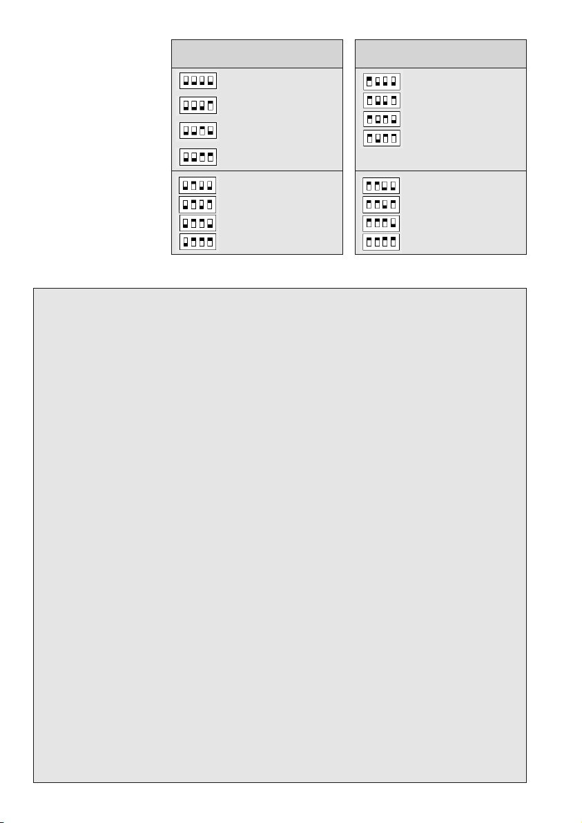
Schalter- T n- T nf lge/T n-
stellung signal f lgefrequenz
Dreiton 5 Hz
Dreiton 10 Hz
Dreiton 15 Hz
Dreiton 20 Hz
Zweiton 5 Hz
Zweiton 10 Hz
Zweiton 15 Hz
Zweiton 20 Hz
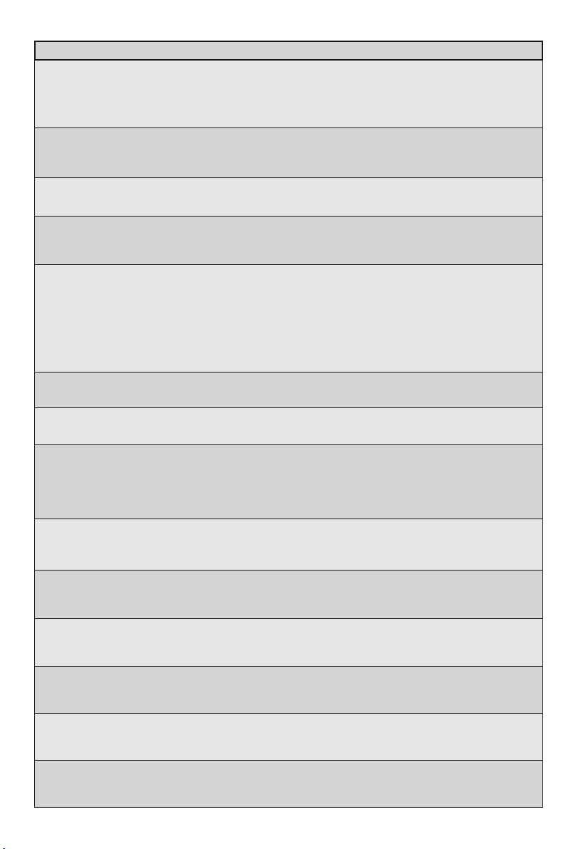
Technische Daten
Typ: 5842/2
Gerätebezeichnung: Ex-Zweitwecker
Gehäuse: Aluminium Druckguss Farbe: schwarz
Gewicht: ca. 0,9 kg
Akustik-Haube: UV-beständiges Makrolon (Polycarbonat) Farbe: schwarz
Abmessungen: ca. 140 x 150 x 120 mm
Kabeleinführung: 1x M20 x 1,5; 1x M12 x 1,5
Anschlussklemmen: 0,75-1,5 mm2/ AWG 14 Klemmvermögen; eindrähtig und feindrähtig
Betriebsgebrauchslage: beliebig (Wandmontage, Deckenmontage*)
Gehäuseschutzart: IP 66
Zündschutzart: II 2G Ex eibmb IIC T6
Konformitätsbescheinigung: DMT 99 ATEX E 095
CE-Kennzeichen: ja, gemäß EMV-Gesetz 11/92
Betriebsumgebungstemperatur: -20ºC bis +40ºC
Lagertemperatur: -40ºC bis +75ºC
Transporttemperatur: -40ºC bis +75ºC
Rel. Luftfeuchte: bis max. 90%
Telefonanschluss: Klemmenbezeichnung D: Lb und W
Rufwechselspannung: 32 VAC bis 75 VAC; 23 Hz bis 54 Hz
überlagerte Speisespannung: 0 VDC bis 63 VDC
Eingangsimpedanz: bei 25 Hz: Z 8 kΩ
bei 50 Hz: Z 4 kΩ
Stromstärke: IK울3 A
Potentialausgleich: Anschluss innen am Gehäuse
Schutzklasse: I
Akustischer Signalgeber: Lautsprecher
Akustisches Signal: 3-Tonruf, Tonfolge: 800 Hz, 1067 Hz, 1333 Hz
2-Tonruf ca. 931 Hz, ca. 1253 Hz
Tonfolgefrequenz: 4 unterschiedliche Einstellungen über Schiebeschalter wählbar
Lautstärke: ca. 90 dB(A) bei 2-Tonruf in 1m Abstand bei 45 V 23 Hz
Wartung: nicht erforderlich
* In Räumen mit starker Staub- oder Wassereinwirkung sollte die Deckenmontage so erfolgen, dass die of-
fene Akustikhaube nach unten gerichtet ist
Einstellen
des T nsignals
Zur Einstellung des Ton-
signals kann entsprechend
der nachstehenden Tabelle
jede beliebige Schalter-
stellung eingestellt werden.
Schalter- T n- T nf lge/T n-
stellung signal f lgefrequenz
Einzelton 180 ms an
70 ms aus
Einzelton 120 ms an
50 ms aus
Einzelton 60 ms an
25 ms aus
Einzelton Dauerton
Wobbelton 1,8 Hz
Wobbelton 3,6 Hz
Wobbelton 3,9 Hz
Wobbelton 7,8 Hz
3
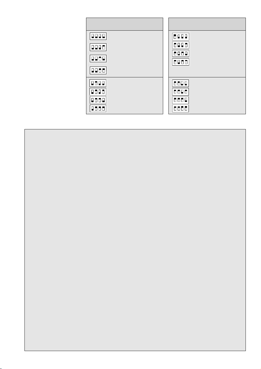
Technical specificati n
Setting the t ne signal
acc rding t the f ll wing
table
any position
of the DIP-
switch may be used to set
the tone signal.
Switch- Signals T ne sequence
psiti n
T
ne seq. frequency
Three-tone 5 Hz
Three-tone 10 Hz
Three-tone 15 Hz
Three-tone 20 Hz
Two-tone 5 Hz
Two-tone 10 Hz
Two-tone 15 Hz
Two-tone 20 Hz
Switch- Signals T ne sequence
psiti n
T
ne seq. frequency
Single tone 180 ms on
70 ms off
Single tone 120 ms on
50 ms off
Single tone 60 ms on
25 ms off
Single tone Continuous
tone
Warble tone 1.8 Hz
Warble tone 3.6 Hz
Warble tone 3.9 Hz
Warble tone 7.8 Hz
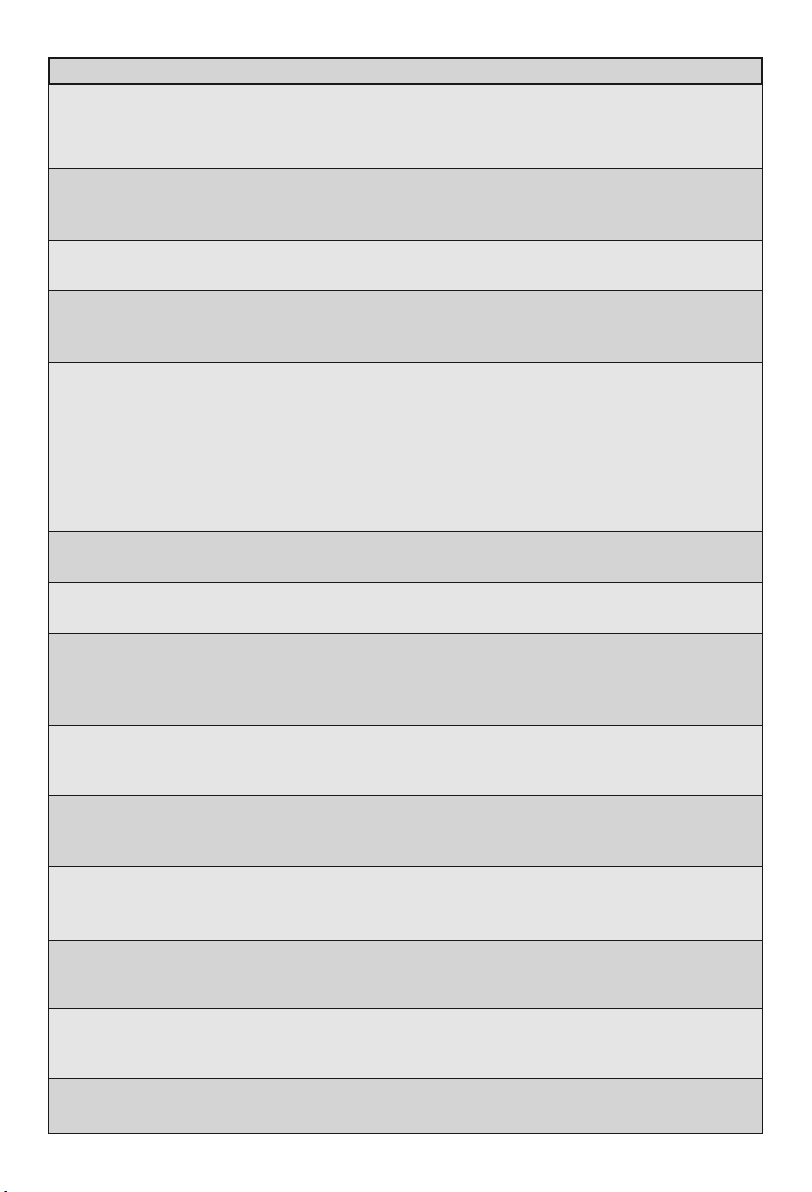
Type: 5842/2
Device designation: Ex-Secondary Sounder
Housing material: Die-casting aluminium Colour: black
Weight: approx. 0.9 kg
Resonant hood material: Makrolon, UV proof (polycarbonate) Colour: black
Physical dimensions: approx. 140 x 150 x 120 mm
Cable entry: 1x M20 x 1.5; 1x M12 x 1.5
Terminals: cable cross section 0.75-1.5 mm2/ AWG 14; single core and fine strand
Operation position: any (wall mount, ceiling mount*)
Protection category: IP 66
Explosion category: II 2G Ex eibmb IIC T6
Certificate of conformity: DMT 99 ATEX E 095
CE label: yes, according to EMC Law 11/92
Ambient operation temperature: -20°C to + 40°C
Storage temperature: -40°C to +75°C
Transport temperature: -40°C to +75°C
Relative humidity: up to max. 90%
Telephone connection: Terminals
D: Lb and W
Ringing alternating current: 32 VAC - 75 VAC; 23 Hz - 54 Hz
Overlaid supply voltage: 0 VDC - 63 VDC
Input impedance: at 25 Hz: Z 8 kΩ
at 50 Hz: Z 4 kΩ
Current intensity: IK울3 A
Equipotential bonding: Connection inside the housing
Insulation class: I
Acoustic signalling device: Loudspeaker
Acoustic signal: 3-tone call, tone sequence: 800 Hz, 1067 Hz, 1333 Hz
2-tone call, approx. 931 Hz, approx. 1253 Hz
Tone sequence frequency: Choice of 4 different DIP switch settings
Sound pressure level: > 90 dB(A) using 2-tone call, at 1 m distance at 45 V 23 Hz
Maintenance: not necessary
* In rooms considerably influenced by dust or water ceiling mounting to be effected the open acoustic hood
showing downwards.
4
Warn- und Sicherheitshinweise
Bei diesem Betriebsmittel handelt es sich um ein explosionsgeschützt ausgeführtes Gerät für den
Betrieb innerhalb explosionsfähiger Gasatmosphäre der Gerätegruppe II, Kategorie 2G in den Zonen
1 und 2.
1. Das Gerät ist in Schutzklasse I aufgebaut und darf nur an der vorgeschriebenen Spannung ange-
schlossen und betrieben werden. Es ist auf einen ordnungsgemäßen Anschluss zu achten.
2. Wartezeit vor dem Öffnen 15 sec.
3. Es ist darauf zu achten, dass das Gehäuse nicht beschädigt wird. Während einer Wartung sind
zugängliche Dichtungen auf Tauglichkeit zu prüfen. Defekte Dichtungen müssen erneuert werden.
4. Das Gerät darf nur unter den an gegebenen Umgebungsbedingungen betrieben werden (siehe
Technische Daten). Widrige Umgebungsbedingungen können zur Beschädigung des Gerätes füh-
ren. Solche widrigen Umgebungsbedingungen sind:
• zu hohe kontinuierliche Luftfeuchtigkeit
• brennbare Gase, Dämpfe, Lösungsmittel, Stäube
• zu niedrige oder zu hohe Umgebungstemperaturen
5. Die vorgeschriebene Betriebsgebrauchslage des Gerätes ist zu berücksichtigen.
6. Das Gerät ist für den Betrieb in Räumen oder im Freien bestimmt.
7. Bei Betrieb des Gerätes sind die gesetzlichen und gewerblichen Vorschriften, Unfallverhütungs-
vorschriften sowie elektrische Be stimmungen und Vorschriften zum Anschluss und Betrieb
an Netzspannung zu beachten. Der An schluss und die Inbetriebnahme darf nur durch einen unter-
wiesenen Fachmann erfolgen.
8. Das Gerät darf nur von unterwiesenem Fach personal geöffnet werden. Beim Öffnen von Ab-
deckungen oder Entfernen von Teilen können spannungs führende Teile freigelegt werden.
9. Vor einer Instandsetzung oder einem Austausch von Teilen muss das Gerät von allen
Spannungsquellen getrennt sein, wenn ein Öffnen des Gerätes erforderlich ist.
10. Bei eventuellen Reparaturen sind nur Originalersatzteile zu verwenden. Abweichende Ersatzteile
können zu Sach- und/oder Personenschäden führen.
11. Wenn eine Reparatur am geöffneten Gerät unter Spannung unvermeidbar ist, darf das nur durch
eine unterwiesene Fachkraft geschehen.
12. Kontinuierliche Beschallung mit dem Gerät und/oder zu geringer Abstand von Personen zur
Schallquelle können Gehörschäden verursachen.
13. Bei den werkseitig bestückten KLE ist die beigefügte Betriebsanleitung zu beachten.
5
Warning and safety n tes
The equipment described in this operating instructions manual is a explosion proof device for use in
hazardous areas. As a device of equipment group II category 2G it is designed for use in gas areas zone
1 and 2.
1. The device is designed in compliance with insulation class I and may be connected and operated
at the mandatory voltage only. A proper connection must be especially observed.
2. Waiting time until opening 15 sec.
3. Take care not to damage the housing. During maintenance, check accessible seals for function.
Damaged seals must be replaced.
4. The device may be operated under the mandatory ambient conditions only (refer to Technical
specifications). Bad ambient conditions may lead to damage to the device. Such bad ambient
conditions are:
• too high continuous air humidity
• inflammable gases, vapours, solvents, dusts
• too low or too high ambient temperatures
5. The mandatory operational position of the device must be considered.
6. The device is meant for use indoors or outdoors.
7. During operation of the device the legal and professional regulations, the safety regulations, and
the electrical rules and regulations regarding connection and operation with line voltage must be
observed. Connection and commissioning may be done by an educated professional only.
8. The device may be opened by educated professional personnel only. During the process of ope-
ning covers or removing parts live parts may be exposed.
9. If repairs or a replacement of parts include opening the device, the device must be separated
from all power sources prior to such work.
10. In case of repairs only original spare parts may be used. Any other spare parts may lead to
personal injury and/or equipment damage.
11. If it is unavoidable to repair the powered device, this may be done by an educated professional
only.
12. Continuous subjection to signalling and/or too small distance to the signalling source may cause
hearing damage.
13. In case of factory fitted cable glands the attached operating instructions have to be considered.

Änderungen und Irrtum vorbehalten
Subject to alterations or errors
FHF Funke + Huster Fernsig GmbH
Gewerbeallee 15-19 · D-45478 Mülheim an der Ruhr · Web:
www.fhf.de
Phone +49 - 208-8268-0 · Fax +49- 208-8268-286 ·
Mail: info fhf.de
Orders: fhf-orders eaton.com · Requests: fhf-sales eaton.com
Support: fhf-support eaton.com
Table of contents
Other FHF Marine Equipment manuals


