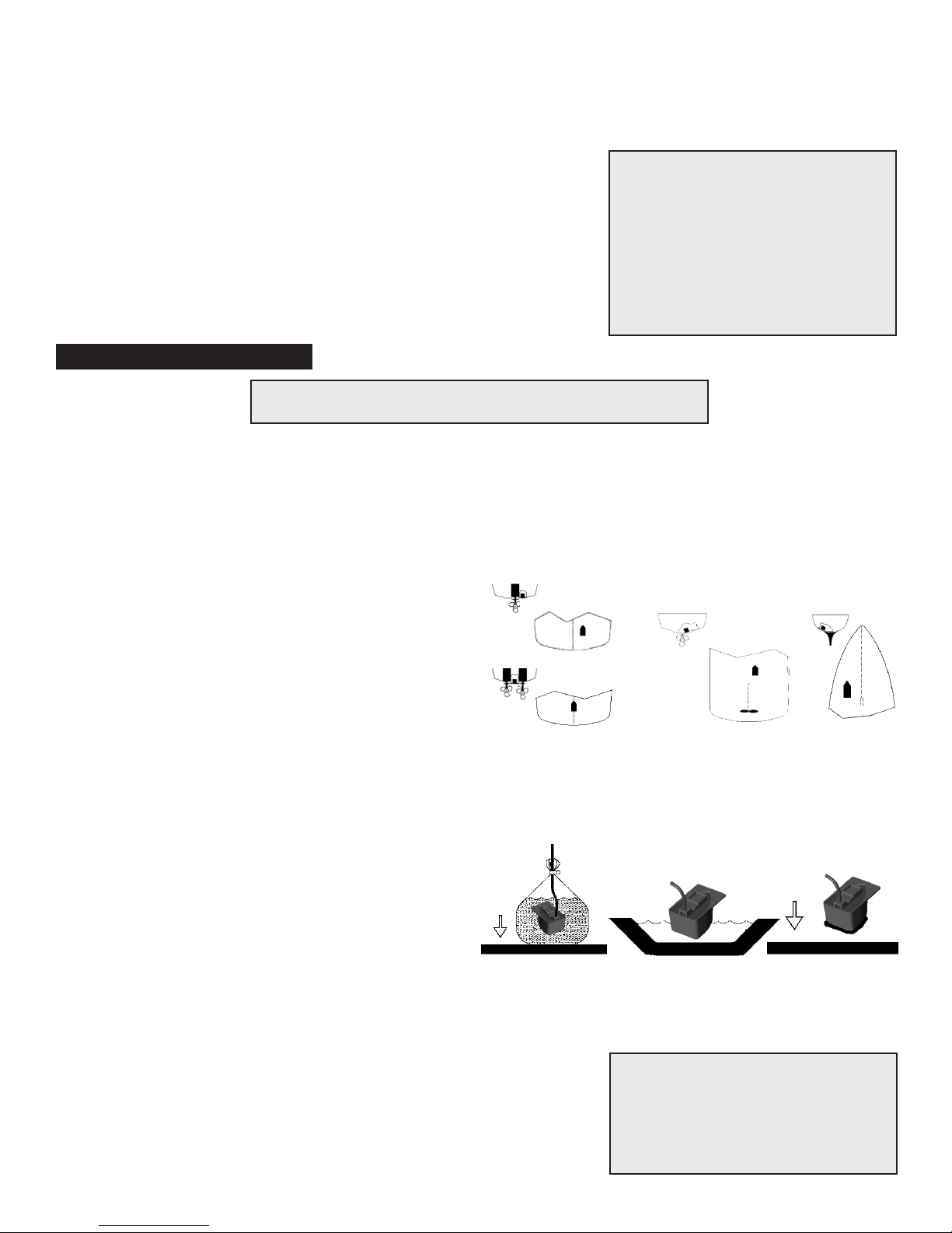
Gluing In Place
1. All surfaces to be bonded must be smooth, clean and dry. If the hull surface is not smooth, sand it with 30
grit sandpaper until a smooth surface is obtained in an area a little larger in diameter than the length of the
transducer.
2. Clean and dry both the selected area and the face of the transducer with a weak solvent to remove any dust,
grease or oil.
3. Prepare the adhesive as per the directions supplied with the adhesive.
4. Apply a generous amount of adhesive to the center of the face of the transducer (side opposite from the cable).
5. Press the transducer face onto the hull with a twisting motion to expel all air bubbles. (If the hull is slanted, temporarily secure the transducer in place
with duct tape.) Allow the adhesive to cure as per the manufacturer’s instructions.
6. After the adhesive has cured, route the cable to the depth sounder mounting location. To reduce electrical interference, separate the transducer cable
from other electrical wiring and coil and secure the excess cable in place using tie-wraps.
The Depth Reading on the Depth Sounder is Random, Flashing, and Inconsistent
1. Operate the unit under normal operating specifications and check to see if it operating properly (pay attention to minimum and maximum depth capabil-
ities).
2. If this condition occurs only at certain speeds, then a transducer adjustment is needed. Refer to the “Helpful Hints for Transducer Installation” section
below. Refer to the Transducer Adjustment Instructions for adjustment procedures.
3. Under certain circumstances sonar may not perform at the best of its ability. Extremely dirty water, very soft bottom, high speeds, deep water, or a
combination of the above will result in incomplete or inaccurate readings. Please refer to the Transducer Adjustment Instructions to minimize the effects
of these conditions.
4. If the transducer is transom mounted check to make sure that the transducer is not “kicked-up”. To prevent damage to the transducer, it will automati-
cally release from mounting bracket (kick-up) when it is impacted. If this occurs refer to the Transducer Installation Instructions to reset the transducer
for normal operation. If this happens frequently make sure that the trailer or boat lift bunks do not interfere with the transducer during loading and unload-
ing.
5. Check the transducer cable connection on the back of the depth sounder. Make sure that the connection is made as per the instructions supplied with
the depth sounder.
6. Contact NMP at 888-667-2767 for assistance if you are unable to correct the problems.
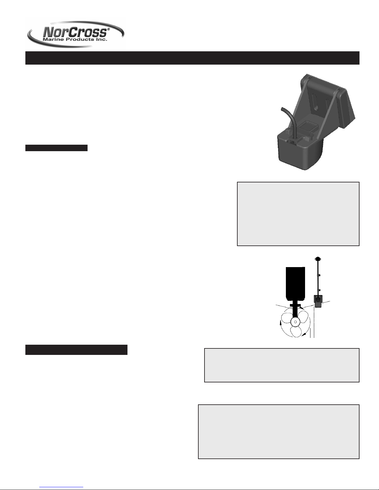
Helpful Hints for Transducer Installation (Transom Mounting)
1. Make sure the transducer is not mounted in any area where the water flow is interrupted by propeller turbulence or aer-
ated water. If standing at eye level, behind the transducer and looking forward along the bottom of the boat hull there
should NOT be any strakes, chimes, steps, or hull fittings inline with the transducer. If there are any of these obstruc-
tions, the transducer will need to be relocated to achieve optimal performance. The transducer CAN NOT be transom
mounted on a Stepped-Hull vessel, it must only be in-hull mounted.
2. Make sure that the leading edge (bow - side closest to the bow of the boat) of the transducer extends at least 1/8” (3
mm) below the bottom of the hull. Also make sure that the trailing edge (stern - side furthest from the bow of the boat)
is 1/16” to 1/18” (1-3 mm) below the leading edge.
Helpful Hints for Transducer Installation (In-Hull Mounting)
1. The hull must be made out of solid fiberglass or a maximum 1/8” (3 mm) aluminum. The unit will not work through wood, plastic, or any other compos-
ite material.
2. The glue in location must be in direct contact with the water at all times during operation. The transducer CAN NOT be mounted in any area where the
water flow is interrupted by propeller turbulence or aerated water. It MUST NOT be mounted behind any strakes, chimes, steps, or hull fittings that will
disrupt the flow of clean water to the transducer (in line with the mounting location of the transducer and the bow of the boat). If there are any of these
obstructions, the transducer will need to be relocated to achieve optimal performance.
3. If mounting in-hull on a stepped hull vessel, the transducer must be mounted in a location where there are no steps forward of the transducer (between
the transducer mounting location and the bow of the boat). Keep in mind that the glue in location must be in direct contact with the water at all times
during operation or incorrect depth readings will occur.
The Transducer Cable Supplied with the Transducer is Too Short for My Installation, Can It Be Extended
YES: To extend the transducer cable:
1. Cut the cable on the transducer side 1” (28 mm) from the plug. If the depth sounder display also has a plug, you will need to cut this plug off as well.
2. At both cuts, strip back the rubber cable cover 1” (28 mm) exposing the three internal wires (blue, white, and bare).
3. Using a soldering iron, solder the desired length extension cable (available at a boating supply store or by calling 888-667-2767) between the depth
sounder display and the transducer. Be certain that the blue, white and bare wires are connected properly between the depth sounder display and the
transducer and make sure the colors are consistantly matched throughout the splice.
4. Using electrical tape, or heat shrink tubing make certain that the soldered connections are complete-
ly sealed and protected
against accidental electrical interference.
TROUBLESHOOTING GUIDE
Sonar Beam Angle 20 Degrees
Sonar Frequency 200 KHZ
Transducer Cable Length 25 Feet (7.6 M)
6450 Kingspoint Parkway, Suite 6
Orlando, FL 32819
www.norcrossmarine.com
(p) 888-667-2767
Specifications
WARNING: Disassembly of the electronic components
within this unit may result in exposure to lead in the form
of solder, which is known to the state of California to cause
cancer, birth defects, and other reproductive harm.
©2004 Norcross Marine Products, Inc., All rights reserved. All specifications are subject to change without notice.
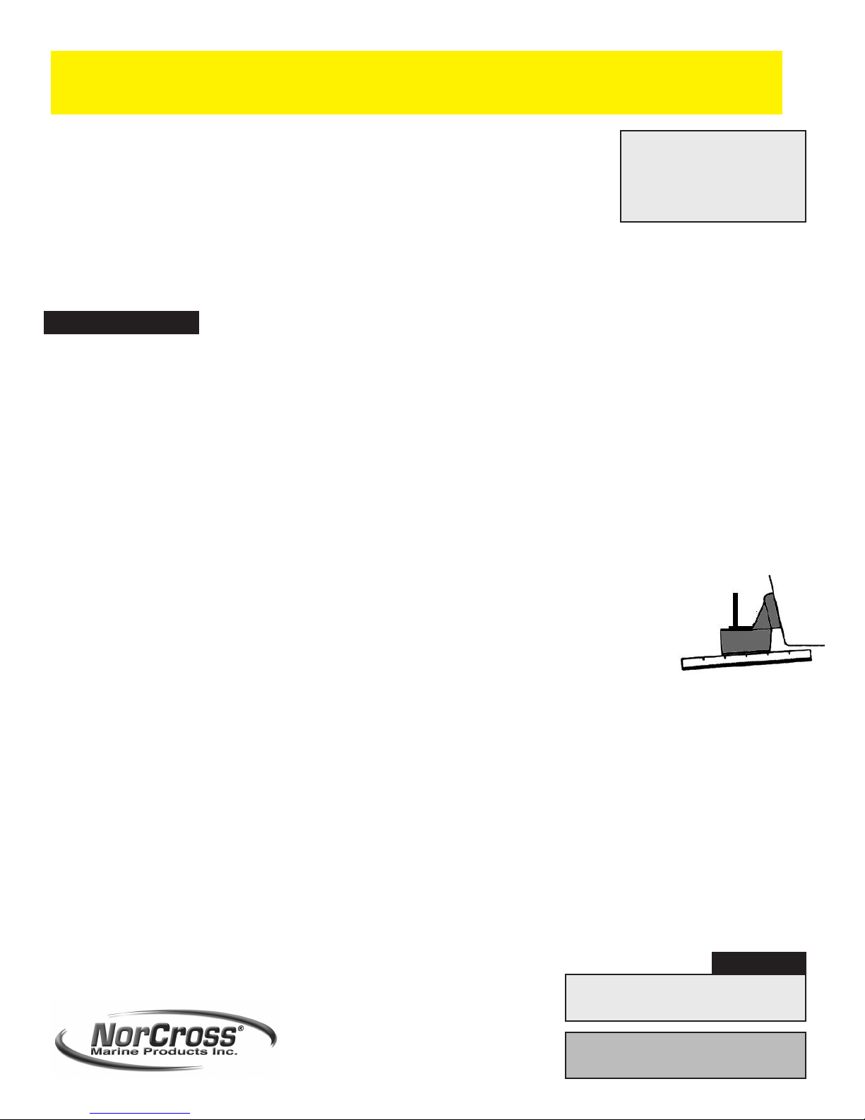
WARNING!!!!
DO NOT glue the transducer in
place until the location is tested
as per the “Testing at the
Selected Location” section in
this manual.
Figure 9
slight angle
-4-
Selecting the Adhesive
Use a viscous slow-cure epoxy or a fairly rigid, one part adhesive sealant. In cold climates, a one-part polyurethane adhesive, such as Boat-Life’s
Life Seal‚ may be best. Do not use “5 minute” epoxies because they are generally brittle. RTV (silicone) adhesives (Weather Sealants, “Rubbery”
Caulks, 3M 5200, etc) are not recommended because most of the sound energy is lost.