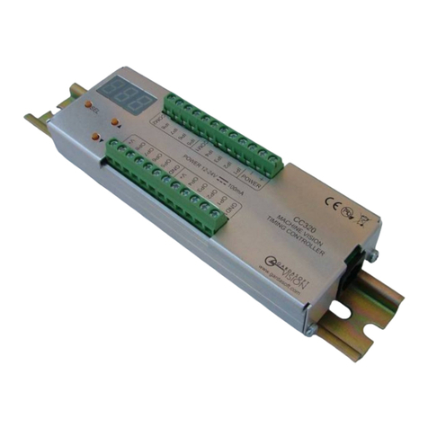
GARDASOFT CC320 User manual

www.gardasoft.com
CC320 Trigger Timing Controller
User Manual
Version 015

|2
Copyright and disclaimer notice
Except as prohibited by law:
All hardware, software and documentation is provided on an ‘as is’ basis. This information
is for guidance only. Installers must perform their own risk assessment specic to each
installation.
It is essential that the user ensures that the operation of the product is suitable for their
application.
The user must ensure that incorrect functioning of this equipment cannot cause any dan-
gerous situation or signicant nancial loss to occur.
Deliberate acts of endangerment and vandalism are not covered by this document and
must be considered by the installer.
While care has been taken in the preparation of this document Gardasoft Vision Ltd will
not accept any liability for consequential loss of any kind except those required by law.
All trademarks acknowledged. This document is copyright 2023 Gardasoft Vision Ltd.
EC conformity declaration
The EC Certicate of Conformity is available from Gardasoft Vision Ltd on request
Issue status of this document: Issue 015 (April 2023)

3|
www.gardasoft.com
Contents
1 Getting started 7
2 Safety 7
2.1 Electrical 8
2.2 General 8
3 Sicherheit 8
3.1 Elektrik 8
3.2 Allgemeines 9
4 Sécurité 9
4.1 Électricité 9
4.2 Général 10
5 Mounting 10
6 Connections 11
6.1 Power supply 12
6.2 Digital inputs 12
6.3 Digital outputs 13
6.4 Ethernet connector 15
6.5 Connecting a CC320 to other devices 15
6.5.1 Connecting the output to a 24V input 15
6.5.2 Connecting the input to a 24V output 16
6.5.3 Connecting the output to an opto-coupled input 16
6.5.4 Connecting the input to an opto-coupled output 17
6.5.5 Connecting the output to an open-collector input 17
6.5.6 Connecting the input to an open-collector output 18

|4
6.5.7 Connecting the output to a TTL input 18
6.5.8 Connecting the input to a TTL output 19
6.5.9 Connecting the input to an LVDS output 19
6.5.10 Connecting the output to an LVDS input 20
6.5.11 Connecting the output to an RS422 input 21
6.5.12 Connecting the input to an RS422 output 22
7 Operation 22
7.1 Input modes 23
7.1.1 Encoder operation 23
7.1.2 Free running trigger 24
7.2 Output Modes 24
7.3 Flags 45
7.3.1 Ethernetmessageag(E) 46
7.3.2 FIFOag(F) 47
7.3.3 Resyncag(R) 47
7.3.4 Pulseag(P) 47
7.4 Logic Operations 48
7.4.1 NOT 48
7.4.2 AND 48
7.4.3 NAND 49
7.4.4 OR 49
7.4.5 NOR 50
7.5 Virtual channels 50
7.6 Cold boot 51

5|
www.gardasoft.com
8 Ethernet setup 52
8.1 Connection 52
8.2 IP Address 52
8.2.1 DHCP 53
8.2.2 Fixed IP address 54
8.3 Controller Search 54
8.4 Enquiry Packets 54
9 Webpageconguration 55
9.1 Main page 56
9.2 Channel conguration page 56
9.3 General setup page 57
10 Commandconguration 57
10.1 Communication 58
10.2 Command structure 58
10.3 Commands 59
10.4 Command summary 67
Appendix A - Timing 68
Appendix B - Error codes 69
Appendix C - Examples 70
Integrating smart cameras 70
Sequenced pulses 71
Gated pulses 72
Delayed signal 73
Belt position triggering 74

|6
Pulse burst 75
Simple FIFO mode 76
Resync mode 77
Resync and FIFO mode 79
AppendixD-Congurationsheet 80

7|
www.gardasoft.com
1 Getting started
Read Section 2 , “Safety” (or Abschnitt 3 , “Sicherheit”, or Section 4 ,
“Sécurité”) and Section 7, “Operation” and check the CC320 fulls your
requirements.
Mount the CC320 as described in Section 5, “Mounting” using either the
DIN rail or the mounting holes.
Connect the CC320 as described in Section 6, “Connections”. When the
CC320 powers up it should show two alternating lines on the display
to indicate that it is operating properly. Three indicator LEDs on the
outputs should be pulsing in sequence every second.
Connect Ethernet to the CC320 and set it up according to Section 8,
“Ethernet setup”.
Use a web browser or the GardasoftMaint program (available from
www.gardasoft.com) to congure the unit.
To congure the CC320 without an Ethernet connection, you can
use the keypad on the front panel. Visit www.gardasoft.com to view
Application Note APP987 explaining the use of the keypad.
Visit www.gardasoft.com for further Application Notes giving additional
information on the use of the CC320.
2 Safety
Read this before using the CC320. Always observe the following safety
precautions. If in doubt, contact your distributor or Gardasoft Vision.
The following symbols mean:
Warning: Read instructions to understand possible
hazards.
Warning: Possible hazardous voltage.
Where these symbols appear in the manual, refer to the text for
precautions to be taken.

|8
2.1 Electrical
The user must ensure that the potential dierence between any
combination of applied signals does not exceed the supply voltage.
The CC320 does not have complete tracking isolation of inputs and
outputs.
Transients caused by inductive loads must be suppressed externally to
the CC320.
2.2 General
The CC320 must not be used in an application where its failure could
cause a danger to personal health or damage to other equipment.
If the equipment is used in a manner not specied by the manufacturer,
the protection provided by the equipment may be impaired.
3 Sicherheit
Bitte lesen Sie dieses Dokument, bevor Sie die CC320 verwenden.
Beachten Sie immer die folgenden Sicherheitshinweise. Bei Fragen
wenden Sie sich an Ihren Händler oder an Gardasoft Vision. Die
folgenden Symbole bedeuten:
Warnung: Lesen Sie die Anleitung, um die mögliche
Gefährenquelle zu verstehen.
Warnung: Mögliche gefährliche Spannung.
Wenn diese Symbole in der Anleitung erscheinen, nden Sie im
beistehenden Text die zu ergreifenden Vorsichtsmaßnahmen.
3.1 Elektrik
Der Benutzer muss sicherstellen, dass der Potenzialunterschied
zwischen jeder beliebigen Kombination an angelegten Signalen die
Versorgungsspannung nicht überschreitet.

9|
www.gardasoft.com
Die CC320 verfügt über keine vollständige Nachlauf-Isolierung der Ein-
und Ausgänge.
Spannungsspitzen am CC320 aufgrund von induktiven Ladungen
müssen extern unterdrückt werden.
3.2 Allgemeines
Die CC320 darf nicht in Bereichen verwendet werden, in denen bei
Ausfall eine Gefahr von Personen - oder Sachschäden besteht.
Wenn das Gerät nicht entsprechend den Herstellerangaben eingesetzt
wird, kann der durch das Gerät bereitgestellte Schutz beeinträchtigt
werden.
4 Sécurité
Veuillez lire la notice avant d’utiliser le CC320. Respectez toujours les
mesures de sécurité qui suivent. En cas de doute, contactez votre
distributeur ou Gardasoft Vision. Les symboles suivants signient:
Attention: Lisez les consignes an de bien comprendre
les dangers encourus.
Attention: Risque d’électrocution.
Veuillez vous référer aux consignes du manuel pour connaître les
précautions à suivre au regard de ces symboles.
4.1 Électricité
L’utilisateur doit s’assurer que la diérence de potentiel entre toute
combinaison des signaux appliqués ne dépasse pas la tension de
fourniture.
Le CC320 ne dispose pas de système complet d’isolation des entrées et
sorties.
Les transitoires causés par les charges inductives doivent être
supprimés à l’extérieur du CC320.

|10
4.2 Général
Le CC320 ne doit pas être utilisé dans une situation où toute panne
de celui-ci mettrait en danger la santé des personnes ou risquerait
d’endommager d’autres équipements.
Si l’appareil est utilisé d’une manière diérente de celle recommandée
par le fabricant, la protection oerte par l’appareil pourra en être
altérée.
5 Mounting
The CC320 can be mounted onto a panel using the M3 threaded holes
in the base, shown in the diagram below.
Note: Ensure the mounting screws protrude no further than 6mm from
the surface to which the CC320 is to be attached.
The PP703 kit is available for mounting the CC320 on a DIN rail. The
dimensions in the diagrams below are all in millimetres.

11 |
www.gardasoft.com
The CC320 does not have an IP rating and should be mounted such that
moisture and dirt cannot enter the unit.
The CC320 is a re enclosure as long as the following conditions are
met:
»The Ethernet connector must not be facing downwards and,
»The mounting holes on the base must be covered or have a screw tted
6 Connections
All connections except Ethernet are available on screw terminals. The
CC320 top panel connections are shown below:

|12
6.1 Power supply
The power supply must be 12VDC to 24VDC regulated. The maximum
current required is 100mA. The maximum heat dissipation is 2.4W.
Caution: Do not connect a power supply to the V+out connections. This
is a low power reference voltage.
6.2 Digital inputs
The state of each input is shown on an LED next to the connector. The
inputs are arranged in two groups of 4, each group having a common
negative connection. This is summarised below:
Connector Function
POWER + Power supply, 12V to 24V
POWER − Power supply 0V
IP1 Input 1 positive
IP2 Input 2 positive
IP3 Input 3 positive
IP4 Input 4 positive
COM1 Common negative for inputs 1, 2, 3, 4
IP5 Input 5 positive
IP6 Input 6 positive
IP7 Input 7 positive
IP8 Input 8 positive
COM2 Common negative for inputs 5, 6, 7, 8

13 |
www.gardasoft.com
The CC320 inputs are optically coupled and the equivalent circuit is
shown below:
An input voltage between 5V and 24V is recognised by the CC320 as a
logic level ‘1’. An input voltage of 2V or less is recognised as a logic level
‘0’.
Referring to the diagram above, the forward voltage VFis typically 1.5V.
The input current IIN is 1.8mA at 5V and 11.3mA at 24V.
6.3 Digital outputs
The state of each output is shown on an LED next to the connector. The
connection details are shown in the table below:
Connector Function
GND1 Common 0V for outputs 1, 2, 3, 4
OP1 Output 1 open drain
OP2 Output 2 open drain
OP3 Output 3 open drain
OP4 Output 4 open drain
V+out
Low power regulated output. Maximum
source current 50mA.
Caution! Do not connect a PSU to V+out

|14
Connector Function
GND2 Common 0V for outputs 5, 6, 7, 8
OP5 Output 5 open drain
OP6 Output 6 open drain
OP7 Output 7 open drain
OP8 Output 8 open drain
V+out
Low power regulated output. Maximum
source current 50mA.
Caution! Do not connect a PSU to V+out
The CC320 equivalent circuit for the output is shown below:
The voltage between the output and ground must not be greater than
24V and the output can only sink up to 50mA.
If the output is shorted to a voltage higher than 5V then the output may
be damaged.
Do not draw more than 50mA from the V+out connections as this can
aect the internal operation of the controller. These outputs are just to
be used for low current, for example pull-up resistors.

15 |
www.gardasoft.com
6.4 Ethernet connector
The RJ45 Ethernet connector requires a straight through cable to
connect into a network switch, hub or router. It runs at 10Mbits per
second.
6.5 Connecting a CC320 to other devices
Use the following examples to help you connect your CC320 to other
devices in your system:
6.5.1 Connecting the output to a 24V input

|16
6.5.2 Connecting the input to a 24V output
6.5.3 Connecting the output to an opto-coupled input

17 |
www.gardasoft.com
6.5.4 Connecting the input to an opto-coupled output
6.5.5 Connecting the output to an open-collector input

|18
6.5.6 Connecting the input to an open-collector output
6.5.7 Connecting the output to a TTL input

19 |
www.gardasoft.com
6.5.8 Connecting the input to a TTL output
6.5.9 Connecting the input to an LVDS output

|20
6.5.10 Connecting the output to an LVDS input
Other manuals for CC320
1
Table of contents
Other GARDASOFT Controllers manuals

GARDASOFT
GARDASOFT TR-CL Series User manual

GARDASOFT
GARDASOFT OC-G-5646-2-ET User manual

GARDASOFT
GARDASOFT PP600 User manual

GARDASOFT
GARDASOFT CC320 User manual

GARDASOFT
GARDASOFT RC1 Series User manual

GARDASOFT
GARDASOFT PP420 User manual
GARDASOFT
GARDASOFT CL190 User manual

GARDASOFT
GARDASOFT TR-HT2 Series User manual
GARDASOFT
GARDASOFT RC100 User manual

GARDASOFT
GARDASOFT PP600F LED User manual