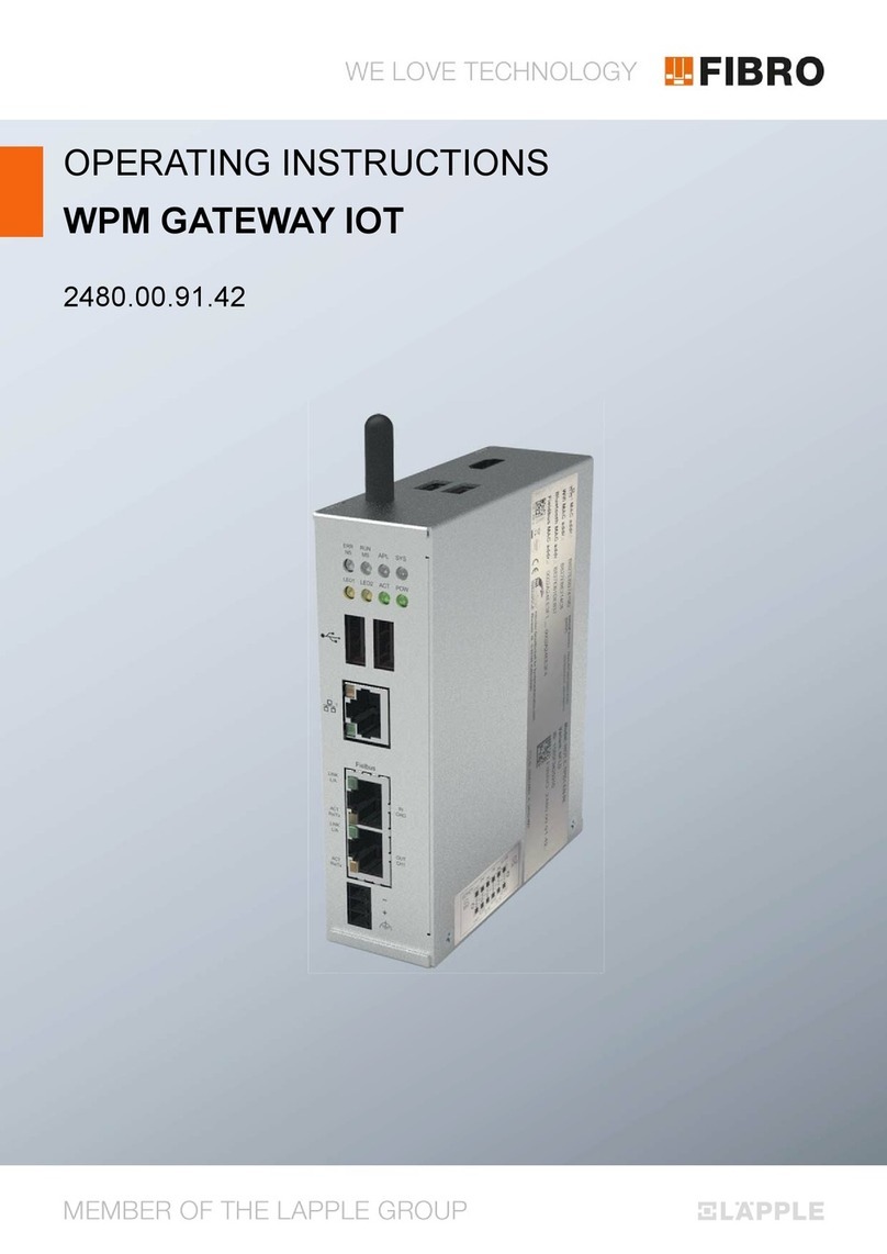
FIBRO 2480.00.91.40 User manual

WE LOVE TECHNOLOGY
MEMBER OF THE LAEPPLE GROUP
OPERATING INSTRUCTIONS
ETHERCAT WPM GATEWAY FIELDBUS
2480.00.91.40
Operating instructions EtherCatWPM Gateway Fieldbus

Document: Operating instructions
Document number: 2.7544.00.0718.0100000
Revision: R07-2018
Version: V00
Language:
In the German language, this document is the original version in the EU language of the manufacturer and is labelled
with the German national flag.
In the EU language of a country of use, this document is a translation of the original version and labelled with the
national flag of the country of use.
This document is referred to as "instructions" in the following text.
Number of pages in this manual including the title page: 40
These instructions are valid for the product
2480.00.91.40
EtherCat WPM Gateway Fieldbus
This document was created by
FIBRO GMBH
August-Läpple-Weg
DE 74855 Hassmersheim
Phone: +49 (0) 62 66 73 0
Fax: +49 (0) 62 66 73 237
E-mail: [email protected]
Internet: www.fibro.de
© All rights to this document are subject to copyright of the author.
Without the prior written permission of FIBRO GMBH, this document must not be copied or
reproduced, either in full or in part.
The instructions are intended only for the operator of the described Interface only
and must therefore not be made available to uninvolved third parties - in particular to competitors.

Operating instructions EtherCatWPM Gateway Fieldbus 3/40
Contents
1 Introduction . . . . . . . . . . . . . . . . . . . . . . . . . . . . . . . . . . . . . . . . . . . . . . . . . . . . . . . . . . . . . . . 5
1.1 Intended use . . . . . . . . . . . . . . . . . . . . . . . . . . . . . . . . . . . . . . . . . . . . . . . . . . . . . . . . . . 5
1.2 Foreseeable misuse. . . . . . . . . . . . . . . . . . . . . . . . . . . . . . . . . . . . . . . . . . . . . . . . . . . . . 6
1.3 Scope of application. . . . . . . . . . . . . . . . . . . . . . . . . . . . . . . . . . . . . . . . . . . . . . . . . . . . . 6
1.4 Disclaimer of liability . . . . . . . . . . . . . . . . . . . . . . . . . . . . . . . . . . . . . . . . . . . . . . . . . . . . 6
1.5 Purpose of the document. . . . . . . . . . . . . . . . . . . . . . . . . . . . . . . . . . . . . . . . . . . . . . . . . 7
1.6 Target group. . . . . . . . . . . . . . . . . . . . . . . . . . . . . . . . . . . . . . . . . . . . . . . . . . . . . . . . . . . 7
1.7 Copyright . . . . . . . . . . . . . . . . . . . . . . . . . . . . . . . . . . . . . . . . . . . . . . . . . . . . . . . . . . . . . 7
2 Safety . . . . . . . . . . . . . . . . . . . . . . . . . . . . . . . . . . . . . . . . . . . . . . . . . . . . . . . . . . . . . . . . . . . . 8
2.1 Safety instructions . . . . . . . . . . . . . . . . . . . . . . . . . . . . . . . . . . . . . . . . . . . . . . . . . . . . . . 8
2.2 General instructions . . . . . . . . . . . . . . . . . . . . . . . . . . . . . . . . . . . . . . . . . . . . . . . . . . . . . 8
3 Product description . . . . . . . . . . . . . . . . . . . . . . . . . . . . . . . . . . . . . . . . . . . . . . . . . . . . . . . . . 9
3.1 Components and properties. . . . . . . . . . . . . . . . . . . . . . . . . . . . . . . . . . . . . . . . . . . . . . . 9
3.2 Accessories . . . . . . . . . . . . . . . . . . . . . . . . . . . . . . . . . . . . . . . . . . . . . . . . . . . . . . . . . . . 9
4 Assembly . . . . . . . . . . . . . . . . . . . . . . . . . . . . . . . . . . . . . . . . . . . . . . . . . . . . . . . . . . . . . . . . 10
4.1 Constructive requirements . . . . . . . . . . . . . . . . . . . . . . . . . . . . . . . . . . . . . . . . . . . . . . . 10
5 Commissioning . . . . . . . . . . . . . . . . . . . . . . . . . . . . . . . . . . . . . . . . . . . . . . . . . . . . . . . . . . . 11
5.1 Preliminary conditions . . . . . . . . . . . . . . . . . . . . . . . . . . . . . . . . . . . . . . . . . . . . . . . . . . 11
5.2 Electrical connection . . . . . . . . . . . . . . . . . . . . . . . . . . . . . . . . . . . . . . . . . . . . . . . . . . . 11
5.2.1 Digital inlets . . . . . . . . . . . . . . . . . . . . . . . . . . . . . . . . . . . . . . . . . . . . . . . . . . . . 12
5.2.2 Digital outlets . . . . . . . . . . . . . . . . . . . . . . . . . . . . . . . . . . . . . . . . . . . . . . . . . . . 13
5.2.3 Relays . . . . . . . . . . . . . . . . . . . . . . . . . . . . . . . . . . . . . . . . . . . . . . . . . . . . . . . . 14
5.2.4 EtherCAT Fieldbus. . . . . . . . . . . . . . . . . . . . . . . . . . . . . . . . . . . . . . . . . . . . . . . 15
5.2.5 Voltage supply . . . . . . . . . . . . . . . . . . . . . . . . . . . . . . . . . . . . . . . . . . . . . . . . . . 16
5.2.6 Deactivated - USB device BT LE 4.0 Interface . . . . . . . . . . . . . . . . . . . . . . . . . 16
5.2.7 Ethernet interface . . . . . . . . . . . . . . . . . . . . . . . . . . . . . . . . . . . . . . . . . . . . . . . 16
6 Operation . . . . . . . . . . . . . . . . . . . . . . . . . . . . . . . . . . . . . . . . . . . . . . . . . . . . . . . . . . . . . . . . 17
6.1 LED displays on the device . . . . . . . . . . . . . . . . . . . . . . . . . . . . . . . . . . . . . . . . . . . . . . 17
6.2 Configuration operation . . . . . . . . . . . . . . . . . . . . . . . . . . . . . . . . . . . . . . . . . . . . . . . . . 18
6.3 Normal operating modes . . . . . . . . . . . . . . . . . . . . . . . . . . . . . . . . . . . . . . . . . . . . . . . . 18
6.3.1 Normal digital I/O operation . . . . . . . . . . . . . . . . . . . . . . . . . . . . . . . . . . . . . . . . 18
6.3.2 Pairing of the WPM data holder and WPM Gateway. . . . . . . . . . . . . . . . . . . . . 20
6.3.3 Operation with EtherCAT Fieldbus. . . . . . . . . . . . . . . . . . . . . . . . . . . . . . . . . . . 22
6.3.4 (deactivated) USB communication with BT LE module . . . . . . . . . . . . . . . . . . . 30
7 Maintenance . . . . . . . . . . . . . . . . . . . . . . . . . . . . . . . . . . . . . . . . . . . . . . . . . . . . . . . . . . . . . . 31
7.1 Changing the battery . . . . . . . . . . . . . . . . . . . . . . . . . . . . . . . . . . . . . . . . . . . . . . . . . . . 31
7.1.1 Lithium metal battery real-time clock . . . . . . . . . . . . . . . . . . . . . . . . . . . . . . . . . 31
8 Disposal . . . . . . . . . . . . . . . . . . . . . . . . . . . . . . . . . . . . . . . . . . . . . . . . . . . . . . . . . . . . . . . . . 32
8.1 Disposing of the battery . . . . . . . . . . . . . . . . . . . . . . . . . . . . . . . . . . . . . . . . . . . . . . . . . 32

4/40 Operating instructions EtherCatWPM Gateway Fieldbus
9 Technical data . . . . . . . . . . . . . . . . . . . . . . . . . . . . . . . . . . . . . . . . . . . . . . . . . . . . . . . . . . . . 33
9.1 Type plate . . . . . . . . . . . . . . . . . . . . . . . . . . . . . . . . . . . . . . . . . . . . . . . . . . . . . . . . . . . 33
9.2 Technical drawing . . . . . . . . . . . . . . . . . . . . . . . . . . . . . . . . . . . . . . . . . . . . . . . . . . . . . 34
10 Indexes . . . . . . . . . . . . . . . . . . . . . . . . . . . . . . . . . . . . . . . . . . . . . . . . . . . . . . . . . . . . . . . . . . 35
10.1 Third-party products. . . . . . . . . . . . . . . . . . . . . . . . . . . . . . . . . . . . . . . . . . . . . . . . . . . . 35
11 Appendix. . . . . . . . . . . . . . . . . . . . . . . . . . . . . . . . . . . . . . . . . . . . . . . . . . . . . . . . . . . . . . . . . 37
11.1 Personal notes . . . . . . . . . . . . . . . . . . . . . . . . . . . . . . . . . . . . . . . . . . . . . . . . . . . . . . . . 37

Operating instructions EtherCatWPM Gateway Fieldbus 5/40
Introduction
1 INTRODUCTION
Read through these instructions carefully before use and store them.
These instructions contain the following important information on the product:
• Proper use
• Safety
• Mounting
•Use
• Maintenance
• Disposal
Proper use also involves
• Reading these instructions
• Complying with the safety information they contain
• Complying with the applicable documents
• Complying with the maintenance requirements
Give these instructions to the user after mounting is complete, and give them to the new owner
if the product is sold.
1.1 Intended use
• This product is intended only for industrial use in the territory of the European Union and in
countries that have been recognised by standards and certificates of the European Union.
Country-specific restrictions may exist concerning communication via outside of the European
Union.
• The WPM system is intended only for industrial use in machinery and plant technology.
• The product is a telecommunications product.
• The product may be used only in a technically flawless state, for its intended use, in compli-
ance with the relevant provisions and with safety and potential dangers kept in mind.
• Detected disruptions, especially those which could impair safety, must be redressed imme-
diately.
All forms of usage deviating from the one described in the section on proper use and in the rel-
evant documentation is not proper and is thus prohibited.
• The distributing companies and manufacturers assume no liability for damage in the event
of improper use.
• The manufacturer assumes no liability for equipment, its usage and consequences.
• The operator shall be the sole bearer of all risks associated with improper use.

6/40 Operating instructions EtherCatWPM Gateway Fieldbus
Introduction
1.2 Foreseeable misuse
use, propermisusemisuse
The product must not be stressed beyond its load limits.
The following instances, among others, are considered misuse:
• It is used for applications which the manufacturer has not explicitly approved. The state-
ments contained in the safety notes in the relevant documentation must be observed!
• Construction changes that destroy the original state.
• Improper system programming or configuration. The operator bears sole responsibility and
risks for using, programming and configuring the system.
• Usage in explosive atmospheres.
• Usage in explosive areas.
• Usage in medical areas.
• Usage in residential areas.
• Usage in applications that are relevant to security.
• Private use.
1.3 Scope of application
These instructions apply to the product with the description “EtherCatWPM Gateway” manufac-
tured by FIBRO GMBH DE 74855 Hassmersheim.
If you do not have the proper instructions for your product, contact
FIBRO GMBH DE 74855 Hassmersheim.
1.4 Disclaimer of liability
FIBRO GMBH guarantees the described function of the product as stated in advertising and
product information.
Further product properties are not confirmed. FIBRO GMBH assumes no liability for efficiency
and flawless functioning if the product is used for a purpose other than the one addressed in the
chapter “Proper use”. Compensation for damage is generally precluded.
If this product is used in environments for which it is not suitable or which do not fulfil the tech-
nical standards, FIBRO GMBH shall not be held responsible for the consequences.
FIBRO GMBH assumes no liability for damage to facilities and systems near the product caused
by a defect in the product or an error in these instructions.
FIBRO GMBH is not responsible for the violation of patents and/or the rights of third parties out-
side of the Federal Republic of Germany.
FIBRO GMBH is not responsible for damage caused by improper operation and failure to follow
the instructions provided in this document.
FIBRO GMBH is not liable for lost profit and subsequent damage resulting from failure to comply
with safety and warning notes.
The products from FIBRO GMBH are state of the art in science and technology.
FIBRO GMBH continually conducts studies of the products and the market in order to continu-
ally improve and further develop its products.

Operating instructions EtherCatWPM Gateway Fieldbus 7/40
Introduction
1.5 Purpose of the document
These instructions describe the operation of the product and contain important information on
correct use.
Read these instructions before working on or with the product. The instructions contain import-
ant information for your personal safety. All persons who work on or with the product at some
phase in the product’s life must read and understand the instructions.
The instructions must be available at the location where the product is used and throughout its
entire lifespan. They must be given to the new owner if the product is sold.
The safety notes in the individual chapters must be observed.
These instructions and the other applicable documents are not subject to an automatic change
service.
We reserve the right to make changes to the data and figures mentioned in these instructions
due to technical developments. FIBRO GMBH can supply the current issue.
1.6 Target group
These instructions are oriented towards persons who commission, configure, operate and main-
tain the product EtherCatWPM Gateway.
1.7 Copyright
The product EtherCatWPM Gateway and these instructions are protected by copyright. Repro-
duction without approval shall be prosecuted in court.
We reserve all rights to these instructions, including reproduction and/or copying in all imagin-
able forms, e.g. by photocopying, printing, copying to any data media whatsoever and in trans-
lated form.
These instructions may be reprinted only with written approval from FIBRO GMBH.
The technical state at the time of the delivery of the product EtherCatWPM Gateway and the
associated instructions shall be decisive if no other information is provided.
We reserve the right to make technical changes without giving special notice. Earlier instructions
shall lose their validity. The general sales and delivery conditions of
FIBRO GMBH apply.
The products, names and logos mentioned serve informational purposes only and may be trade-
marks of the respective owner. This shall require no special indication.

8/40 Operating instructions EtherCatWPM Gateway Fieldbus
Safety
2SAFETY
2.1 Safety instructions
This manual contains safety informations, which are intended to draw your attention to possible
hazards and which should be heeded in order to avoid injury.
The associated text describes
• the type of hazard
• the source of the hazard
• the options for avoiding injury
• the possible consequences if the warning notice is not heeded
Safety informations are highlighted using a colored signal bar with a warning triangle and signal
word.
The signal bars have the following meaning:
DANGER!
A safety notice on a red signal bar with the signal word DANGER designates a hazard
with a high risk level which, if not avoided, will result in death or severe injury.
WARNING!
A safety notice on an orange signal bar with the signal word WARNING designates a haz-
ard with a medium risk level which, if not avoided, might result in death or severe injury.
CAUTION!
A safety notice on a yellow signal bar with the signal word CAUTION designates a hazard
with a low risk level which, if not avoided, could result in minor or moderate injury.
2.2 General instructions
In addition to the safety notices, these instructions contain information that must be observed to
prevent property damage.
The pertinent text describes
• the possible reason for property damage
• the possibilities for preventing property damage
Notices of possible property damage are emphasised by a blue signal bar and the signal word
ATTENTION.
NOTICE
Notices for the prevention of property damage are not related to possible injuries.
Furthermore, these instructions contain general information on use.
General information on use and tips for certain applications are emphasised with a blue infor-
mation symbol.

Operating instructions EtherCatWPM Gateway Fieldbus 9/40
Product description
3 PRODUCT DESCRIPTION
3.1 Components and properties
The product EtherCatWPM Gateway is part of the WPM pressure monitoring system. A compo-
nent specially developed for monitoring and registering
FIBRO WPM pressure sensors located inside or outside of a registered pressing tool.
The product EtherCatWPM Gateway records status information from WPM pressure sensors
and the WPM data holder using the Bluetooth LE 4.0 standard in the FIBRO usage data proto-
col.
Additionally, the WPM pressure sensor, the WPM data holder and the WPM configuration soft-
ware work together with the product EtherCatWPM Gateway.
3.2 Accessories
No additional accessories are planned for the WPM Gateway.
M12 line connectors from various industrial line manufacturers are required for operation.

10/40 Operating instructions EtherCatWPM Gateway Fieldbus
Assembly
4 ASSEMBLY
The WPM Gateway is mounted on the press or in the immediate vicinity of the press or pressing
tool using a holder and at an easily visible, mechanically protected location.
Four M6 screws are used to attach it. The screw must be effectively secured against uninten-
tional loosening.
The WPM Gateway should be mounted so it is aligned horizontally and so the LED displays can
be seen easily.
The radio’s send direction is always indicated symbolically on the upper side (with the label “FI-
BRO”) of the WPM Gateway.
Cabling should go down and to the side. Use an angled M12 plug connector.
A large area around the radio send direction (labelled on the surface) must be kept free.
It should be possible to view the pressing tool without and hindrances.
The distance between the pressing tool (distance from the WPM Gateway to the WPM data
holder and the WPM pressure sensor) should not exceed 5 metres.
4.1 Constructive requirements
Ample space must be kept free around the WPM Gateway with the exception of the side where
it is attached.
The area of the WPM Gateway labelled with a radio symbol must not be near metallic surfaces
and must not come into direct contact with them.
For operation with radio technology, the data holder must be mounted so that the line of sight to
the corresponding WPM Gateway is unimpeded.
There must be a drain for liquids. The area around the WPM Gateway must not be flooded with
operating materials.

Operating instructions EtherCatWPM Gateway Fieldbus 11/40
Commissioning
5 COMMISSIONING
5.1 Preliminary conditions
The FIBRO gas springs are filled with nominal pressure.
The FIBRO gas springs in the pressing tool are equipped with FIBRO WPM pressure sensors.
The pressing tool is equipped with a WPM data holder.
WPM data sensors and WPM data holders are equipped with lithium metal batteries.
Pressing tools with WPM pressure sensors and WPM data holders are properly configured us-
ing
WPM configuration software.
5.2 Electrical connection
NOTICE
Electrical connection by specialist staff
Specialist training required.
System knowledge required.
The WPM Gateway is not functioning.
Fault in the system.
System and tool damaged.
NOTICE
Electrical fuse
Install line protection to protect the device .
Destruction of device in the event of overload.
Destruction in the event of an error.

12/40 Operating instructions EtherCatWPM Gateway Fieldbus
Commissioning
5.2.1 Digital inlets
The WPM Gateway has 4 digital inlets.
24V DC nominal voltage.
Digital inlets are galvanically isolated from the device power supply.
Recommended connection:
•Line
• M12 socket
• 5-pole, A-coded
• Maximum line length: 30 metres
NOTICE
Electrical fuse
Install line protection to protect the device .
Destruction of device in the event of overload.
Destruction in the event of an error.
1
2
4
5
3
X72 plug M12 pin,
5-pole, A-coded
Digital inlets Function
Pin 1 D0_IN +24V
Digital inlet 0
Key switch for release
Pairing initiated by the WPM data
holder.
High is active.
Pin 2 D1_IN +24V
Digital inlet 1
Do not assign
Pin 3 D2_IN +24V
Digital inlet 2
Do not assign
Pin 4 D3_IN +24V
Digital inlet 3
Do not assign
Pin 5 0V_DIN Reference poten-
tial for digital inlets
0-3
Reference potential, galvanically
isolated

Operating instructions EtherCatWPM Gateway Fieldbus 13/40
Commissioning
5.2.2 Digital outlets
The WPM Gateway has 4 digital outlets.
24V DC nominal voltage.
Digital outlets are galvanically isolated from the device supply.
Recommended connection:
•Line
• M12 socket
• 8-pole, A-coded
• Maximum line length: 30 metres
NOTICE
Electrical fuse
Install line protection to protect the device .
Destruction of device in the event of overload.
Destruction in the event of an error.
1
2
6
8
4
7
3
5
X71 plug M12 pin,
8-pole, A-coded
Digital outlets Function
Pin 1 D0_OUT +24V, 0.5A
Digital outlet 0
Signal light is green,
status is ok. High is active.
Pin 2 D1_OUT +24V, 0.5A
Digital outlet 1
Signal light is orange,
status is warning. High is active.
Pin 3 D2_OUT +24V, 0.5A
Digital outlet 2
Signal light is red,
status is error. High is active.
Pin 4 D3_OUT +24V, 0.5A
Digital outlet 3
Signal light is blue,
Pairing is taking place. High is ac-
tive.
Pin 5 NC NC Do not assign
Pin 6 NC NC Do not assign
Pin 7 +24V_DOUT Supply for digital
outlets 0-3
Supply, galvanically isolated
Pin 8 0V_DOUT Reference poten-
tial for digital out-
lets 0-3
Reference potential, galvanically
isolated

14/40 Operating instructions EtherCatWPM Gateway Fieldbus
Commissioning
5.2.3 Relays
The WPM Gateway has 3 potential-free relays.
2 of them have switchovers
1 of them has N/O contact
24V DC nominal voltage.
Relay contacts are galvanically isolated from all signals.
Recommended connection:
•Line
• M12 socket
• 8-pole, A-coded
• Maximum line length: 30 metres
NOTICE
Electrical fuse
Install line protection to protect the device .
Destruction of device in the event of overload.
Destruction in the event of an error.
1
2
6
8
4
7
3
5
X70 plug M12 pin
8-pole, A-coded
Digital outlets - re-
lay contacts
Function
Pin 1 REL_RUN_IN Two-way switch re-
lay 1
+24V supply
Pin 2 REL_RUN_OUT N/O contact relay 1 WPM Gateway ready for opera-
tion,
a tool is connected.
High is active.
Pin 3 REL_WARN_IN Two-way switch re-
lay 2
+24V supply
Pin 4 NREL_WARN_OUT NC relay 2 Tool has no warning
Pin 5 REL_WARN_OUT N/O contact relay 2 Tool has a warning. High is ac-
tive.
Pin 6 REL_ERR_IN Two-way switch re-
lay 3
+24V supply
Pin 7 NREL_ERR_OUT NC relay 3 Tool has no error.
Pin 8 REL_ERR_OUT N/O contact relay 3 Tool has an error. High is active.

Operating instructions EtherCatWPM Gateway Fieldbus 15/40
Commissioning
5.2.4 EtherCAT Fieldbus
The WPM Gateway has two EtherCAT connections (IN and OUT) and can therefore be com-
pletely integrated into an EtherCAT Fieldbus system.
Recommended connection:
• EtherCat or Profinet line, shielded
•M12 pin
• 4-pole, D-coded
• Maximum line length: 30 metres
12
43
X32.0 plug M12 socket
4-pole, D-coded
Ethernet fieldbus,
EtherCAT inlet
Function
Pin 1 100BTTX+ EtherCAT Transmit + Ethernet transmission line
away from the Gateway
Pin 2 100BTRX+ EtherCAT Receive + Ethernet receiving line
to the Gateway
Pin 3 100BTTX- EtherCAT Transmit - Ethernet transmission line
away from the Gateway
Pin 4 100BTRX- EtherCAT Receive - Ethernet receiving line
to the Gateway
12
43
X32.1 plug M12 socket
4-pole, D-coded
Ethernet fieldbus,
EtherCAT outlet
Function
Pin 1 100BTTX+ EtherCAT Transmit + Ethernet transmission line
away from the Gateway
Pin 2 100BTRX+ EtherCAT Receive + Ethernet receiving line
to the Gateway
Pin 3 100BTTX- EtherCAT Transmit - Ethernet transmission line
away from the Gateway
Pin 4 100BTRX- EtherCAT Receive - Ethernet receiving line
to the Gateway

16/40 Operating instructions EtherCatWPM Gateway Fieldbus
Commissioning
5.2.5 Voltage supply
The nominal voltage supply is +24V DC +/- 20%.
Recommended connection:
•Line
• M12 socket
• 5-pole, A-coded
• Maximum line length: 30 metres
NOTICE
Electrical fuse
Install line protection to protect the device .
Destruction of device in the event of overload.
Destruction in the event of an error.
5.2.6 Deactivated - USB device BT LE 4.0 Interface
The USB interface works only in connection with the WPM configuration software - as an alter-
native to a FIBRO USB Bluetooth LE stick.
5.2.7 Ethernet interface
The Ethernet interface has no function and should not be connected!
1
2
4
5
3
X01 plug M12 pin
4-pole, A-coded
Voltage
supply
Function
Pin 1 +24V +24V DC +/- 20%
supply
Voltage supply
Pin 2 +24V +24V DC +/- 20%
supply
Voltage supply
Pin 3 0V 0V supply Reference potential
Pin 4 0V 0V supply Reference potential
X28 plug 4-pole, pin, M8 USB device Function
Pin 1 USB_5V Inlet. USB host
Detection
Detecting a
connected PC
Pin 2 USB_DM USB signal is nega-
tive
USB data signal
Pin 3 USB_DP USB signal is positive USB data signal
Pin 4 USB_GND USB GND Reference potential, galvanical-
ly connected

Operating instructions EtherCatWPM Gateway Fieldbus 17/40
Operation
6OPERATION
6.1 LED displays on the device
On the WPM Gateway itself, several LEDs display the operating statuses of the device and the
interfaces.
LED Function Description
Power Status for internal voltage
supply
The LED shines green if
Thesupply voltage is correctly applied and the
internal voltage regulators work correctly.
CPU Boot status The LED shines green
if the CPU is properly started.
The LED shines red
if the internal initialisation of the Bluetooth module
has failed.
Bluetooth Bluetooth communication
status
The LED blinks green
if there is no communication with FIBRO devices
(WPM pressure sensors or WPM data holders).
The LED shines green
if there is communication between the CPU and
Bluetooth.
Gateway Pairing status LED is out
if there is no pairing.
The LED blinks green
if the pairing process is active.
The LED shines green steadily
if the WPM Gateway is connected to a pressing
tool.
The LED blinks red
if a pairing procedure can be started using the
“login button” on a data holder.
ETC RUN EtherCAT status The LED shines green
if the EtherCAT is properly initialised and is run-
ning
ETC in/out Link status The LED shines green
if an EtherCat partner is properly connected with
the respective connection.

18/40 Operating instructions EtherCatWPM Gateway Fieldbus
Operation
6.2 Configuration operation
The WPM Gateway does not need external configuration.
The EtherCAT communication and data are configured via PLC.
An EtherCAT XML file (device description file) is available for this purpose.
6.3 Normal operating modes
The WPM Gateway has four operating modes:
• Simple digital I/O operation for systems without EtherCAT,
• Pairing with tools
• Fieldbus operation for complete integration into system control
• The option of using WPM configuration software to access the radio interface directly
– This function is currently deactivated
6.3.1 Normal digital I/O operation
For digital IO operation, there are 4 digital inlets, 4 digital outlets and 3 relays available.
6.3.1.1 Status information at digital outlets
Outlet signal Status Description
D0_OUT
Signal light is green,
status is ok.
On All statuses of all connected
WPM pressure sensors are in order
Blinking During active tool monitoring, at least one moni-
tored sensor did not receive any information for
a period exceeding 120 seconds
D1_OUT
Signal light is orange,
status is warning.
On At least one connected WPM pressure sensor or
WPM data holder has a warning
D2_OUT
Signal light is red,
status is error.
On At least one connected WPM pressure sensor or
WPM data holder has an alarm
D3_OUT
Signal light is blue,
Pairing
On Connection successfully completed,
tool monitoring is active.
Blinking (1) The gateway creates a connection with the
pressing tool and scans all the WPM compo-
nents connected to it
Blinking (2) If D0_OUT is blinking:
During active tool monitoring, at least one moni-
tored sensor did not receive any information for
a period exceeding 120 seconds

Operating instructions EtherCatWPM Gateway Fieldbus 19/40
Operation
6.3.1.2 Status information at the relay outlets
Outlet signal Function Description
REL_RUN_IN Two-way switch relay 1
+24V
Supply for switching contact relay 1
REL_RUN_OUT N/O contact
Operational readiness
Closed: WPM Gateway is ready for opera-
tion, and a tool is connected.
Open: WPM Gateway is not ready for opera-
tion, or no tool is connected.
REL_WARN_IN Two-way switch relay 2
+24V
Supply for switch relay 2
NREL_WARN_OUT NC/warning Closed: WPM system, no warning detected
REL_WARN_OUT N/O contact warning Closed: WPM system warning
detected
REL_ERR_IN Two-way switch relay 2
+24V
Supply for switch relay 3
NREL_ERR_OUT NC relay 3 Closed: WPM system, no alarm detected
REL_ERR_OUT N/O contact relay 3 Closed: WPM system alarm detected

20/40 Operating instructions EtherCatWPM Gateway Fieldbus
Operation
6.3.2 Pairing of the WPM data holder and WPM Gateway
In normal operation, a WPM Gateway monitors exactly one configured pressing tool.
This pressing tool must be made known to the WPM Gateway.
If a WPM system is equipped with a WPM Gateway, the login button on the
WPM data holder serves as manual confirmation for the manual pairing.
Inlets for controlling the pairing:
The digital inlet D0_IN switches the WPM Gateway to pairing mode. In this operating mode, the
WPM Gateway waits for the confirmation of a WPM data holder, which is triggered by the button
“Login” being pressed. The digital outlet D3_OUT makes a connected display blink.
X72 plug 5-pole, pin, M12, A Digital inlets Function
Pin 1 D0_IN +24V,
Digital inlet 0
Key switch for release
Pairing initiated by
the WPM data holder.
High is active.
Pin 2 D1_IN +24V,
Digital inlet 1
Do not assign
Pin 3 D2_IN +24V,
Digital inlet 2
Do not assign
Pin 4 D3_IN +24V,
Digital inlet 3
Do not assign
Pin 5 0V_DIN Reference potential
for digital inlets 0-3
Reference potential,
galvanically isolated
Table of contents
Other FIBRO Gateway manuals
Popular Gateway manuals by other brands
Juniper
Juniper SRX380 manual
Watlow Electric
Watlow Electric EM00-GATE-0000 user manual
Hitachi
Hitachi CHL-MBS-02 Installation and operation manual
Moxa Technologies
Moxa Technologies NPort 4511 Quick installation guide
Grandstream Networks
Grandstream Networks GXW4232 manual

Allo.com
Allo.com PRI Gateway user manual
