Fichtelbahn TLEopto User manual

FichtelBahn
FichtelBahn®
Am Dummersberg 26
D-91220 Schnaiach
Tel.: +49 91539703051
E-Mail: support@chtelbahn.de
www.chtelbahn.com
WEEE-Reg.-Nr. DE 52732575
Technische Änderungen und Irrtümer vorbehalten
© 2023 FichtelBahn® Version 1.0
EU-Konformitätserklärung
Hiermit erklärt FichtelBahn, dass der Bausatz „TLEopto“ der EMV-Richtlinie 2014/30/EU und der RoHS-Richtlinie
2011/65/EU entspricht. Der vollständige Text der EU-Konformitätserklärung ist unter der folgenden Internetadresse
verfügbar: www.chtelbahn.de/declaraon.html
Declaraon of Conformity
Hereby, FichtelBahn declares that the kit „TLEopto“ is in compliance with the EMC Direcve 2014/30/EU and the
RoHS Direcve 2011/65/EU. The full text of the EU declaraon of conformity is available at the following internet
address: www.chtelbahn.de/declaraon.html
Sicherheitshinweise
Elektrische Gefährdungen, wie das Berühren unter Spannung stehender Teile, Berühren leiähiger Teile, die im Fehler-
fall unter Spannung stehen, Kurzschlüsse und Anschluss an nicht zulässiger Spannung, unzulässig hohe Lufeuchgkeit
und Bildung von Kondenswasser können zu gefährlichen Körperströmen und damit zu Verletzungen führen. Beugen Sie
diesen Gefahren vor, indem Sie die folgenden Maßnahmen durchführen: Setzen Sie das Gerät nur in geschlossenen,
sauberen und trockenen Räumen ein. Vermeiden Sie in der Umgebung Feuchgkeit, Nässe und Spritzwasser. Führen
Sie Verdrahtungsarbeiten nur in spannungslosem Zustand durch. Achten Sie beim Herstellen elektrischer Verbindun-
gen auf ausreichenden Leitungsquerschni. Nach der Bildung von Kondenswasser warten Sie vor dem Einsatz zwei
Stunden Akklimasierungszeit ab.
Safety Instrucons
To reduce the risk of electric shock and injuries do not touch parts that carry voltage. Do not touch conducve
material that might carry voltage in case of a fault, e.g. short circuit, improper input voltage, excessive humidity and
accumulaon of condensate. To reduce these risks, keep these safety precauons in mind: Use this module only indoors
and in a clean and dry environment. Avoid moisture and splash water in close proximity. Switch o the voltage supply
before carrying out wiring work. Only use wire with sucient cross-secon. Wait for 2 hours aer accumulaon of
condensate.
Deutsch
English
Handbuch
Manual
Lieferumfang
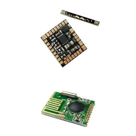
- 2x TLEopto Bausatz mit
THT-Bauteile zum Einlöten
- 4x Servokabel 20cm
Package contents
- 2x TLEopto kit with
THT components for soldering
- 4x servo cable 20cm
Technische Daten
- max. Eingangsspannung: 30V DC
- je Modul 2 getrennte Eingänge (Channel 1 & 2)
- einfache Verbindung mit Servokabel
- Abmessung (LxBxH): 23x20x9 mm
FichtelBahn
TLEopto
Erweiterung mit 4x galv. getrennte Eingänge für ReadyTLE
Das 2fach Modul ist für alle Anwendungen geeignet, bei dem Signale und Spannungen von den anzu-
schließenden Eingängen galvanisch getrennt werden müssen.
Mögliche Anwendungsbereiche für den TLEopto:
* isolierte Gleisbelegtmeldung im 3-Leitersystem z.B. für s88-Melder und ReadyTLE16
* Spannungsüberwachung von unterschiedlichen Fremdspannungen (AC und DC)
* Booster-Fahrstrom Überwachung
* Signaltrennung von unterschiedlichen Signalpegeln und Potenzialen (z.B. Arduino, Decodereingänge)
Besmmungsgemäßer Gebrauch:
Der TLEopto ist für den Einsatz im Modellbau, insbesondere in digitalen Modellbahnanlagen, entsprechend den
Besmmungen dieser Anleitung vorgesehen. Es handelt sich hierbei nicht um ein Spielzeug, sondern um
Modellbauarkel für Erwachsene. Jeder andere Gebrauch ist nicht besmmungsgemäß und führt zum Verlust der
Gewährleistung und des Garaneanspruchs.
Dieser Arkel ist nicht geeignet für Kinder unter 14 Jahren!
Designated Use:
The TLEopto is usage modelling, and especially digital model railways. It should be ed and used according to this
manual. This is not a toy, but a model building arcle for adults. Any other use is not in accordance with the intended
use and leads to the loss of the guarantee and the guarantee claim.
This product is not suitable for children under 14 years!
Technical data
- max. input voltage: 30V DC
- 2 separate inputs per module (channel 1 & 2)
- Simple connecon with servo cable
- Dimensions (LxWxH): 23x20x9 mm
2Stück im SET
2 Module mit je
2 Optokoppler
The twin module is applicable for all applicaons where signals and voltages must be electrically isolated from the
connected inputs..
Possible areas of applicaon for the TLEopto:
* Isolated track occupancy detecon in a third rail system, e.g. for s88 detectors and ReadyTLE16
* Voltage monitoring of dierent external voltages (AC and DC)
* Booster supply current monitoring
* Signal isolaon of dierent signal levels and potenals (e.g. Arduino, decoder inputs)

Anleitung TLEopto v1.0 © 2023 FichtelBahn
Version 1.1 Technische Änderungen und Irrtümer vorbehalten
manual TLEopto v1.0 © 2023 FichtelBahn
Version 1.1 Technical changes and errors reserved
Lötarbeiten am Bausatz:
Der TLEopto ist ein 2fach Optokoppler der gleichzeig für unter-
schiedliche Anwendungen verwendet werden kann. In der Abbildung
dargestellt als Rückmelder im 3-Leitersystem, bzw. als Sensor zur
Überwachung von Tastern und Fremdspannungen bis 30V AC/DC.
Die beiden Eingänge verfügen über anparallele Dioden, so dass die
Polarität keine Rolle spielt und eine AC-Spannung bzw. Fahrstrom vom
Booster verwendet werden kann.
Anschlussbeispiel „Belegtmeldung im 3-Leitersystem“:
Die beiden getrennten Ausgänge sind über 3-polige Sleisten
erreichbar, bei dem der milere Anschlusspin keine Funkon hat. Die
Baugruppe benögt auch keine Versorgungsspannung für den Betrieb.
Die beiden GND-Pins können gemeinsam oder getrennt mit dem
Melder verbunden werden. Die beiden Ausgänge haben eine
gemeinsamen GND und sind intern miteinander verbunden. Das
Ausgangssignal (OUT1 & 2) ist massebezogen und kann mit Melde-
eingängen verbunden werden, deren Zustandserfassung gegen Masse
erfolgt z.B. ReadyTLE16.
Eine ideale Verbindungsmöglichkeit ohne Schrauben und Löten, z.B.
mit dem ReadyTLE16, sind die beiliegenden Servokabel.
Der SMD bestückte Bausatz besteht aus 4 Bauteilen (2x Schraubklem-
men für die Eingänge und 2x Sleisten für die Ausgänge), die Sie
auf der Baugruppe einlöten müssen - siehe Anschlussskizze. Weitere
Arbeiten sind an der Baugruppe nicht notwendig!
2.CHA
1.CHA
TLEopto-Addon
GND
OUT 1
OUT 2
Zum EINGANG
z.B. ReadyTLE
AC/DC
5V-30V
INPUT
Taster / Masse / Signal
intern
intern
vom Booster
ŝŝͲ/ĚĞŶƟĨLJ
ĐƟǀŝƚLJ
Message
INPUT 0-7
5V
0 1 2 3 4 5 6
GND
7
INPUT 8-15
5V
8 9 10 11 12 13 14
GND
15
0 7 8 15
5V
GND
IN
FichtelBahn
2.CHA
1.CHA
TLEopto-Addon
2.CHA
1.CHA
TLEopto-Addon
Fahrstrom
vom Booster A
Anschluss z.B.
mit Servokabel
Fahrstrom
vom Booster B
Boosterbereich B Boosterbereich A
Der typische Anwendungsfall ist die Gleisbesetztmeldung im
3-Leiter-System in Verbindung mit dem ReadyTLE16. (16-fach Rück-
melder gegen Masse). Der TLEopto scha die galvanische Trennung
zwischen Fahrstrom und Melderpotenzial. Eine mögliche Anschluss-
skizze mit 4 Meldern und 2 getrennten Boosterkreisen sehen Sie
in der Abbildung. Die Verbindung vom TLEOpto zum ReadyTLE16
erfolgt einfach über die beiliegenden Servokabel.
TLEopto anschließen:
The SMD assembled kit consists of 4 components (2x screw terminals for
the inputs and 2x pin headers for the outputs), that must be soldered
onto the module - see connecon diagram. No further assembly is
required!
Soldering work on the kit:
The TLEopto is a twin optocoupler that can be used simultaneously for
dierent applicaons. The illustraon shows a feedback sensor in a third
rail system or a sensor for monitoring push-buons and external voltages
up to 30V AC/DC.
The two inputs have an-parallel diodes so that the polarity is irrelevant
and any AC voltage or tracon current from the booster can be used.
The two separate outputs are accessible via 3-pin pin headers,
where the middle connecon pin has no funcon. The module
does not require addional supply voltage for operaon.
The two GND pins can be used individually or connected as
common GND to the detector. The two outputs internally con-
nected to each other. The output signal (OUT1 & 2) is ground-
related and can be connected to signalling inputs whose status
is detected against ground, e.g. ReadyTLE16.
The enclosed servo cables are an easy to use connecon opon
without screws and soldering, e.g. with the ReadyTLE16.
Connect TLEopto:
Connecon example:
The typical applicaon is track occupancy detecon in a
3-track system in conjuncon with the ReadyTLE16.
(16-fold feedback to ground). The TLEopto provides galvanic
isolaon between the tracon supply and the detector
potenal. A possible connecon diagram with 4 detectors
and 2 separate booster circuits is shown in the schemac. The
connecon from the TLEopto to the ReadyTLE16 is easily done
by using the supplied servo cables.
This manual suits for next models
1
Other Fichtelbahn Control Unit manuals
