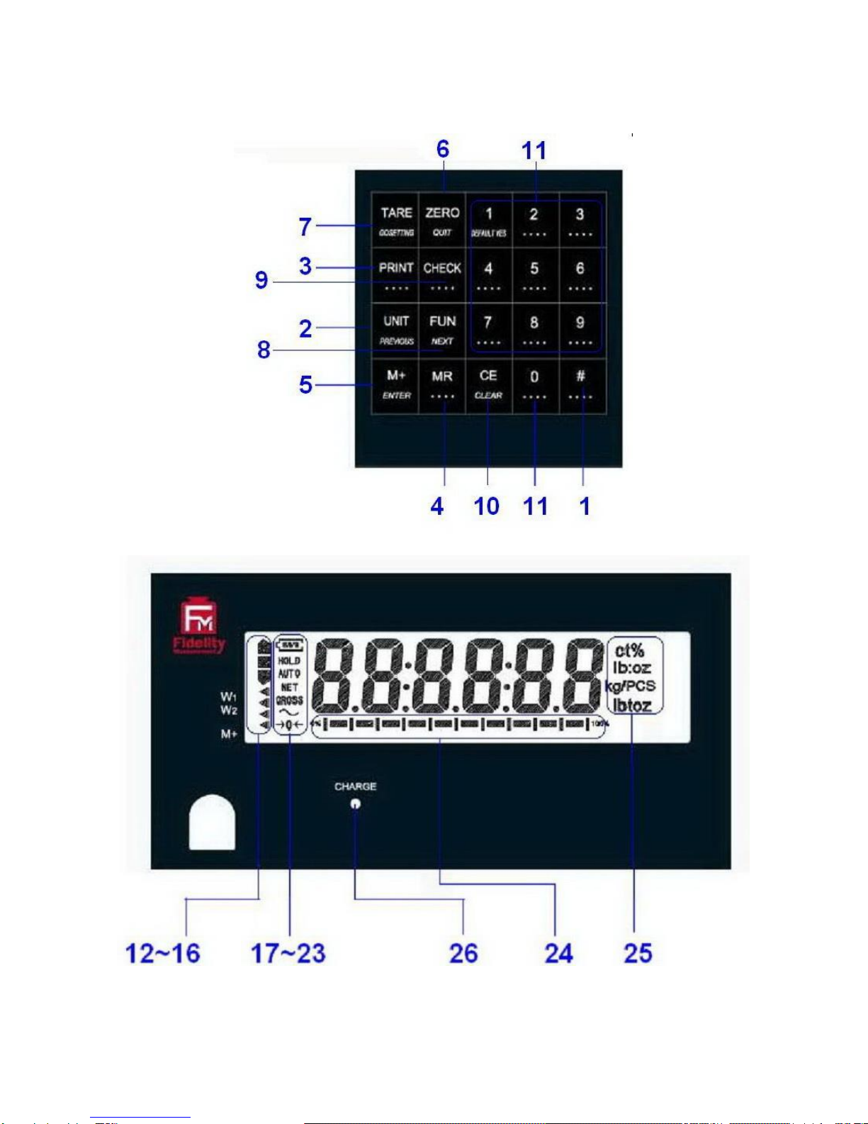
Fidelity Electronics DM-3000 User manual

DM SERIES
HIGH PRECISION WEIGHING SCALE
OPERATION MANUAL
PLEASE READ THIS MANUAL VERY CAREFULLY BEFORE
ATTEMPT TO OPERATE THIS SCALE
V118 June 2012
Specifications subject to change without prior notice


CONTENTS
1. INSTALLATION
2. SPECIFICATIONS
3. KEYS, DISPLAY AND CONNECTIONS
4. GETTING STARTED
5. INITIAL SETUP
6. INSTRUCTION FOR USE
7. RS232 DATA OUTPUT MODE
8. TICKET / RECEIPT PRINTING
9. LABEL PRINTING (LP-50 or CPOMPATIBLE)
10. BATTERY POWER AND RECHARGING
11. ERROR CODES
12. DAILY CARE AND MAINTENANCE
Appendix A: -
BI-DIRECTIONAL COMMUNICATION COMMANDS

1. INSTALLATION
Because of metrological legislation, installation/some
metrological parameter settings are limited to be done by
authorized personnel only. Do not attempt to change any of the
built-in parameters. Contact your dealer for installation and
technical assistance.
CAUTION:
This scale is legal for trade only when it is sealed (and/or
stamped) and bearing a serial number. Do not attempt to break
the seal (or stamp) affixed to this scale or remove the serial
number. Contact your dealer for more information and after
sales service.
For most accurate weighing result, do not use the unit in where
or when the environment condition falls beyond as those listed
on SPECIFICATIONS.
Do not attempt to open this scale or conduct any trouble
shootings other than those listed on TROUBLE SHOOTING.

2. SPECIFICATIONS
Model
Capacity [Max (g)]
Readability [d (g)]
W1
W2
d1
d2
DM-3000
3000
Nil
0.1
Nil
DM-3000D
1500
3000
0.1
0.2
DM-6000
6000
Nil
0.1
Nil
DM-6000D
3000
6000
0.1
0.2
DM-10K
10000
Nil
0.1
Nil
DM-10KD
5000
10000
0.1
0.2
DM-20K
20000
Nil
0.1
Nil
DM-20KD
10000
20000
0.1
0.2
Weight Units
kg / g / lb (Weight Unit Conversation Supports
Single Range Models only)
Tare Range
- Max (Subtractive Tare)
Platter
220 x 290mm all Stainless Steel
Dual Power Source
Built-in Rechargeable Battery, and
DC External Power Adaptor
Operation
Environment
15 ~ 35oC. Non-condensed. R.H.≦85%
Specifications subject to change prior to notice

3. KEYS, DISPLAY AND CONNECTIONS

1. SPARE
Spare key, no assignment.
2. UNIT KEY
Press this key to shift among various weight units (if weight unit
conversation is enabled).
3. PRINT KEY
1
Press this key to print the results to a computer or a printer through the
RS-232 output.
4. MR KEY
Press this key to recall total stored transactions.
5. M+ KEY
Press this key to accumulate current weight to memory manually.
6. ZERO KEY
Press this key to set weight displayed to zero when an empty scale has
drifted away from a true zero reading.
7. TARE KEY
Press this key to tare off the weight of a container.
8. FUNCTION KEY
Press this key to shift between percentage, piece count and animal
2
mode.
9. CHECK FUNCTION
Press this key to start check weighing function and to enter value for HI and
LO limit.
10. CE KEY
Press this key to clear value entered.
1
This key is also used to accumulate the current weight value to memory when F17 is set to
ON.
2
When F11 = ON.

11. NUMERIC KEYS
Numeric keys 0 ~ 9.
12. CHECK SYMBOLS
HI = Checked Value is higher than the HI limit entered,
OK = Checked Value is in between than the low and HI limits entered,
LO = Checked Value is lower than the LO limit entered.
13. W1INDICATOR
3
(When under dual weighing range mode
4
) Visible when this scale is in the
first weighing range (W1).
14. W2INDICATOR
5
(When under dual weighing range mode) Visible when this this scale is in
the second weighing range (W2).
15. SPARE
Blank, no function assigned.
16. M+ INDICATOR
Visible when the total accumulated weight value is being displayed.
17. BATTERY POWER / LEVEL INDICATOR
Visible to show: -
This scale is being powered by the built-in rechargeable battery,
Remaining battery level.
18. HOLD INDICATOR
(When under animal mode) Visible when weight reading being displayed is
a frozen value.
3
This indicator will not appear when this instrument is in single range mode.
4
This instrument can support two weighing ranges with different maximum capacities (Max)
and different scale intervals (d), each range extending from zero to its maximum capacity.
5
This indicator will not appear when thus unit is in single range mode.

19. AUTO INDICATOR
Visible when this scale is in animal weighing function.
20. NET INDICATOR
Visible when the tare function is in effect. Weight reading shown is net
value.
21. GROSS INDICATOR
Visible when gross weight reading is displayed.
22. STABLE INDICATOR
This indicator appears to indicate the weight detected is in stable condition.
23. ZERO INDICATOR
Visible when this scale is at true zero weight status.
24. CAPACITY TRACK BAR
The ratio (increment = 10%) of applied & remaining weighing capacities are
shown here.
25. WEIGHT UNITS AND FUNCTIONS
% = Percentage (when in Percentage Mode in function),
kg = kilogram,
PCS = Pieces (Piece Count Mode in function),
kg/PCS and g/PCS = Weight per piece (Piece Count Mode in
function),
lb = pound.
26. CHARGE STATUS INDICATOR
Red color: Recharging battery,
Green color: Charging completed.

BOTTOM VIEW
A. ON/OFF KEY
Press this key to turn this scale on or off.
B. DC JACK INPUT
External power adaptor is plugged in here.
Output requirements of the power adaptor: -
DC9 ~ 12V 800mA,
Polarity: - Any kind.
C. RS232 COMPORT (DB9)
RS232 communication comport.

4. GETTING STARTED
In order to obtain an accurate weighing result, this scale must be placed on
a strong and level surface. Avoid using this scale in environment where
excessive wind flow, vibration and extreme temperature change exist
General Warning: -
This scale is not an explosion proof device.
This scale is not a water proof device.
Do not open this scale, no user serviceable parts inside. Always
contact your dealer for service.
This scale not to be subject to shock, excessive vibration or
extremes of temperature (before or after installation).
4.1 BUILT-IN RECHARGEABLE BATTERY
This scale is equipped with a built-in rechargeable battery. Before first time
use, recharge it for at least 8 hours to ensure the best battery performance.
4.2 POWER ADAPTOR
Before plugging in the power adaptor, check and make sure the input
voltage of the adaptor matches with output voltage of the electricity outlet. If
not, contact your dealer immediately.
4.3 CONNECTING OTHER DEVICES
6
4.3.1 Before Connecting with others
Turn this scale off and cut off power before making any connections or
disconnections.
6
Turn this instrument off before making any connections or disconnections.

4.3.2. Connecting RS232 to computer
RS232 COMPORT
COM PORT ON COMPUTER
(DB9)
(DB25)
2 = RXD
3 = TXD
3 = TXD
3 = TXD
2 = RXD
2 = RXD
5 = GND
5 = GND
7 = GND
4.3.3 Connecting RS232 to Printer (DB25)
RS232 COMPORT (DB9) ON
SCALE
COMPUTER COM DB25
2 = RXD
3 = TXD
3 = TXD
2 = RXD
5 = GND
7 = GND
4.4 SETTING UP THE PREFERRED OPERATION PARAMETERS
Set all preferred operation parameters according to 5.4 INTERNAL
FUNCTION TABLE.
NOTE: -
1. F1~F26 are accessible without restriction,
2. F60~F66 are restricted functions which may request a password or
hardware key to access,
3. F80 ~ F99 are restricted functions which may request a password or
hardware key to access. These functions are usually for dealer and
authorized personnel only and all settings these functions are
monitored and recorded. Do not change any setting of these functions
to avoid operation errors.

5. INITIAL SETUP
5.1 INTERNAL SETTINGS
Application parameters can be checked or set through internal setting
functions. Refer to 5.4 for description of all internal functions.
5.2 HOW TO ENTER AND SELECT INTERNAL FUNCTION
Follow the below steps to enter and select desired parameter of an internal
function.
a. Turn this scale off and on again,
b. Press [TARE] during countdown,
c. Display F1,
d. This scale is now in internal function,
e. Quick access to a function number
Press 1 to go to F10,
Press 2 to go to F20,
Press 6 to go to F60 (for dealer and authorized personnel only),
Press 8 to go to F80 (for dealer and authorized personnel only),
Press 9 to go to F99 (for dealer and authorized personnel only),
Press 0 to go to F1,
5.3 KEY FUNCTION DURING INTERNAL FUNCTION MODE
[M+] = Enter, save and return,
[ZERO] = Quit without saving,
[FUN] = Go next,
[UNIT] = Go previous,
[CE] = Clear,
[TARE] = Go to internal function during power on countdown, or set
F1 value being shown to zero and to display the net
span gain by applying additional load applied.


6. INSTRUCTION FOR USE
6.1 POWER ON
Powered on this scale, it will: -
a. Display software number and revision (if any)
b. Display the calibration count value,
c. Display the parameter set count value,
d. Display all display segments,
e. This scale is now ready for operation.
6.2 START WEIGHING
a. If zero weight cannot be obtained when unloaded, press [ZERO]. After
[ZERO] is pressed, the ZERO INDICATOR will appear. Refer to
SPECIFICATIONS for maximum zero range,
b. Always place an object onto platform gently. Excessive force applied
to platform may cause damages to the weight sensor,
c. The weight of the object is displayed automatically,
d. It is a good practice to remove all loads from platform after weighing. It
will prolong the life of the weight sensor.
6.3 ABOUT WEIGH UNIT CONVERSION
The default weight unit is = kg. Depends on the internal settings, this scale
supports also g and lb.
6.3.1 Conversion between Metric Weight Units (kg and g)
When 3 or 4 decimal places (0.000 or 0.0000) is selected in F80, reading in
g is possible during normal operation by pressing [UNIT] disregarding to the
setting of F9.
The weight unit employed before power off will be employed when powered
on again.

6.3.2 Conversion between Metric (kg and/or g) and Imperial
7
(lb)
weight units (F9)
This scale supports conversion among kg, g and lb. To enable this
conversion function, set F9 = ON. Press [UNIT] to shift among various
weight units.
The weight unit employed before power off will be employed when powered
on again.
6.4 TARE OFF THE WEIGHT OF A CONTAINER
Tare function is used to temporarily set this scale to zero (such as
cancelling the weight of a box or a container) in order to get the net weight
result
6.4.1 Manual Tare
When a container is used, follow the below steps to tare off the weigh of it
and to get a net weight result.
a. Remove all loads from platform,
b. Make sure that the ZERO INDICATOR is on. If not, press [ZERO],
c. Place container on platform,
d. Press [TARE] ,
e. NET INDICATOR appears to indicator tare is in effect and weight
displayed display is net weight. Refer to SPECIFICATIONS for
maximum tare range,
f. To cancel tare effect, remove all loads from platform and press
[TARE],
g. NET INDICATOR disappears. GROSS INDICATOR appears to
indicator tare effect has been removed and weight displayed display is
gross weight.
6.4.2 Auto Tare
8
(F12)
If this function is enabled, this scale will assume the first stable weight
applied is a container and will tare off the weight of it automatically.
7
To comply with the laws of certain countries and approval requirements, the imperial
weight unit may be disabled. Contact your dealer for more information.
8
Set F12 = ON to enableAuto Tare Function
This manual suits for next models
7
Table of contents
Other Fidelity Electronics Scale manuals