Fieldbus Specialists Profibus User manual

MCD 3000 – PROFIBUS GATEWAY
MCD 3000 SERIES 1 USER MANUAL
PROFIBUS Gateway
for MCD 3000 Series Soft Starters
P/N FS-1135
User Manual
Ver. 1.9
10 October 2003
© Copyright 2002 Fieldbus Specialists

MCD 3000 – PROFIBUS GATEWAY
MCD 3000 SERIES 2 USER MANUAL
REVISION NOTES
Index
Date
Chapte
r
Author
Rev.
Revision note
1
04-Feb-2002
All
AMcN
1.0
Created
2
11-Feb-2002
All
AJ
1.1
Various corrections
3
10-Mar-2002
All
AJ
1.2
Extended indications for invalid PROFIBUS
address
4
14-Mar-2002
2.6.2, 7
AJ
1.3
Local/Remote setting recommendations,
corrections to Specifications
5
4-April-2002
2.6.1
AKJ
1.4
Wiring diagrams added, mapping of read
memory corrected
6
5-MAY-2002
All
AmcN,
AJ
1.5
Unified format, added functions to handle
comm. breakdown
7
25-OCT-2002
AJ
1.6
Added comments related to Siemens S7
PLC
8
1-OCT-2003
JP
1.7
Added comments re. firmware version 2.02
and code compliance with Danfoss
manual AMB00000 Rev. G
9
9-OCT-2003
JP/AJ
1.8
Modified to reflect compliance with
AMB00000 Rev. G
10
10-OCT-2003
JP
1.9
Note re.byte sequencing in 2.10
TECHNICAL SUPPORT
In case of any questions or problems, please contact Fieldbus Specialists on
We will endeavour to reply immediately.
PREFACE

MCD 3000 – PROFIBUS GATEWAY
MCD 3000 SERIES 3 USER MANUAL
The data and illustrations in this manual are not binding.
Fieldbus Specialists reserve the right to modify our products in
line with our policy of continuous product development. The
information in this manual is subject to change without notice
and should not be considered as a commitment by Fieldbus
Specialists.
Fieldbus Specialists assume no responsibility for any errors that
may appear in this document.
Although this product has been developed with great care
and extensively tested, Fieldbus Specialists cannot guarantee
the suitability of this product for any purpose. Warranty claims
shall be limited to the right to require rectification of faults.
Liability for any damages, which may have arisen from the use
of this product or its documentation, shall be limited to cases of
intent.

MCD 3000 – PROFIBUS GATEWAY
MCD 3000 SERIES 4 USER MANUAL
CONTENTS
1 INTRODUCTION ............................................................................................................................. 6
1.1 IMPORTANT USER INFORMATION............................................................................................................... 6
1.2 GENERAL.................................................................................................................................................. 6
2 INSTALING THE GATEWAY ..........................................................................................................8
2.1 GATEWAY CONNECTION DIAGRAM............................................................................................................ 8
2.2 FRONT PANEL ........................................................................................................................................... 9
2.3 INSTALLATION SEQUENCE....................................................................................................................... 11
2.4 POWER CONNECTION .............................................................................................................................. 11
2.5 PROFIBUS CONNECTION....................................................................................................................... 12
2.5.1 Cabling..........................................................................................................................................12
2.5.2 GATEWAY CONFIGURATION ................................................................................................................... 13
2.6 MCD3000 CONNECTION......................................................................................................................... 14
2.6.1 Cabling..........................................................................................................................................14
2.6.2 MCD3000 configuration .............................................................................................................16
3 PROGRAMMING THE MASTER CONTROLLER ........................................................................ 18
3.1 GSD FILE................................................................................................................................................ 18
3.2 DECLARING MODULES ............................................................................................................................ 18
3.3 SETTING PROFIBUS PARAMETERS........................................................................................................ 19
3.4 MASTER-SLAVE DATA EXCHANGE .......................................................................................................... 21
3.5 DATA WRITE AREA.................................................................................................................................. 21
3.6 DATA READ AREA................................................................................................................................... 22
3.7 ISSUING COMMANDS .............................................................................................................................. 24
4 OPERATION OF THE GATEWAY ................................................................................................ 29
4.1 SCANNING SLAVES.................................................................................................................................. 29
4.2 SCANNING TIMES .................................................................................................................................... 29
4.3 OFFLINE SLAVES..................................................................................................................................... 31
5 SPECIFICATIONS......................................................................................................................... 32
6 TROUBLESHOOTING .................................................................................................................. 33

MCD 3000 – PROFIBUS GATEWAY
MCD 3000 SERIES 5 USER MANUAL
Table List
Table 1 – LED Indication.......................................................................................................................................10
Table 2 – PROFIBUS socket pin assignment .......................................................................................................12
Table 3 – RS-485 pin assignment.........................................................................................................................14
Table 4 – MCD 3000 Local/Remote modes ..........................................................................................................17
Table 5 – MCD 3000, RS-485 baud rate values....................................................................................................17
Table 6 – MCD 3000 node address on RS-485 network.......................................................................................17
Table 7 – Gateway parameter, RS-485 link baud rate..........................................................................................19
Table 8 – Gateway parameter, gateway operation on communication loss..........................................................20
Table 9 – PROFIBUS Write / Out Memory in control module................................................................................22
Table 10 – Command result codes .......................................................................................................................22
Table 11 – PROFIBUS Read / In memory.............................................................................................................24
Table 12 – Valid commands..................................................................................................................................25
Table 13 – New Command / Command Acknowledge handshaking ....................................................................27
Table 14 – Result Ready / Result Acknowledge handshaking..............................................................................27
Table 15 – Scanning cycle length for different baud rates and the number of MCD 3000 devices present..........30
Table 16 – Maximum time to detect return of an offline device.............................................................................30
Table 17 – Gateway specifications........................................................................................................................32
Table 18 – Troubleshooting guide.........................................................................................................................33
Figure List
Figure 1. Typical diagram of a PROFIBUS network, a gateway and an RS-485 sub-network...............................8
Figure 2. Gateway front panel................................................................................................................................9
Figure 3. Entering address via dip switches, an example....................................................................................13
Figure 4. Recommended wiring diagram for one MCD3000 device.....................................................................15
Figure 5. Wiring diagram for a number of MCD3000 devices connected to a single gateway.............................15

MCD 3000 – PROFIBUS GATEWAY
MCD 3000 SERIES 6 USER MANUAL
1INTRODUCTION
1.1 Important user information
This manual describes operation and programming of a
PROFIBUS gateway for MCD3000 series soft starters, gateway
firmware revision 2.11.
Gateway with firmware version 2.11 complies with MCD3000
protocol as described in Danfoss manual AMB00000 Rev. G
and is likely to be incompatible with earlier versions of the soft
starter. Remote programming of parameters is not supported
at the moment. Contact Fieldbus Specialists if you require a
firmware version that supports earlier models.
Observe all the necessary safety precautions when controlling
any MCD 3000 series device over the serial communications
link, including alerting personnel that the machinery may start
without warning.
1.2 General
The MCD 3000 series of solid state soft starters incorporate a
serial communications facility that allows for the remote
control and interrogation of the MCD 3000 from an intelligent
host (master) via a multi-drop RS-485 communications network
using a proprietary protocol, specific to MCD 3000 devices.
The RS-485 link may be used to interface a MCD 3000 device to
a PROFIBUS network using the PROFIBUS to MCD 3000 gateway.
The PROFIBUS Master can then control any connected MCD
3000 device – start it, stop, reset trip conditions and read
operational status, motor conditions or trip status.
The PROFIBUS to MCD 3000 Gateway is a certified PROFIBUS
slave device. A number of gateways and other PROFIBUS
slave devices can be connected to the same network, subject
only to standard PROFIBUS limitations.
The gateway is a master on the RS-485 multi-drop MCD 3000
communications network. Up to 30 MCD 3000 devices may be
connected to a single Gateway. In this way up to 30 MCD
3000 devices will share one PROFIBUS address on the PROFIBUS
communications network.
This manual describes how the PROFIBUS to MCD 3000
gateway operates, how to connect MCD 3000 series soft
starters to the gateway and how to connect and operate the
gateway on a PROFIBUS network.

MCD 3000 – PROFIBUS GATEWAY
MCD 3000 SERIES 7 USER MANUAL
When reading this manual, it may help to refer to the MCD
3000 Operating Instructions, Danfoss document no. AMB00000.

MCD 3000 – PROFIBUS GATEWAY
MCD 3000 SERIES 8 USER MANUAL
2INSTALING THE GATEWAY
2.1 Gateway connection diagram
The diagram below shows how the gateway is connected to
the PROFIBUS network and to the RS-485 sub-network.
PROFIBUS DP
Master
DP Slave DP Slave
MCD 3000
Gateway
MCD 3000
device MCD 3000
device
MCD 3000
device
MCD 3000
device
PROFIBUS network
RS-485 sub-network
Figure 1. Typical diagram of a PROFIBUS network, a gateway
and an RS-485 sub-network.
A gateway can coexist with a number of other PROFIBUS
nodes, including other gateways. Each gateway constitutes a
single PROFIBUS node, even if it connects to a number of MCD
3000 devices.

MCD 3000 – PROFIBUS GATEWAY
MCD 3000 SERIES 9 USER MANUAL
2.2 Front panel
Figure 2. Gateway front panel
Fig. 2 shows the front panel of the gateway. Located on the
front panel are:
1. RS-485 sub-network connector for connecting up to 30
MCD 3000 devices, DB9, male,
2. PROFIBUS network connector, DB9, female,
3. Power connector, 2 pin removable terminal block,
4. Bi-colour PROFIBUS status LED,
5. Bi-colour RS-485 status LED,
6. Dip switches for PROFIBUS address selection.
The following table indicates the status of the PROFIBUS
connection.
RS485
STATUS 1
ON
2345678
ADDRESS
LSB
24V DC
_
+
MCD 3000 - PROFIBUS Gateway
FS-1135
PROFIBUS
PROFIBUS
STATUS
1
5
6
3
4
2
RS485
POWER
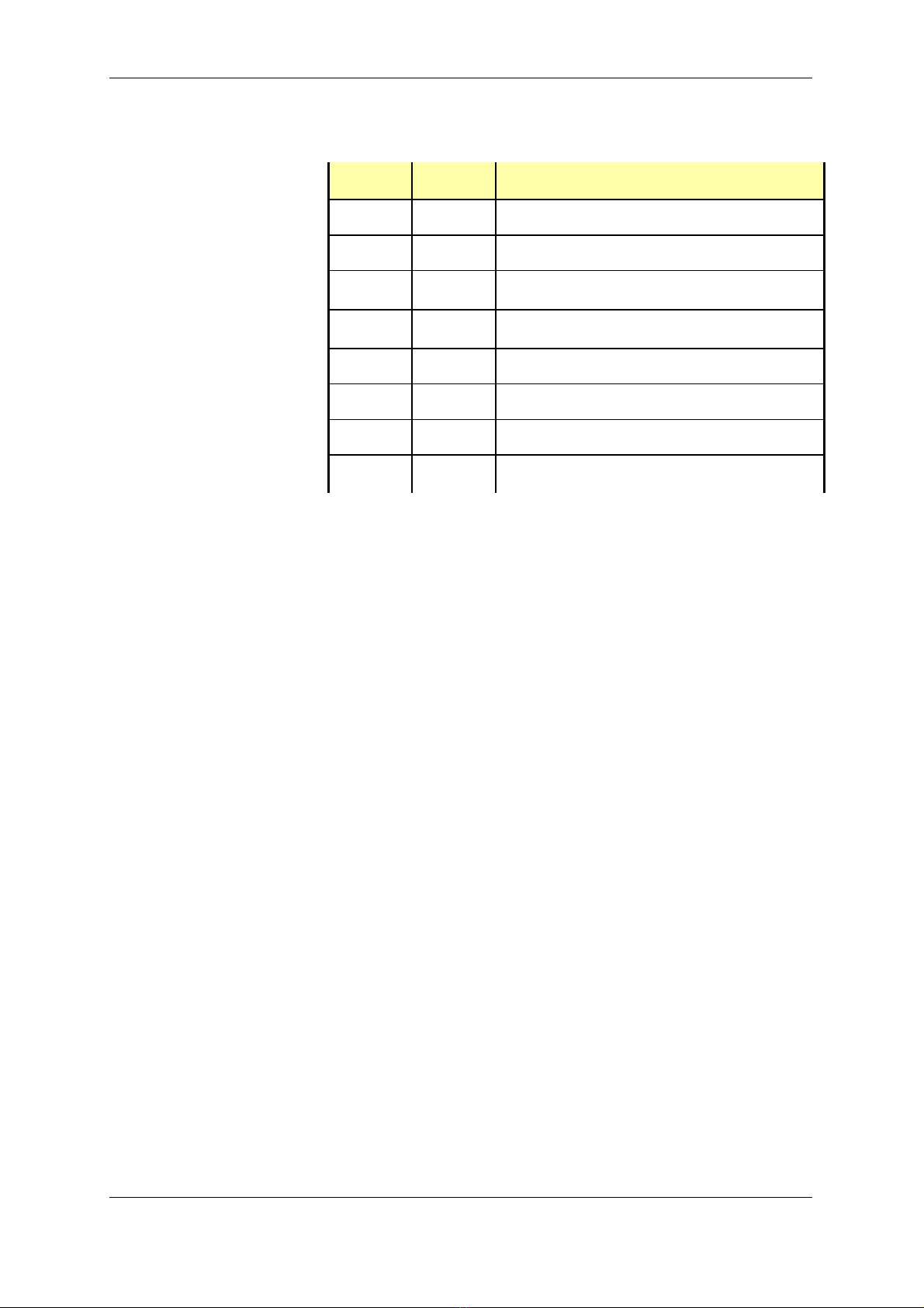
MCD 3000 – PROFIBUS GATEWAY
MCD 3000 SERIES 10 USER MANUAL
PROFIBUS
LED
RS-485
LED
Gateway status
Gateway starting (max. 6 sec) or no power
ANY
Invalid PROFIBUS address
ANY
PROFIBUS link down – no PROFIBUS Master,
incorrect address or no connection,
ANY
PROFIBUS link error – wrong configuration or
parameter in Master
ANY
PROFIBUS link up and problem-free
ANY
No communication on the RS-485 link
ANY
Occasional errors on the RS-485 link
Both PROFIBUS and RS-485 links operational
and error-free
Legend:
- LED off
- LED steady green
- LED flashing red/off
-LED flashing green/red
-LED flashing green/red/off
ANY – applies irrespective of LED status
Table 1 – LED Indication
These simple rules may be worth remembering:
-Flashing indicates errors on the relevant link,
-Flashing red means that the gateway attempts to
communicate but fails every time,
-Flashing red/green means that the gateway can
communicate, but errors occur.
R/B
B
B
B
G
G
G
G
G/R
G/R
G/R/B
R/B
R/B
R/B
G/R/B

MCD 3000 – PROFIBUS GATEWAY
MCD 3000 SERIES 11 USER MANUAL
2.3 Installation sequence
When installing the gateway, we recommend the following
sequence:
!Connect power, see section 2.4 for details. If there are no
indications of power, check voltage and polarity.
!Set the PROFIBUS address on dip switches, configure and
activate PROFIBUS master, see section 2.5 for instructions.
Configure the PROFIBUS master for one MCD device only.
On success the PROFIBUS status LED will go green, on error
it will blink red. If the LED stays red, check the cable,
address on the gateway and address setting in the
master. If the LED flashes green/red, verify the
configuration of modules in the PROFIBUS master. Do not
proceed further until you get the PROFIBUS LED steady
green.
!Configure and connect the first MCD 3000 device, set it to
address 1, see section 2.6 for details. On success, the RS-
485 status LED should go green. We recommend initially
to configure PROFIBUS master for only one MCD device
connected to the gateway and to get this configuration
working successfully. Later on you can increase the
number of MCDs. If the RS-485 status LED stays solid red,
check the RS-485 cable, the MCD 3000 device
configuration (set to Local), wiring to MCD 3000 and the
value of the PROFIBUS parameter in the gateway
configuration data in PROFIBUS master – RS-485 sub-
network baud rate setting.
!Configure and connect the remaining MCD 3000 devices,
make also the relevant changes to the configuration of
PROFIBUS master. On success the RS-485 LED should go
solid green. If it flashes green/red, one or more MCD 3000
does not communicate with the gateway.
2.4 Power connection
The gateway requires 24V DC power, approx. 130mA. The
voltage can be unregulated – the gateway will operate
correctly for power voltage in the range 12-32V. The current
drawn changes with voltage – it is ~240mA for 12V and ~90mA
for 32V. The power connector is a removable terminal block,
2-pin. The device is reverse polarity protected – in the case of
reversed connection it will not get damaged but it will not
operate either.
MCD 3000 – PROFIBUS GATEWAY
MCD 3000 SERIES 12 USER MANUAL
Presence of correct power can be verified by looking at the
LEDs on the front panel – at least one LED should be illuminated
at all times, whether green or red.
2.5 PROFIBUS connection
The PROFIBUS socket of the PROFIBUS to MCD 3000 Gateway
must be connected to a PROFIBUS network in accordance
with PROFIBUS Technical Guideline “Installation Guideline for
PROFIBUS DP/FMS”, PROFIBUS International Order No. 2.112.
2.5.1 Cabling
The PROFIBUS to MCD 3000 Gateway connection requires a
PROFIBUS cable with DB9, male connector. Pin assignment in
the PROFIBUS socket is as follows:
DB9 socket Pin
Purpose
1
Shield/functional ground
2
Not connected
3
RXD/TXD-P (Data Line)
4
Not connected
5
Data ground (reference potential for VP)
6
VP – supply voltage, +5V
7
Not connected
8
RXD/TXD-N (Data Line, Inverted)
9
Not connected
Table 2 – PROFIBUS socket pin assignment
Pins 3 (RXD/TXD-P) and 8 (RXD/TXD-N) must be connected. The
other pins can be used, if needed.
The gateway does not provide termination on the PROFIBUS
cable. If the gateway is located at either end of the cable,
the termination resistors should be provided externally, usually
in a PROFIBUS plug with the termination option. The gateway
provides termination power on pins 5 and 6.
The shield on the PROFIBUS socket is galvanically connected to
the metal top lid on the enclosure. An earthing lug is provided
for earthing the top lid. When the PROFIBUS cable plug is in the

MCD 3000 – PROFIBUS GATEWAY
MCD 3000 SERIES 13 USER MANUAL
socket, the shield on the PROFIBUS cable is connected with the
socket shield, the top lid and the earthing lug.
2.5.2 Gateway configuration
The gateway automatically detects the baud rate for the
PROFIBUS network. All standard baud rates are supported as
per PROFIBUS Specification, up to 12 Mbits/s.
The PROFIBUS node address of the PROFIBUS to MCD 3000
Gateway is configured with an 8-way DIP switch that is located
on the front panel of the gateway. The address must be set to
a value that is not in use by any other device on the PROFIBUS
network. Valid address range – 0 to 125.
The procedure for setting the node address of the gateway is
as follows:
!Ensure that the device is not powered up by unplugging
the power connector.
!Set the DIP switches to the desired value (see figure
below).
!Reinsert the power connector
Fig. 1 shows the location of the DIP switches on the front panel.
These switches are used to enter the address, with the most
significant bit on the left and the least significant bit on the
right. The address is entered in binary, with the switch in up
position for ‘0’ and in the switch in the down position for ‘1’.
For example, to set the address “3”, binary 0000 0011, the
switches need to be positioned as follows.
1
ON
2345678
ADDRESS
LSB
Figure 3. Entering address via dip switches, an example
In addition to setting the address, it is necessary to define the
gateway’s configuration in the PROFIBUS Master. For detailed
description of this important stage, refer to section 3.

MCD 3000 – PROFIBUS GATEWAY
MCD 3000 SERIES 14 USER MANUAL
2.6 MCD3000 connection
2.6.1 Cabling
The MCD 3000 devices should be connected to the RS-485
serial sub-network as per the MCD 3000 Operating Instructions.
The gateway is connected to the RS-485 sub-network using a 9
pin male DB connector, located to the left side of the
enclosure. Pin assignment is as the following table indicates.
Pins not listed there are unused or reserved and MUST NOT be
connected.
Pin Number
Purpose
1
+ Signal
5
Shield/Ground
9
- Signal
Table 3 – RS-485 pin assignment
We recommend using a shielded twisted pair cable. When the
gateway is located away form the soft starter, the
communications cable should be shielded and should not be
run in the vicinity of high current power cabling. It is advisable
to fit termination resistors at each end of the cable to match its
characteristic impedance, typically in the range of 100-120
ohm.
The recommended connection diagram is shown in fig. 4
below. We recommend connecting cable shield on the
gateway side only and we recommend that the connection
point 61 on the MCD3000 device be left unconnected.

MCD 3000 – PROFIBUS GATEWAY
MCD 3000 SERIES 15 USER MANUAL
69
61
68
SERIAL COMM.
PORT RS485
to pin 5
to pin 9
to pin 1
cable shield
RS485
+
GND
_
MCD3000 device Gateway
Figure 4. Recommended wiring diagram for one MCD3000
device.
to pin 5
to pin 9
to pin 1
69
_
61
68
+
GND
MCD3000
69
_
61
68
+
GND
MCD3000
69
_
61
68
+
GND
MCD3000
FS-1135
gateway
Figure 5. Wiring diagram for a number of MCD3000 devices
connected to a single gateway

MCD 3000 – PROFIBUS GATEWAY
MCD 3000 SERIES 16 USER MANUAL
If a number of MCD3000 devices are connected to a single
gateway, we recommend wiring them in series, see fig. 5. The
cable should constitute a single line, without side branches.
Note that we recommend connecting GND points (61) on all
MCD 3000 devices to guarantee that they share the same
ground potential. If the devices are connected to the
common ground in some other way (ex. via a metallic
mounting), it may not be necessary to connect points 61.
RS-485 interface on MCD3000 is not galvanically isolated.
Failure to equalize ground potential on MCD 3000 devices
connected via RS-485 link may result in their damage.
2.6.2 MCD3000 configuration
The gateway can communicate at any of the baud rates that
MCD 3000 devices can support. All MCD 3000 devices
connected to the same sub-network must be configured for
the same baud rate.
Each MCD 3000 device must be configured with a node
address. Each must have a different address and each
address must be in the range 1 to the number of MCD 3000
devices connected to the gateway, inclusive. Example: if four
devices are connected to a gateway, they must have
addresses 1, 2, 3 and 4.
Each MCD 3000 Local/Remote Mode parameter (Parameter
20) must be set to 0, 1 or 2. Setting this parameter to 3 disables
the RS-485 communications port. For more detailed
explanation refer to the MCD 3000 Operating Instructions.
MCD 3000 devices must be set for “Local” operation using the
Local/Remote pushbutton on the front panel. When this is
done, the LED labeled “REMOTE” on the front panel is off.
NOTE: When the MCD3000 device is set for “Remote”, it does
not execute commands received over the RS-485 link.
However, it still acknowledges these commands.
Consequently, the gateway and the PROFIBUS master cannot
detect this condition. For working with a gateway, we
recommend to set Local/Remote Mode parameter (Parameter
20) to 2 – “Local control only”. This will eliminate the possibility
of the MCD3000 device being set for “Remote” accidentally or
by mistake.
The MCD 3000 devices must be configured using the keypad/
LCD display on its front panel. The method of setting

MCD 3000 – PROFIBUS GATEWAY
MCD 3000 SERIES 17 USER MANUAL
parameters is described in details in the MCD 3000 Series Soft
Starter Operating Instructions.
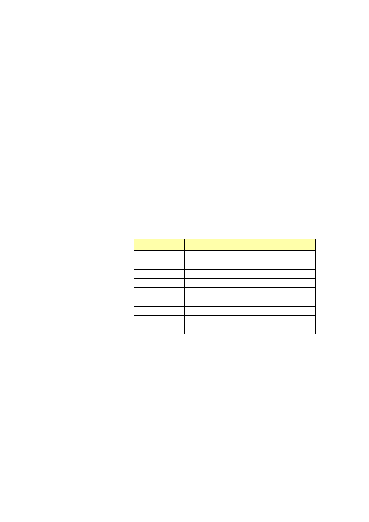
The following tables show the required configuration for the
MCD 3000 soft starter parameters relevant to the operation of
the gateway.
Parameter 20 Local/Remote Mode
Configuration Options
0
Local/Remote enabled
1
Local/Remote enabled
only when motor stopped
2
Local control only
3
Remote control only
Default Setting
0
Local/Remote enabled
Table 4 – MCD 3000 Local/Remote modes
Parameter 22
Serial communication baud rate
Configuration Options
1
1200 baud
2
2400 baud
3
4800 baud
4
9600 baud
5
19200 baud
Default Setting
4
9600 baud
Table 5 – MCD 3000, RS-485 baud rate values
Parameter 23
MCD 3000 address for RS-485 serial
communications
Configuration Options
1 – 99
Required Setting
A number between 1 and the total
number of MCD 3000 devices on the
network
Table 6 – MCD 3000 node address on RS-485 network

MCD 3000 – PROFIBUS GATEWAY
MCD 3000 SERIES 18 USER MANUAL
3PROGRAMMING THE MASTER CONTROLLER
3.1 GSD file
Information on the technical characteristics of the gateway is
loaded into PROFIBUS master software by means of a GSD file.
A floppy disk with the GSD file is supplied with the gateway. The
GSD file name is “FS1135.GSD”. Follow the instructions in the
PROFIBUS configuration/management software manual for
loading the GSD file and adding the new slave, the gateway,
to the network.
If you need a copy of the GSD file, please contact us at
sales@fieldbus.com.au.
For the PROFIBUS Master to communicate with the gateway, it
must be provided with information about the way that the
gateway works. You can do it by following these steps:
!load the GSD file, for details refer to the manual for
master configuration software,
!declare the required modules within the gateway,
!set PROFIBUS parameters of the gateway.
3.2 Declaring modules
The gateway is a modular PROFIBUS slave, consisting of several
modules as defined in the GSD file. The gateway must be
configured with the control module declared first, and then
with one slave module declared for each soft starter
connected to it.
The control module has 10 bytes of input data and 3 bytes of
output data, no consistency. This module is declared in the
GSD file with the “Preset” keyword and many configuration
applications will automatically declare it as required and in the
correct position – as the first module in the configuration.
Check that the software you are using supports the “Preset”
keyword and if not, declare this module manually as the first
one in the configuration data of the gateway.
In addition to the control module, you must declare a slave
module (5 Bytes In, module consistency) for each MCD 3000
device connected to the gateway. The gateway assumes

MCD 3000 – PROFIBUS GATEWAY
MCD 3000 SERIES 19 USER MANUAL
that the addresses of the MCD 3000 devices start at 1 and are
consecutive, up to the number of expected devices.
The first motor starter module relates to the MCD 3000 with
address 1, the second one to 2 and so on. Address values are
not related to physical positioning of MCD 3000 devices on the
RS-485 sub-network.
NOTE for users of SIMATIC S7:
Motor starter modules are defined as so called “modules with
data consistency”. This is necessary to guarantee accuracy of
current reading. The consequence of it in S7 is that module
data cannot be read directly – direct reading always returns 0.
Instead, you should use SFC14 to cyclically copy module data
to PLC internal memory and then retrieve the required values.
In case of problems consult an S7 expert re. the memory
addresses to be used for motor starter modules and the correct
way of retrieving module data.
3.3 Setting PROFIBUS parameters
The gateway requires three parameters, associated with the
control module in the gateway configuration. The first
parameter defines the desired baud rate on the RS-485
network. The gateway supports all the baud rates that the
MCD 3000 devices support:
First Parameter
Value
Baud Rate
1
1,200 bps
2
2,400 bps
3
4,800 bps
4
9,600 bps (Default)
5
19,200 bps
Table 7 – Gateway parameter, RS-485 link baud rate

MCD 3000 – PROFIBUS GATEWAY
MCD 3000 SERIES 20 USER MANUAL
The second parameter defines gateway operation if
communication with the master stops:
Second
parameter
Action on communication
breakdown
1
Stop polling MCD3000
devices
2
STOP command sent to all
MCD3000 devices
3
COAST TO STOP sent to all
devices
Table 8 – Gateway parameter, gateway operation on
communication loss
The selected action will be executed when the gateway had
established initial communication with the master and
subsequently this communication stops.
If the second parameter is set to 1, the gateway will stop
poling MCD3000 devices on communications breakdown. This
may cause MCD3000 devices to trip, if they are so
programmed (Parameter 24). For other values of this
parameter, the gateway will keep on polling and will prevent
MCD3000 tripping.
The third parameter defines the timeout, in seconds, for
communication with the master.
If the gateway stays off-line on PROFIBUS for the time period as
set in the third parameter, the gateway will take action as
defined by the second parameter. Allowed range is 0 to 255.
Default value is 5, setting the timeout at 5 sec. If the third
parameter is set to 0, no timeout supervision will be carried out
and once communication with master commences, the
gateway will keep on polling MCD3000 devices irrespective of
the status of gateway-master link.
On receiving an invalid parameter value or invalid
configuration data from the PROFIBUS master, the gateway
goes offline and flashes the PROFIBUS status LED green, red and
then turns it off. After a few seconds the PROFIBUS master will
try again to set the gateway to ONLINE state and the cycle
repeats until the error is corrected.
Table of contents
Popular Gateway manuals by other brands


Philio Technology Corporation
Philio Technology Corporation PSC03 user manual

Dell
Dell Dell Edge Gateway 3002 Specifications

Genexis
Genexis DRG 7000-Series installation guide

TRI02SYS
TRI02SYS EnOcean 02LINE Installation and operating manual

Juniper
Juniper SRX1500 How to set up

XiNCOM
XiNCOM Twin WAN XC-DPG503 user guide