Fiilex Matrix II RGBW User manual

User Manual
FLXMXRGBW
190102A2
RGBW

1
General Notes
Basic Operation (refer to Parts Diagram on following page)
• Powering On
The Matrix II RGBW power adapter includes an AC plug for power input and a 3-pin XLR connec-
tor for output. To supply the fixture with power, insert the XLR connector into the Power Input
(19) and connect the AC plug into an active wall socket. The fixture’s OLED Display (9) will turn
on once it is receiving power. The On/Off Switch (12) can toggle the fixture’s output on and off.
Settings can still be adjusted while the switch is set to off.
• Mounting
The Matrix II RGBW’s Baby/Junior Pin (5) can be mounted to baby or junior receivers. Secure the
fixture to pins with the Mount Tightening Knob (6). Remove the Mount Tightening Knob when
mounting to juinor receivers.
• Adjusting the Tilt
Use the Yoke Tightening Handle (8) to lock the fixture’s tilt position.
• DMX Interface
The Matrix II RGBW receives DMX signals via its 5-pin XLR ports. When a DMX signal is detected
the fixture will automatically enter DMX Mode and all manual controls will be deactivated. To
indicate DMX Mode, the OLED Display (9) will replace the word “LOCAL” with the DMX address.
• DMX/RDM Support
The Matrix II RGBW is compatible with DMX/RDM (Remote Device
Management) protocol. With RDM, the DMX address of the fixture
can be changed remotely via the DMX signal.
• USB Interface
The Matrix II RGBW is equipped with a Mini USB Port (11) for updating firmware. The standard
USB Port (17) provides 5V 1A power for wireless DMX antennas. Please register your product at
www.fiilex.com to be informed when firmware updates are available.
• The Matrix II RGBW has been designed for professional studio and location applications and may
only be operated by qualified persons.
• Please read the following operating instructions very carefully before using this fixture.
• For your own safety, please follow all safety instructions and warnings.
• Keep these operating instructions for future reference.
• For further information, contact Fiilex ([email protected]) or your retailer.
Mode
Manual LOCAL
DMX
###
DMX
Description
Screen
Indicator
Directly adjust the fixture’s output via control knobs. Use the
On/Off Switch to turn light on or off. Settings can still be adjust-
ed while the switch is off.
Control via DMX. Manual control knobs become disabled. DMX
Mode activates automatically when signal is detected.
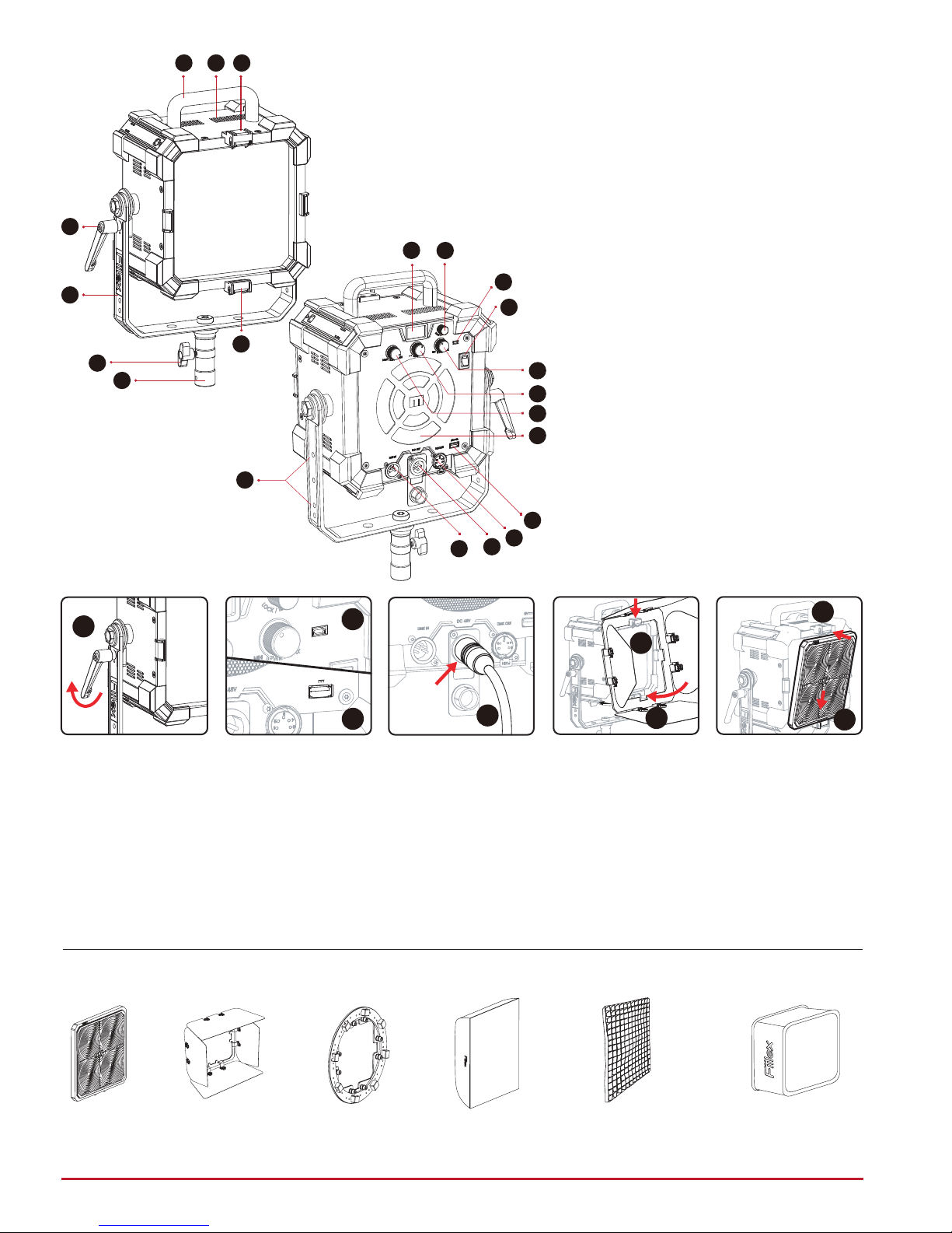
Parts Diagram
Compatible Accessories
2
1.
2.
3.
4.
5.
6.
7.
8.
9.
10.
11.
12.
13.
14.
15.
16.
17.
18.
19.
20.
21.
Outer Bracket
Mounting
Barndoor and Speed
Ring accessories
mount by hanging
upper indent over Top
Accessory Latch (3)
then pushing lower
indent into Bottom
Accessory Latch (4).
Turning the Light On
Insert the XLR 3-Pin
connector into the
Power Input (19).
Plug the AC connec-
tor into a wall socket.
USB Interface
The Matrix II is
equipped with a Mini
USB Port (11) for
updating firmware, as
well as a standard USB
Port (17) with 5V 1A
power for wireless
DMX antennas.
Adjusting the Matrix II
Use the Yoke Tight-
ening Handle (8)
to lock the fixture’s
tilt position.
Inner Bracket
Mounting
Top Handle
Heat Exhaust Vent
Top Accessory Latch
Bottom Accessory Latch
Baby/Junior Pin
Mount Tightening Knob
Yoke
Yoke Tightening Handle
OLED Display
Lock/Menu Dial
Mini USB Port (firmware update)
On/Off Switch
Intensity Dial
Gain/Saturation Dial
CCT/Hue Dial
Fan Intake Vent
USB Port (5V 1A power)
DMX Output
(5-Pin XLR-Female)
Power Input Port (XLR 3-Pin)
DMX Input (5-Pin XLR Male)
Power Adapter Mounting Points
1 2 3
4
5
9
11
10
12
13
7
6
14
15
16
17
18
19
20
21
8
Matrix
Barndoor
Matrix
Speed Ring
Matrix
Softbox
Matrix
Pop-Up Softbox
Grid for Matrix
Softbox
Matrix
Fresnel
8
5V 1A
11
17 19
3
4
3
4
Mount the Fresnel
accessory by placing
its lower indent into
the Bottom Accesso-
ry Latch (4). Then
push the top of
Fresnel into the Top
Accessory Latch (3).
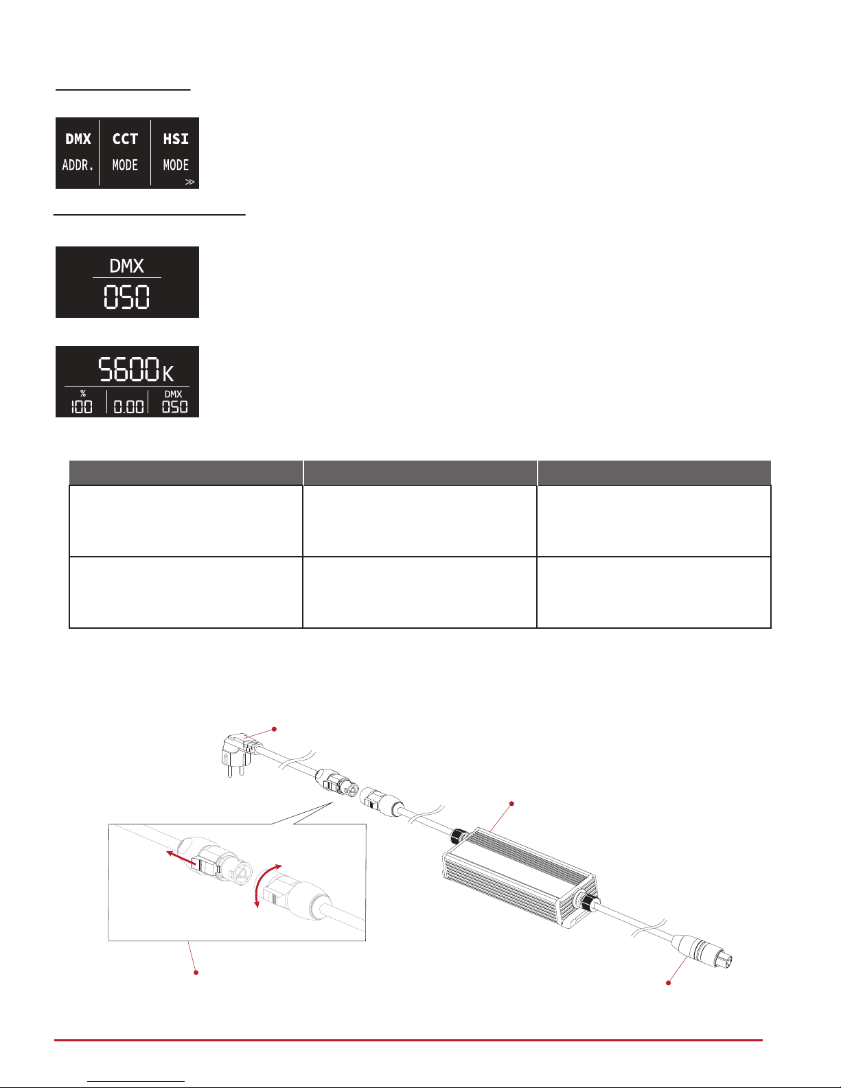
Rear Panel Interface Operation
3
Assigning DMX Address:
DMX Address Setting Screen
Main Screen with DMX Mode Active
1. Double click the Lock/Menu Dial (10) and scroll all the way to the left
to unlock the DMX address setting screen on the OLED Display.
2. Rotate the knob to select the desired base address (1-510).
3. Lock in setting by clicking knob once. Alternatively, the address will
automatically lock in after 1 second of inactivity.
4. The Matrix II RGBW occupies a variable amount of DMX channels
depending on mode. When a DMX address is selected, the Matrix II
RGBW will automatically assign the other addresses in a consecutive
manner. Below is a table containing two of the fixture’s modes and
their respective DMX channel order.
• For adjusting fixture’s DMX address via RDM, consult operating instruc-
tions for DMX/RDM control system.
Mode
1. Intensity
2. CCT
3. Green/Magenta
DMX Channels
CCT
HSI
1. Intensity
2. Hue (color wheel)
3. Saturation
Description
Tunable White
360º Color Wheel
*For information on other modes and their DMX channels, visit us at www.fiilex.com
Changing Modes: 1. Double click the Lock/Menu Dial (10).
2. With the same dial, scroll left or right for the desired mode.
3. Once desired mode is highlighted, click the dial once to access it.
• Each mode has its own controls, display, and dial(s).
• For the lastest information on new modes and their DMX chan-
nels, register your fixture at www.fiilex.com.
Connect AC Power Adapter to AC Cable (For regions outside of the U.S)
Pull lock
unlock
AC Cable (Plug head varies by region: EU, UK, AU, ZA, CH)
320W/48V Power Adapter
XLR 3-Pin Connector (DC out)
powerCON TRUE1
P/N: 5048669-001 (female)
5048669-002 (male) P/N: 5048659-001 (female)
First Page of Mode Panel

4
Specifications
CCT Range
Light Engine
Power Draw
DC Input
AC Input
Power Port
DMX Ports
Weight
Size (L x W x H)
Mount Style
Thermal Design
Operating Temperature
IP Rating
LED Lifetime
Certifications
2800 - 10000K Continuous Tuning
(Four) Dense Matrix LED
340W Max
48V (300W DC Max)
100 - 240V AC, 50 ~ 60Hz
XLR-3P
XLR-5P (In & Out)
Fixture & Yoke: 9.7lbs / 4.4kg | Power Adapter 5.6lbs / 2.6kg
6.7in x 12.2in x 16.5in / 17.1cm x 31.0cm x 41.1cm
Baby Stud 5/8” Female (16mm) & Junior Stud 1-1/8“ Male (28mm)
Advanced Vapor Cooling System (Fan Cooled)
32 - 104ºF / 0 - 40ºC
IP-24
42,000 hours
FCC
Option 1: Attach Power Adapter to Clamp
Mounting the Power Supply
Option 2: Attach Power Adapter to the Yoke

5
• CAUTION! High intensity output! - Do NOT look directly into light source.
• DO NOT point the light at combustible or flammable materials.
• DO NOT attempt to disassemble the body of the Matrix II RGBW. Doing so will void the
warranty.
• DO NOT cover/block fixture’s air vents.
• Use only a soft, dry towel to gently clean the exterior of the light.
• DO NOT lift or suspend the light by the power cable.
• DO NOT use the Matrix II RGBW or accessories if they display any physical damage.
• BEFORE first use, make sure to remove all protective membranes.
• DO NOT mount the Matrix II RGBW in a hanging position without a separate safety cable.
• Only use Fiilex approved accessorie for the Matrix II RGBW.
1689 Regatta Blvd. Richmond, CA 94804
www.fiilex.com
Safety
Warranty
Unless otherwise stated, your product is covered by a one year parts and labor limited warranty.
Fiilex guarantees, to the original buyer, that this product is to be free of defects in both workman-
ship and material for a period of one year from the date of shipment. This warranty extends to all
products which have proved defective through normal use but excludes products that have been
disassembled, modified or misused by the buyer or any other person. This warranty is in lieu of all
other warranties, and disclaims all warranties expressed or implied, including any warranty of mer-
chantability, fitness for a particular purpose, or arising from the course of dealing between the
parties or usage of trade.
Returning an Item Under Warranty for Repair
It is necessary to obtain a Return Authorization Number (RA#) from your dealer/ point of purchase
BEFORE any units are returned for repair. Fiilex will make the final determination as to whether or
not the unit is covered by warranty. Fiilex will replace or repair to proper working condition any
products that are returned under warranty. Products repaired or replaced under warranty are
under warranty only for the remaining unexpired period of time of the original warranty.
Any Product unit or part returned to Fiilex must be packaged in a suitable manner to ensure the
protection of such Product unit or parts. The package must be clearly and prominently marked to
indicate that the package contains returned product units or parts with a Return Authorization
(RA#) number. All returned product units or parts must be accompanied by a written explanation of
the alleged problem or malfunction.
Other manuals for Matrix II RGBW
1
This manual suits for next models
1
Table of contents
Other Fiilex Dj Equipment manuals

Fiilex
Fiilex P360 GEen II Series User manual

Fiilex
Fiilex Q1000 II User manual

Fiilex
Fiilex Q5 COLOR User manual

Fiilex
Fiilex Q500 User manual

Fiilex
Fiilex C360 Series User manual

Fiilex
Fiilex P180 User manual

Fiilex
Fiilex Q8 Junior User manual

Fiilex
Fiilex Matrix II Turnable White User manual

Fiilex
Fiilex P180E User manual

Fiilex
Fiilex T360 Series User manual


