Safety Instructions
User Guide
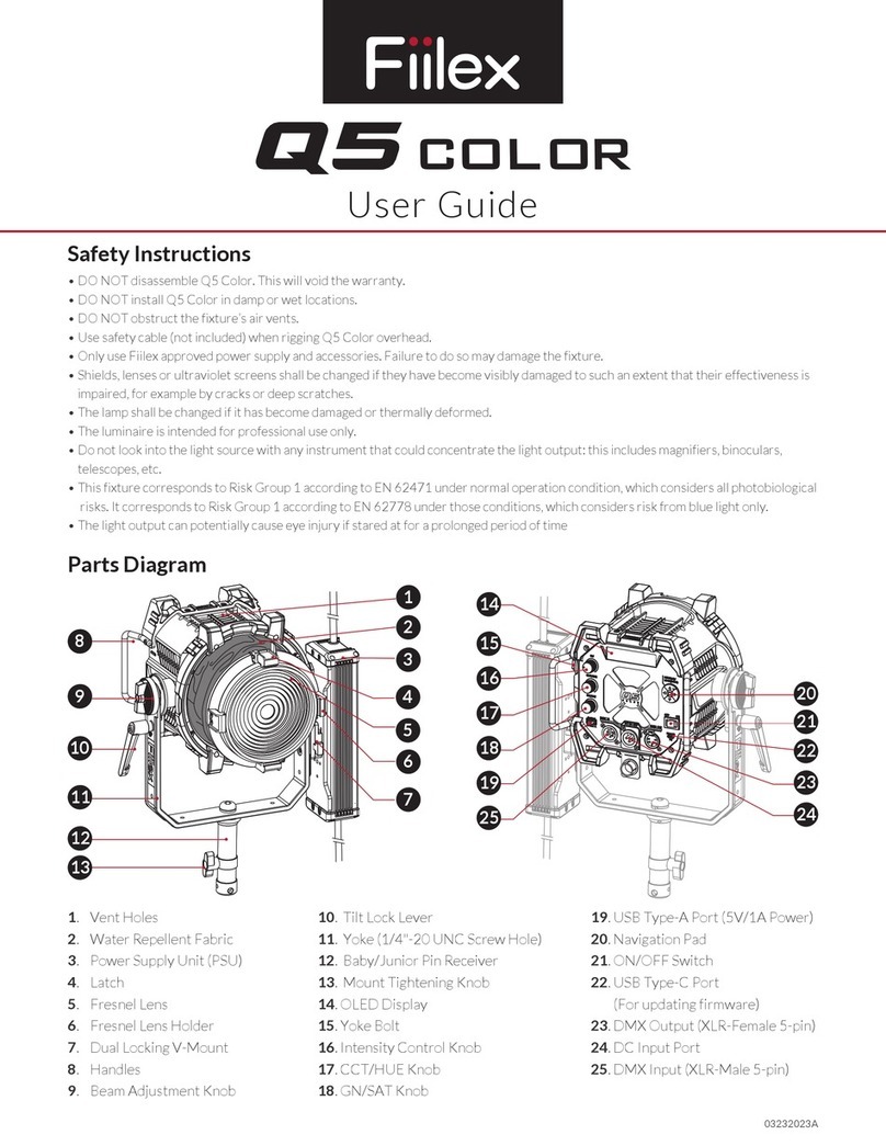
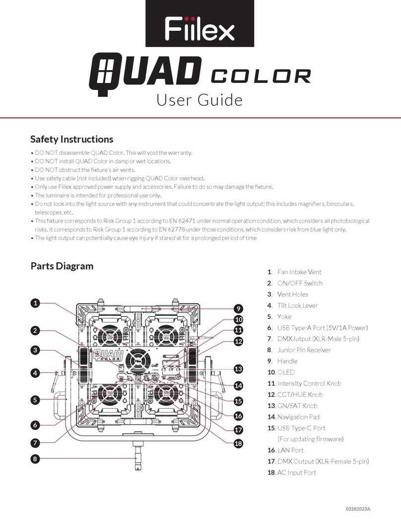
Parts Diagram
• DO NOT look into the light source. Be cautious of the high-intensity beam.
• DO NOT disassemble T360/T365. This will void the warranty.
• DO NOT install T360/T365 in damp or wet locations.
• DO NOT obstruct the fixture’s air vents.
• DO NOT cut any track sections.
• DO NOT install any part of the track system (use with Eutrac 233/225 track system only) less than 5 feet from the floor.
• DO NOT install T360/T365 less than 6 inches from any curtain or combustible materials.
• DO NOT energize anything other than T360/T365 on the track.
• DO NOT connect any power tools, extension cords and appliances to the track. This is to avoid a risk of fire and electric shock.
• DO NOT connect a track to more than one branch circuit unless the track is constructed to be used with more than one
branch circuit. This is to prevent a dangerous overload of the neutral and a risk of fire.
• Disconnect electrical power before changing the track layout.
• T360/T365 should be replaced when its light source (not replaceable) reaches its end of life.
• Please seek installation assistance from qualified electricians if needed.
• Only use Fiilex approved power supply and accessories. Failure to do so may damage the fixture.
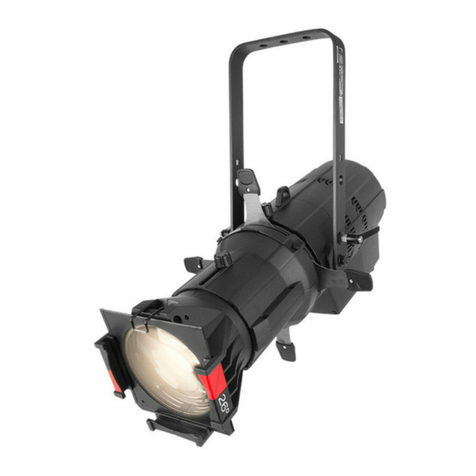
T360 / T365
1. Eutrac Multi-Adapter
2. Power Module Box
3. Side Vents
4. Barndoor Lock
5. Yoke Knob
6. Magnetic Accessory Lock
7. Barndoor Slot
8. 5” Fresnel Zoom Lens (T365 only)
9. Lens Tighten Knobs (T365 only)
10. Barndoor Lock (T365 only)
11. Barndoor Slot (T365 only)
12. Barndoor Lock Release
13. Yoke
14. CCT / HUE Knob
15. On / Off Button
16. OLED Display
17. Intensity / DMX Knob
18. Rear Vents
9
811
10 12
13
15
16
17
18
14
2
14
5
6
7
3
210224A

