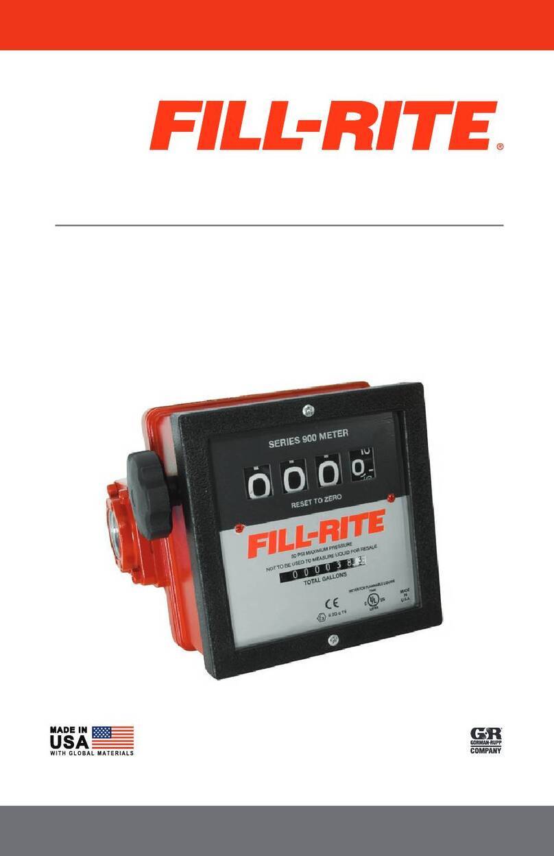
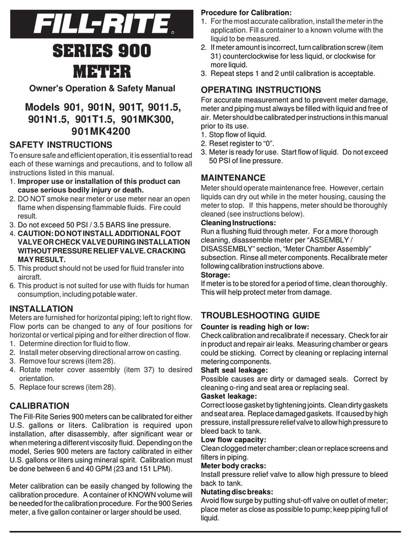
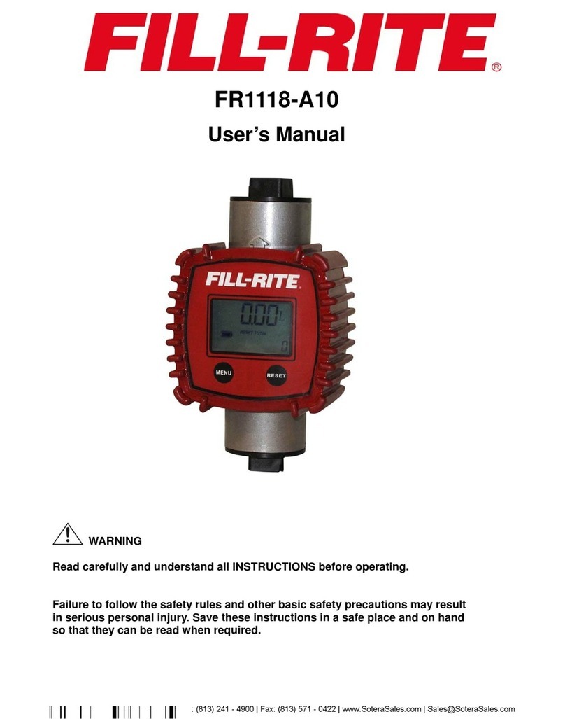
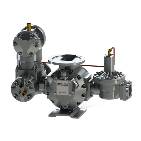
FILL-RITE 900DB Use and care manual

1
Digital Liquid Meter
Series 900 – High Flow
Models
900DB, 900DB1.5, 900DBBSPT, 900DB1.5BSPT
Owners Installation, Operation, and Safety Manual
Tuthill Corporation 8825 Aviation Drive Ft. Wayne, IN 46809 (260) 747-7529 www.tuthill.com

2
IMPORTANT! These boxes contain information that illustrates a point that may
save time or may be key to proper operation, or clarifies a step.
Table of Contents
Owners Installation, Operation, and Safety Manual.............................................................. 1
Table of Contents.................................................................................................................. 2
Thank You!............................................................................................................................ 2
About This Manual ................................................................................................................ 2
Safety Information ................................................................................................................. 3
Installation ............................................................................................................................. 3
Procedure for Meter Calibration ............................................................................................ 4
Operating Instructions ........................................................................................................... 5
Low Battery Warning............................................................................................................. 6
Storage.................................................................................................................................. 6
Troubleshooting .................................................................................................................... 6
Fluid Compatibility................................................................................................................. 7
Assembly and Disassembly .................................................................................................. 7
Illumination ............................................................................................................................ 8
Repair.................................................................................................................................... 8
Safety Testing Approvals ...................................................................................................... 8
Replacement Parts Information............................................................................................. 9
Thank You!
Thank you for your purchase of the Fill-Rite 900 Series Digital Meter! Your Fill-Rite
product comes with over 80 years of fluid transfer experience behind it, providing you the
value that comes with superior performance, user friendly design, long service life, and
solid, simple engineering. Experience that gives you peace of mind.
Excellence at Work. Excellence in Life
About This Manual
From initial concept and design through its final production, your Fill-Rite meter is built to
give you years of trouble free use. To insure it provides that service, it is critical that you
read this entire manual prior to attempting to install or operate your new meter.
Become familiar with the terms and diagrams, and pay close attention to the highlighted
areas with the following labels:
`
At Fill-Rite, your satisfaction with our products is paramount to us. If you have questions or
need assistance with your product, please contact us at 1-800-634-2695 (M-F 8 AM–5 PM
ET).
CAUTION! Failure to observe a “Caution” can cause damage to the equipment.
WARNING! Emphasizes an area in which personal injury or even death could
result from failure to follow instructions properly. Mechanical damage may also
occur.
®

3
Safety Information
Installation
Meters are furnished for horizontal piping with left to right flow
(facing the front of the meter). The display can be rotated to any
of four positions for horizontal or vertical piping and for either
direction of flow.
1. Determine direction for fluid to flow.
2. Install meter observing directional arrow on casting on
back of meter (circled). Liquid MUST flow in the direction of the arrow for proper
operation.
3. Once the meter is plumbed into place, remove
four screws (circled) on corners of meter face
(Torx T25 bit required).
4. Rotate meter face assembly to desired
orientation.
5. Replace four screws.
6. Complete installation by making sure the joints
are properly sealed and meter is positioned for
easy viewing and use.
WARNING! This product shall not be used to transfer fluids into any type of
aircraft.
WARNING! This product is not suited for use with fluids intended for human or
animal consumption or fluids containing water. Nickel plated meters are approved
for use with non-potable water, antifreeze, certain agricultural chemicals, and
other s
p
ecialized water a
pp
lications.
WARNING! To insure safe and proper operation of your equipment, it is critical to
read and adhere to all of the following safety warnings and precautions. Improper
installation or use of this product can cause serious bodily injury or death!
1) NEVER smoke near the meter, or use the meter near open flames when
metering a flammable liquid! Fire can result!
2) A “Fill-Rite” Filter should be used on the meter outlet to insure no foreign
material is transferred to the fuel tank.
3) Threaded pipe joints and connections should be sealed with the appropriate
sealant or sealant tape to minimize the possibility of leaks.
4) Storage tanks should be securely anchored to prevent shifting or tipping
when full or empty.
5) To minimize static electricity build up, use only static wire conductive hose
when metering flammable fluids, and keep the fill nozzle in contact with the
container being filled during the filling process.
6) DO NOT exceed 50 psi/ 3.5 BARS line pressure.
7) DO NOT install additional foot valve or check valve without a pressure relief
valve; otherwise the meter may rupture.
CAUTION! Threaded pipe joints and connections should be sealed with the
appropriate sealant or sealant tape to prevent the possibility of leaks.
Flow Direction

4
Totalize
r
Meter Calibration
Meter calibration is required upon installation, after disassembly, after significant wear, or
when dispensing a different viscosity fluid. Calibration must be done between 6 and 40
GPM (23 and 151 LPM). Meter calibration can be easily changed by following the
calibration procedure. A container of KNOWN volume will be needed for the calibration
procedure. For the 900 series digital meter, a five gallon container or larger, or a 20 liter
container or larger should be used.
Procedure for Meter Calibration
Unit of measure and calibration is configured using a 3-step process.
1) Select the desired unit of measure
2) Fill a container with a known volume using the desired fluid.
3) Enter the amount of fluid dispensed.
Prior to calibration, the unit must be placed in calibration mode. Simultaneously press and
hold the CAL and TOTAL buttons for 5 seconds to enter Calibration Mode.
1) The unit will default to the last unit
of measure used.
2) Press and release the TOTAL
button to toggle through the
available units of measure.
3) Press and hold the CAL button for 2
seconds to move to the next step.
4) If the meter is left untouched for 2
minutes or the RESET button is
pressed, the unit will automatically
exit Calibration Mode and ignore
any changes in volume.
1) CAL 2 will be displayed.
2) Begin dispensing fluid into the container.
3) FILL will begin to blink after fluid flow is detected.
4) Dispense the desired amount fluid; stop flow as soon as desired level is reached.
5) Press and hold the CAL button for 2 seconds to move to the next step.
IMPORTANT! If you have purchased this meter as part
of a “Kit”, the meter flange base is drilled with 4 holes.
This allows the meter to be used with 300 and 700
series pumps. Line the meter bracket up for installation
and insert the bolts in the two holes that align with the
corresponding holes on the pump outlet. Once the
meter bracket is bolted securely in place install the two
plugs in the holes that were not used to prevent
moisture from entering them.
IMPORTANT! When calibrating, the totalizers will not increase in value.
IMPORTANT! Dispensing into a container with a known volume allows the unit
to automatically calculate the internal scaling value to compensate for fluid
viscosities and the system flow rate.
IMPORTANT! If left untouched for 2 minutes, or the RESET button is pressed,
the meter will exit Calibration Mode and any dispensed fluid will be ignored.

5
1) Pressing and holding the CAL
button for 2 seconds before
dispensing into a container will
cause the meter to skip a fill
operation and only change the
unit of measure.
1) The left-most digit will begin
blinking.
2) Use the TOTAL button to scroll from 0 to 9 until the desired number has been
selected.
3) Press and release the CAL
button to move to the next digit.
4) Repeat Steps 2 - 4 until the
amount of dispensed fluid has
been entered.
5) If you make a mistake entering a
digit, press and release the CAL
button repeatedly until the digit
is active again.
6) Press and hold the CAL button
for 2 seconds to complete the
calibration process regardless of
the current digit selected.
7) If at the last digit and the CAL
button is pressed for less than 2 seconds, the process should roll back to the left-most
digit, but retain the current value. This allows the user to edit an incorrect value.
8) An error check for gross calibration errors (+/- 15%) will be performed unless USER
units are selected. If an error is detected, the meter will display Err0 until a button is
pressed and the calibration process is aborted.
9) If the meter is left untouched for 2 minutes or the RESET button is pressed, the unit
will automatically exit Calibration Mode and ignore any changes.
Operating Instructions
For accurate measurement and to
prevent meter damage, dispenser and
piping must always be filled with liquid
and be free of air. The meter portion of
your dispenser should be calibrated per
instructions in this manual prior to its
use.
The Fill-Rite 900 Series Digital Meter
face incorporates three buttons that
control all the operation and calibration
functions.
To turn the display on, or wake the
meter from “Sleep” mode, simply press
any button on the face. The display will
turn on and you can proceed with the
function you desire. Dispensing fluid will also turn the meter display on.
IMPORTANT! For maximum
accuracy, try to get as close as
possible to the dispensed
volume without changing flow
rate.

6
The last count and selected totalizer is retained and displayed when the meter is
turned on.
Pressing and releasing the TOTAL button will switch between the resettable and non-
resettable totalizers. (The R icon will be displayed when the resettable total is
displayed).
Pressing and holding the RESET button for 2 seconds will reset the counter.
Pressing and holding the RESET button and TOTAL buttons for 2 seconds will reset
the totalizer. The resettable totalizer must be active in order to reset it.
Pressing and holding the RESET button and CAL buttons for 2 seconds will display
the software version for 2 seconds and then perform a segment check for 3 seconds,
and then restore the display.
Pressing and holding the CAL button for 5 seconds will place the meter into a deep
sleep mode. Pressing any button twice will bring the meter out of deep sleep mode.
After 30 seconds of inactivity, the display will blank to conserve battery power.
If the meter is connected to the external power source, the display will not blank
unless forced into deep sleep mode.
If external power is removed, the meter will revert to battery only operating
characteristics and vice-versa.
The counter and totalizer 2 can be reset even if fluid flow is detected. The meter will
continue counting during the 2 second RESET button press, then reset to 0, then
resume counting.
Low Battery Warning
The digital display includes a “Low Battery”
warning indicator. When the battery reaches a
level low enough to require replacement, the
display will show “BAT” as a reminder to change
the battery. When necessary, replace batteries
per procedure on page 7.
Storage
If your meter is to be stored for a period of time, clean it thoroughly. This will help protect
the meter from possible damage.
Troubleshooting
The following troubleshooting guide is designed to help you with basic digital diagnostics
and repairs if you should encounter abnormal service from your 900 series meter. We
recommend you use only genuine Fill-Rite parts. These parts, and additional service
information is available through your authorized Fill-Rite dealer.
IMPORTANT! When the meter is in the “Deep Sleep” mode, dispensing fluid
will NOT turn the meter on. The meter will not display or accumulate any fluid
that is dispensed while in “Deep Sleep” mode.
IMPORTANT! “Deep Sleep” mode is designed to maintain a status of
operational readiness while offering battery conservation. The meter should
be placed in this mode when:
Flushing the unit so the dispensed volume is not counted.
Traveling over rough surfaces (off-road) where fluid is being jostled and
you don’t want volume from the motion to be counted.
Extending battery life; there is no penalty for repeatedly placing it in deep
sleep.

7
Further troubleshooting information can be found in your pump manual. If you need
additional assistance, please contact us at 1-800-634-2695 (M-F 8 AM–5 PM ET).
Concern Possible Cause Recommended Repair
Counter inaccurate. Meter mis-calibrated. Check calibration and recalibrate as
necessary (directions on page 4).
Air in lines or metering
chamber.
Check line seals and joints for
leakage; seal leaks appropriately.
Measuring disc is
sticking.
Clean or replace internal metering
components as necessary.
Low flow capacity. Clogged meter
chamber.
Clean meter chamber; clean or
replace screens and filters in piping.
Meter body cracks. Excess line pressure. Install pressure relief valve to allow
high pressure to bleed back to the
tank. Replace meter.
Nutating Disc Broken. Sudden high pressure
fluid hitting disc.
Avoid surge flows by installing a shut-
off valve on outlet of meter; install
meter as close to the pump as
possible, keep piping full of liquid.
Replace meter chamber assembly.
Fluid Compatibility
The 900DB series meter IS compatible with the following fluids:
Diesel Fuel Bio-Diesel (up to B20) Mineral Spirits Heptane Hexane Gasoline, E15
The 900DB series meter IS NOT compatible with the following fluids:
Bleach Hydrochloric Acid Ink Sulfuric Acid Salt Water
Assembly and Disassembly
The 900 Series Digital Meter consists of a chamber housing, measuring chamber, drive
shaft, digital counter assembly, and cover. The design of the meter is such that it can be
completely disassembled without disturbing the piping (refer to diagram on page 9 for item
number parts).
Accessing the Battery
For access to the batteries (2 AA batteries) (figure 1):
1) Remove the four screws at the top and bottom of the front
bezel (Torx #T25).
2) Lift bezel off. Batteries
are located on the back
side of the display; use a
Phillips head screwdriver
to remove the cover
screws to access the
batteries.
3) Reassemble by
reversing this procedure.
CAUTION! If in doubt about compatibility of a specific fluid, contact supplier of
fluid to check for any adverse reactions to the following wetted materials:
Aluminum Stainless Steel Fluorocarbon Buna N Polyester Nickel Acetal
Figure 1

8
WARNING! To reduce the risk of ignition of a flammable explosive atmosphere,
batteries MUST be chan
g
ed ONLY in a location known to be non-hazardous.
WARNING! To reduce the risk of explosion DO NOT mix old batteries with new
batteries
,
or mix batteries of different manufacturers.
WARNING! Batteries may ONLY be replaced with the following:
Duracell MN1500
Duracell MX1500
Energizer E91
Meter Chamber Assembly
The Meter Chamber consists of upper and lower chambers, a
nutating disc, and four screws (figure 2).
1) To expose the meter chamber assembly and seal remove
the 4 screws.
2) The meter chamber can be dislodged by removing the 4
screws (see figure 2).
Reassemble by reversing this procedure.
Repair
Meters needing repairs should be taken to an authorized repair facility. Meters MUST be
triple rinsed before taking them in for repairs.
Safety Testing Approvals
The Fill-Rite 900DB series meters have been tested for compliance to the standards set
forth by Underwriters Laboratories (UL), UL Canada, ATEX, and other testing
organizations. To determine which specific compliances apply to your particular
meter, refer to the faceplate for information and compliance logos.
IMPORTANT! When returning a meter for service, it must be triple rinsed and
accompanied by a note stating what chemicals have been pumped through it.
Meters not adhering to these specifications may be refused for service.
IMPORTANT! If replacing any components of the meter chamber, the
complete assembly must be replaced due to its precision method of
construction. This will assure a proper fit, and correct operation of the
chamber.
Figure 2

9
Replacement Parts Information
Replacement parts can be obtained through any authorized Fill-Rite dealer. Be sure to use
only genuine Fill-Rite replacement parts for your service and maintenance needs.
Models 900DB, 900DB1.5, 900DBBSPT, 900DB1.5BSPT
900 Series Digital Meter Replacement Parts Kit
Kit Number # Description Qty
900DBKT
1 Required Seal 3
2 Required Fasteners 6
3 Magnetic Driver 1
4 Chamber Assembly 1
KIT900PF
Meter to Pump
Flange Kit

10
Electrical Installation Information
Internal Power (Battery Power)
All 900DB Series Digital Meters are battery powered. The meter is equipped with a battery
tray located behind the faceplate on the circuit board itself. Power on these units is
supplied by two alkaline “AA” batteries. With normal use, these batteries should provide 2
– 4 years of use. The digital display contains an integral warning of low battery level (see
page 6 for details). If there are questions regarding appropriate replacement batteries for
your meter, please contact your Fill-Rite Customer Service Technical Support
Representative at 1-800-634-2695 (M-F 8 AM–5 PM ET). Incorrect battery selection may
void UL certification.
Tuthill Product Warranty
Tuthill Transfer Systems (“Manufacturer”) warrants each consumer buyer of its Fill-Rite
products (“Buyer”) from the date of invoice or sales receipt, that goods of its manufacture
(“Goods”) shall be free from defects of materials and workmanship. Duration of the
warranty is as follows:
Heavy Duty Products – Two Years
Manufacturers sole obligation under the foregoing warranties will be limited to either – at
Manufacturers option – repairing or replacing defective goods (subject to limitations
hereinafter provided) or refunding the purchase price for such Goods theretofore paid by
the buyer, and Buyers exclusive remedy for breach of any such warranties will be
enforcement of such obligations of the Manufacturer. If the Manufacturer so requests the
return of such Goods, the Goods will be redelivered to the manufacturer in accordance with
Manufacturers instructions FOB Factory. The remedies contained herein shall constitute
the sole recourse of the Buyer against the Manufacturer for breach of warranty. IN NO
EVENT SHALL THE MANUFACTURER’S LIABILITY FOR ANY CLAIM FOR DAMAGES
ARISING OUT OF THE MANUFACTURE, SALE, DELIVERY, OR USE OF THE GOODS
EXCEED THE PURCHASE PRICE. The foregoing warranties will not extend to goods
subject to misuse, neglect, accident, improper installation or maintenance, or have been
repaired by anyone other than the Manufacturer or its authorized representative. THE
FOREGOING WARRANTIES ARE EXCLUSIVE AND IN LIEU OF ALL OTHER
WARRANTIES OF MERCHANTABILITY, FITNESS FOR PURPOSE OF ANY OTHER
TYPE, WHETHER EXPRESSED OR IMPLIED. No person may vary the forgoing
warranties or remedies, except in writing signed by a duly authorized officer of the
Manufacturer. The Buyer’s acceptance of delivery of the Goods constitutes acceptance of
the foregoing warranties and remedies, and all conditions and limitations thereof.
Tuthill Corporation recommends you retain your sales receipt as proof of purchase.
WARNING! To reduce the risk of explosion DO NOT mix old batteries with
new batteries
,
or mix batteries of different manufacturers.
WARNING! Batteries may ONLY be replaced with the following:
Duracell MN1500
Duracell MX1500
Energizer E91

11
Technical Specifications and Information
Dimensions: 6.75” (H) x 8.46” (W) x 4.12” (D)
Accuracy: ± 1.25 %
Repeatability: ± 0.25% at calibrated flow rate.
Flow Rate: 6 to 40 GPM
Pressure Rating: 50 psi
Construction: Aluminum
Units of Measure: ounces, pints, quarts, liters, gallons, 1 “Special Unit of Measure” option.
Counter: 4 digit resettable counter; (.01 – 9999 units).
Totalizers: 7 digit non-resettable “Master” totalizer, 7- digit resettable secondary.
Mounting Options: Can be installed for vertical or horizontal mounting by rotating display
accordingly.
Approvals: UL / cUL / ATEX Listing (see page 8 for information on specific certifications).
Power Supply: 2 “AA” batteries* (Alkaline or approved equivalent; Lithium optional for
extended battery life*); optional external power supply on certain models.
Expected Battery Life: 2 – 4 years of normal use with standard Alkaline batteries.
Operating Temperature Range:
900DB: -40⁰to 140⁰F (-40⁰to 60⁰C)
900DBP: -40⁰to 180⁰F (-40⁰to 80⁰C)

12
NOTES
DC000159-000 Rev1

Medidor digital de líquido
Serie 900 –Flujo alto
Modelos
900DBB, 900DBB1.5, 900DBBBSPT, 900DBB1.5BSPT
Manual de instalación, operación y seguridad del propietario
Tuthill Transfer Systems 8825 Aviation Drive Ft. Wayne, IN 46809 (260) 747-7529 www.tuthill.com

2
¡IMPORTANTE! Estos cuadros contienen información que ilustra un punto que podría
ahorrar tiempo o ser clave para la operación adecuada, o que clarifica un paso.
Tabla de contenido
Manual de instalación, operación y seguridad del propietario......................................................1
Tabla de contenido.....................................................................................................................2
¡Gracias!.....................................................................................................................................2
Acerca de este manual ...............................................................................................................2
Información de seguridad............................................................................................................3
Instalación..................................................................................................................................3
Procedimiento para la calibración del medidor ............................................................................4
Instrucciones de operación .........................................................................................................5
Advertencia de pilas descargadas...............................................................................................6
Almacenamiento.........................................................................................................................6
Solución de problemas................................................................................................................6
Compatibilidad de líquidos..........................................................................................................7
Montaje y desmontaje.................................................................................................................7
Reparación.................................................................................................................................8
Aprobaciones de pruebas de seguridad......................................................................................8
Información sobre repuestos.......................................................................................................9
¡Gracias!
Gracias por adquirir el medidor digital Fill-Rite®serie 900. Su producto Fill-Rite cuenta con más
de 80 años de experiencia en transferencia de líquidos, lo que le brindará valor, junto con un
rendimiento superior, un diseño fácil de usar, una larga vida útil y un diseño de ingeniería simple
y resistente. La experiencia que le proporciona tranquilidad.
Excelencia en el trabajo. Excelencia en la vida.
Acerca de este manual
Desde el concepto y el diseño inicial hasta el producto final, el medidor Fill-Rite se fabrica para
darle años de servicio sin ningún problema. Para garantizar dicho servicio, es fundamental que
lea por completo este manual antes de intentar instalar y operar su nuevo medidor.
Familiarícese con los términos y diagramas, y ponga mucha atención a las áreas destacadas con
las siguientes etiquetas:
`
En Fill-Rite, su satisfacción con nuestros productos es primordial para nosotros. Si tiene
cualquier duda o necesita asistencia con nuestros productos, comuníquese con nosotros al
1-800-634-2695 (lunes a viernes de 8 a.m. a 5 p.m., hora del Este).
¡PRECAUCIÓN! No poner atención al aviso de “Precaución” podría provocar daños al
equipo.
¡ADVERTENCIA! Destaca un área en que se pueden producir lesiones corporales e
incluso la muerte si no se siguen las instrucciones de manera adecuada. También se
pueden producir daños mecánicos.

3
Información de seguridad
Instalación
Los medidores están diseñados para una disposición horizontal de
las tuberías, con flujo de izquierda a derecha (de frente al medidor).
La pantalla se puede girar a cualquiera de las cuatro posiciones
para un sistema de tuberías horizontal o vertical, y para cualquier
dirección de flujo.
1. Determine la dirección de flujo del líquido.
2. Instale el medidor teniendo presente la flecha direccional
en la pieza fundida en la parte trasera del medidor (indicada en el círculo). El líquido
DEBE fluir en la dirección de la flecha para que
funcione correctamente.
3. Una vez que el medidor esté nivelado en su posición,
retire los cuatro tornillos (indicados en círculos) en
las esquinas de la superficie del medidor (se requiere
una llave Torx T25).
4. Gire el conjunto de la superficie del medidor en la
orientación que desee.
5. Vuelva a colocar los cuatro tornillos.
6. Complete la instalación asegurándose de que las
juntas estén correctamente selladas y el medidor
esté posicionado para que se pueda ver y usar
fácilmente.
¡ADVERTENCIA! Este producto no se debe utilizar para transferir líquidos a ningún
tipo de aeronave.
¡ADVERTENCIA! Este producto no es apto para su uso con líquidos destinados al
consumo humano o líquidos que contengan agua. Los medidores niquelados están
aprobados para su uso con agua no potable, anticongelante, ciertos productos
químicos para la agricultura y otras aplicaciones de agua especializadas.
¡ADVERTENCIA! Para garantizar la operación segura y adecuada del equipo, es
fundamental que lea y respete todas las precauciones y advertencias de seguridad que
se indican a continuación. La instalación o el uso incorrectos de este producto pueden
provocar lesiones físicas graves o la muerte.
1) NUNCA fume cerca del medidor ni lo utilice cerca de una llama mientras mida un
líquido inflamable. Se puede producir un incendio.
2) En el orificio de salida del medidor se debe usar un filtro “Fill-Rite” para garantizar
que ningún material extraño se transfiera al tanque de combustible.
3) Las juntas de tuberías roscadas y las conexiones se deben sellar con un sellador
adecuado o cinta selladora para minimizar las posibilidades de filtraciones.
4) Los tanques de almacenamiento deben estar correctamente anclados para evitar
su desplazamiento o volcamiento cuando estén llenos o vacíos.
5) Para minimizar la acumulación de electricidad estática, utilice sólo un tubo flexible
conductor de cableado estático cuando mida líquidos inflamables y mantenga la
boquilla llena en contacto con el recipiente que se esté llenando durante el
proceso de llenado.
6) NO exceda los 3,5 bar (50 psi) de presión en la tubería.
7) NO instale una válvula de contención o una válvula de retención adicional sin una
válvula de alivio de presión, de lo contrario el medidor podría romperse.
¡PRECAUCIÓN! Las juntas de tuberías roscadas y las conexiones se deben sellar
con un sellador adecuado o cinta selladora para evitar las posibilidades de
filtraciones.
Dirección de flujo

4
Totalizador
Calibración del medidor
El medidor se debe calibrar después de la instalación, después del desmontaje, cuando presente
desgaste significativo o al verter un líquido con una viscosidad distinta. La calibración se debe
realizar entre 23 y 151 LPM (6 y 40 GPM). La calibración del medidor se puede cambiar
fácilmente siguiendo el procedimiento de calibración. Se necesitará un recipiente con un volumen
CONOCIDO para el proceso de calibración. Para el medidor digital de la serie 900 se debe usar
un recipiente de 20 litros o más (5 galones o más).
Procedimiento para la calibración del medidor
La unidad de medida y la calibración se configuran mediante un proceso de 3 pasos.
1) Seleccione la unidad de medida que desee.
2) Llene un recipiente con volumen conocido con el líquido que desee.
3) Ingrese la cantidad de líquido vertida.
Antes de la calibración, la unidad se debe colocar en modo de calibración. Mantenga presionado
al mismo tiempo los botones CAL y TOTAL por 5 segundos para ingresar al modo de calibración.
1) La unidad se ajusta de manera
predeterminada en la última unidad de
medida utilizada.
2) Presione y suelte el botón TOTAL
para alternar entre las unidades de
medida disponibles.
3) Mantenga presionado el botón CAL
por 2 segundos para ir al siguiente
paso.
4) Si no se toca el medidor por 2 minutos
o si se presiona el botón RESET
(Restablecer), la unidad saldrá
automáticamente del modo de
calibración e ignorará cualquier cambio de volumen.
1) Aparecerá CAL 2.
2) Comience a verter el líquido al recipiente.
3) FILL (Llenar) comenzará a parpadear después de que se detecte el líquido.
4) Vierta la cantidad de líquido que desee y detenga el flujo tan pronto como alcance el nivel
deseado.
5) Mantenga presionado el botón CAL por 2 segundos para ir al siguiente paso.
¡IMPORTANTE! Si compró este medidor como parte de un
“juego”, la base del reborde del medidor tiene 4 orificios
taladrados. Esto permite que el medidor se use con las
bombas de las series 300 y 700. Alinee el soporte del medidor
para la instalación e inserte los pernos en los dos orificios que
se alinean con los orificios correspondientes en la salida de la
bomba. Una vez que el soporte del medidor esté apernado
fijamente en su lugar, instale los dos tapones en los orificios
que no se usaron para evitar que la humedad entre a ellos.
¡IMPORTANTE! Al calibrar, los totalizadores no aumentarán en valor.
¡IMPORTANTE! Verter en un recipiente con volumen conocido permite que la unidad
calcule automáticamente el valor de la escala interna para compensar las
viscosidades de los líquidos y la velocidad de flujo del sistema.
¡IMPORTANTE! Si no se toca el medidor por 2 minutos o se presiona el botón
RESET, éste saldrá del modo de calibración e ignorará cualquier líquido vertido.

5
1) Si se mantiene presionado el botón
CAL por 2 segundos antes de verter
al recipiente, el medidor omitirá una
operación de llenado y solo cambiará
la unidad de medida.
1) El dígito más a la izquierda
comenzará a parpadear.
2) Use el botón TOTAL para desplazarse de 0 a 9 hasta seleccionar el número deseado.
3) Presione y suelte el botón CAL para
pasar al siguiente dígito.
4) Repita los pasos 2 y 4 hasta que se
haya ingresado la cantidad de líquido
vertido.
5) Si se equivoca al ingresar un dígito,
presione y suelte el botón CAL
repetidamente hasta que se active
nuevamente el dígito.
6) Mantenga presionado el botón CAL
por 2 segundos para completar el
proceso de calibración independiente
del digito actual seleccionado.
7) Si está en el último dígito y presiona
el botón CAL por menos de 2 segundos, el proceso volverá al dígito más a la izquierda,
pero mantendrá el valor actual. Esto le permite al usuario editar un valor incorrecto.
8) Se realizará una revisión de errores para detectar errores graves de calibración (+/- 15%) a
menos que se seleccionen unidades de USUARIO. Si se detecta un error, el medidor
mostrará Err0 hasta que se presione un botón y se cancele el proceso de calibración.
9) Si no se toca el medidor por 2 minutos o si se presiona el botón RESET (Restablecer), la
unidad saldrá automáticamente del modo de calibración e ignorará cualquier cambio.
Instrucciones de operación
Para obtener mediciones precisas y evitar
que el medidor se dañe, el dispensador y el
sistema de tuberías siempre deben estar
llenos con líquido y no deben tener aire. La
parte del medidor del dispensador se debe
calibrar según las instrucciones en este
manual antes del uso.
La superficie del medidor digital de Fill-Rite
de la serie 900 incorpora tres botones que
controlan todas las operaciones y las
funciones de calibración.
Para encender la pantalla o reactivar el
medidor desde el modo de “suspensión”,
simplemente presione cualquier botón en la
superficie. La pantalla se encenderá y puede
continuar con la función que desee. Al verter líquido también se encenderá la pantalla.
¡IMPORTANTE! Para lograr una
máxima precisión, intente llegar lo
más cerca posible del volumen
vertido, sin cambiar la velocidad
de flujo.

6
El último conteo y el totalizador seleccionado se mantienen y se muestran cuando se
enciende la pantalla.
Al presionar y soltar el botón TOTAL se alternará entre los totalizadores con y sin
restablecimiento. (Aparecerá el icono R cuando se muestre el total con restablecimiento).
Al mantener presionado el botón RESET por 2 segundos se restablecerá el contador.
Al mantener presionado los botones RESET y TOTAL por 2 segundos se restablecerá el
totalizador. El totalizador con restablecimiento debe estar activo para poder
restablecerlo.
Al mantener presionado los botones RESET y CAL por 2 segundos aparecerá la versión del
software por 2 segundos y luego se realizará una revisión de segmento por 3 segundos,
para luego restablecer la pantalla.
Al mantener presionado el botón CAL por 5 segundos el medidor entrará en el modo de
“espera reforzada”. Si presiona cualquier botón dos veces, se sacará el medidor del modo
de espera reforzada.
Después de 30 segundos de inactividad, la pantalla quedará en blanco para conservar la
energía de la pila.
Si el medidor está conectado a una fuente de alimentación externa, el medidor no quedará
en blanco a menos que sea forzada a entrar en el modo de “espera reforzada”.
Si se retira la fuente de alimentación externa, el medidor volverá a las características de
funcionamiento solo con pila y viceversa.
El contador y el totalizador 2 se pueden restablecer incluso si se detecta flujo de líquido. El
medidor seguirá contando durante los 2 segundos que se mantiene presionado el botón
RESET, luego se restablecerá en 0 y después seguirá contando.
Advertencia de pilas descargadas
La pantalla digital incluye un indicador de
advertencia de “Pila baja”. Cuando la pila llegue a
un nivel lo suficientemente bajo como para
necesitar un reemplazo, la pantalla mostrará “BAT”
como un recordatorio para cambiar la pila. Cuando
sea necesario, reemplace las pilas según el
procedimiento de la página 7.
Almacenamiento
Si se va a almacenar el medidor por un periodo
prolongado, límpielo completamente. Esto ayudará a proteger el medidor de posibles daños.
Solución de problemas
La siguiente guía de solución de problemas está diseñada para ayudarle con las reparaciones y
diagnósticos digitales básicos en caso de que hubiera algún problema con el funcionamiento de
su medidor de la serie 900. Recomendamos que use solo piezas Fill-Rite originales. Estas
¡IMPORTANTE! Cuando el medidor está en el modo de “espera reforzada", verter
líquidos NO encenderá el medidor. El medidor no mostrará ni acumulará ningún
líquido que se vierta mientras el medidor esté en el modo de “espera reforzada”.
¡IMPORTANTE! El modo de “espera reforzada” está diseñado para mantener un
estado de preparación operacional al mismo tiempo que se conserva la pila. El
medidor se debe colocar en este modo cuando:
Se purgue la unidad de manera que el volumen vertido no se cuente.
Se desplace por superficies ásperas (fuera del camino) donde los líquidos se
estén empujando y no desee que se cuente el volumen provocado por el
movimiento.
Se prolongue la vida útil de la pila, no hay multa por poner repetidamente en
modo de espera reforzada.

7
piezas, así como información de mantenimiento adicional, están disponibles mediante su
distribuidor Fill-Rite autorizado.
En el manual de la bomba puede encontrar más información sobre la solución de problemas. Si
necesita más asistencia, comuníquese con nosotros al 1-800-634-2695 (lunes a viernes de 8
a.m. a 5 p.m., hora del Este).
Problema
Causa posible
Reparación recomendada
Conteo no preciso.
Mala calibración del
medidor.
Revise la calibración y vuelva a calibrar
según sea necesario (instrucciones en la
página 4).
Aire en la tubería o en
la cámara del medidor.
Revise los sellos de las tuberías y las juntas
en busca de filtraciones. Selle las juntas
correctamente.
El disco de medición
está bloqueado.
Limpie o reemplace los componentes de
medición internos según sea necesario.
Baja capacidad de flujo.
Cámara del medidor
obstruida.
Limpie la cámara del medidor, limpie o
reemplace las rejillas o los filtros en las
tuberías.
Grietas en el cuerpo del
medidor.
Presión excesiva en la
tubería.
Instale una válvula de alivio de presión para
permitir que la presión alta se purgue de
vuelta al tanque. Reemplace el medidor.
Disco de nutación roto.
Alta presión repentina
del líquido golpea el
disco.
Evite las subidas de flujo al instalar una
válvula de cierre en la salida del medidor.
Instale el medidor lo más cerca posible de la
bomba y mantenga la tubería llena de
líquido. Reemplace el conjunto de la cámara
del medidor.
Compatibilidad de líquidos
El medidor de la serie 900DBB ES compatible con los siguientes líquidos:
Combustible diesel, biodiesel (hasta B20), alcoholes minerales, heptano, hexano, gasolina E15
El medidor de la serie 900DBB NO ES compatible con los siguientes líquidos:
Cloro, ácido clorhídrico, tinta, ácido sulfúrico, agua salada
Montaje y desmontaje
El medidor digital de la serie 900 consta de un alojamiento de la cámara, una cámara de
medición, un eje de transmisión, un conjunto del contador digital y una cubierta. El medidor está
diseñado de manera que se puede desmontar completamente sin perturbar el sistema de
tuberías (consulte el diagrama en la página 9 para ver los números de piezas de los artículos).
Acceso a las pilas
Para tener acceso a las pilas (2 pilas
AA) (Figura 1):
1) Retire los cuatro tornillos en la
parte superior e inferior de la
tapa frontal (llave Torx nº T25).
2) Retire la tapa. Las pilas están
ubicadas en la parte posterior de
la pantalla. Use un destornillador
Phillips para retirar los tornillos
de la cubierta y tener acceso a las pilas.
3) Para volver a montar, invierta el procedimiento.
¡PRECAUCIÓN! Si tiene dudas sobre la compatibilidad de líquidos específicos,
comuníquese con el proveedor del líquido para verificar cualquier reacción adversa
con los siguientes materiales húmedos:
Aluminio, acero inoxidable, fluorocarburo, buna N, poliéster, níquel, acetal
Figura 1

8
¡ADVERTENCIA! Para reducir el riesgo de inflamación en una atmósfera explosiva
inflamable, las baterías SOLO se DEBEN cargar en un lugar que no sea peligroso.
¡ADVERTENCIA! Las pilas SOLO se pueden reemplazar por las siguientes:
Duracell MN1500
Duracell MX1500
Energizer E91
Conjunto de la cámara del medidor
La cámara del medidor consta de las cámaras superior e inferior,
un disco de nutación y cuatro tornillos (Figura 2).
1) Retire los 4 tornillos para exponer el conjunto de la cámara
del medidor y el sello.
2) La cámara del medidor se puede sacar al retirar los 4
tornillos (consulte la Figura 2).
Para volver a montar, invierta el procedimiento.
Reparación
Los medidores que necesiten reparaciones se deben llevar a una instalación de reparación
autorizada. Los medidores se DEBEN enjuagar tres veces antes de llevarlos a reparaciones.
Aprobaciones de pruebas de seguridad
Los medidores de Fill-Rite de la serie 900DB han pasado pruebas de seguridad para cumplir los
estándares establecidos por Underwriters Laboratories (UL), UL Canada, ATEX y otras
organizaciones reguladoras. Para determinar qué estándares específicos se aplican a su
medidor en particular, consulte la placa frontal para ver la información y los logos de
cumplimiento.
¡IMPORTANTE! Al enviar un medidor a mantenimiento, se debe enjuagar tres veces
y se debe acompañar con una nota que indique qué productos químicos se han
bombeado por él. Los medidores que se no apeguen a estas especificaciones
podrían ser rechazados.
¡IMPORTANTE! Si se reemplaza cualquier componente de la cámara del medidor,
se debe remplazar el conjunto completo debido a su método de fabricación de
precisión. Esto asegurará un ajuste adecuado y una correcta operación de la
cámara.
Figura 2
¡ADVERTENCIA! Para reducir el riesgo de explosión NO mezcle pilas antiguas con
pilas nuevas, ni mezcle pilas de diferentes fabricantes.
This manual suits for next models
4
Table of contents
Languages:
Other FILL-RITE Measuring Instrument manuals

FILL-RITE
FILL-RITE 901 Use and care manual

FILL-RITE
FILL-RITE TT10A User manual

FILL-RITE
FILL-RITE 900CD Series User manual

FILL-RITE
FILL-RITE 806C Use and care manual

FILL-RITE
FILL-RITE 806C Use and care manual

FILL-RITE
FILL-RITE 900 Series Use and care manual

FILL-RITE
FILL-RITE TS20A Guide

FILL-RITE
FILL-RITE 900 Series User manual

FILL-RITE
FILL-RITE FR1118-A10 User manual

FILL-RITE
FILL-RITE TT10A Use and care manual