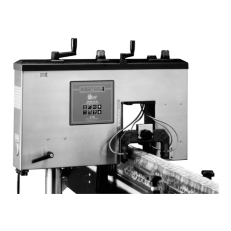
Filtec FT-100 User manual

FT-100/CI and FT-170/CI
Operation Guide
Document 40275-0913

Industrial Dynamics Company, Ltd.
Document 40275-0913 Copyright 2013. All rights reserved.
No part of this publication may be reproduced or used in any form or by any means (graphic,
electronic, or mechanical including photocopying, recording, taping, or information storage
and retrieval system) without written permission of Industrial Dynamics Company, Ltd.
filtecand Industrial Dynamicsare registered trademarks of Industrial Dynamics Company,
Ltd. All other trademarks are the property of their respective owners.
Contact Information
Corporate Headquarters 3100 Fujita Street,
Torrance, California
90505-4007
U.S.A.
Telephone:(310) 325-5633
FAX: (310) 530-1000
Internet: www.filtec.com
Mailing Address P.O. Box 2945,
Torrance, California
90509-2945
U.S.A.
Shipping Address 3100 Fujita Street,
Torrance, California
90505-4007
U.S.A.
Customer Service (800) 733-5173

Table of Contents iii
Document 40275-0913
Table of Contents
Preface. . . . . . . . . . . . . . . . . . . . . . . . . . . . . . . . . . . . . . . vii
Topics That This Guide Covers . . . . . . . . . . . . . . . . . . . . . . . . . . . . . . . . . vii
Audience of This Guide . . . . . . . . . . . . . . . . . . . . . . . . . . . . . . . . . . . . . vii
Conventions That Appear in This Guide. . . . . . . . . . . . . . . . . . . . . . . . . . . vii
1. Safety Information . . . . . . . . . . . . . . . . . . . . . . . . . . . . . . 1-1
1.1 Safety Notices and Safety Labels . . . . . . . . . . . . . . . . . . . . . . . . . . . . . . 1-2
1.2 X-Ray Radiation Safety Information . . . . . . . . . . . . . . . . . . . . . . . . . . . . 1-3
1.3 X-Ray Radiation Safety Labels on the FT-170/CI . . . . . . . . . . . . . . . . . . . . 1-6
1.4 Model FT-170/CI X-Ray Radiation Exposure Profiles . . . . . . . . . . . . . . . . . . 1-7
1.5 Certificate of X-Radiation Output. . . . . . . . . . . . . . . . . . . . . . . . . . . . . . 1-8
1.6 Gamma Radiation Safety Information . . . . . . . . . . . . . . . . . . . . . . . . . . . 1-9
1.7 Model FT-100/CI Radiation Exposure Profiles . . . . . . . . . . . . . . . . . . . . . .1-14
1.8 Determining the Model of Your Case Inspector . . . . . . . . . . . . . . . . . . . . .1-15
2. Components of the FT-100/CI and FT-170/CI . . . . . . . . . . . . 2-1
2.1 FT-100/CI and FT-170/CI. . . . . . . . . . . . . . . . . . . . . . . . . . . . . . . . . . . . 2-2
2.2 Components of the FT-100/CI and FT-170/CI . . . . . . . . . . . . . . . . . . . . . . 2-3
2.3 Optional Flap Inspectors. . . . . . . . . . . . . . . . . . . . . . . . . . . . . . . . . . . . 2-4
2.4 Control Panel . . . . . . . . . . . . . . . . . . . . . . . . . . . . . . . . . . . . . . . . . . . 2-6
2.5 Signal Beacon. . . . . . . . . . . . . . . . . . . . . . . . . . . . . . . . . . . . . . . . . . . 2-7
2.6 Reset Switch . . . . . . . . . . . . . . . . . . . . . . . . . . . . . . . . . . . . . . . . . . . 2-8
2.7 MASTER MENU . . . . . . . . . . . . . . . . . . . . . . . . . . . . . . . . . . . . . . . . . . 2-9
3. Operating the FT-100/CI and FT-170/CI . . . . . . . . . . . . . . . . 3-1
3.1 Overview of Operating the FT-100/CI and FT-170/CI . . . . . . . . . . . . . . . . . 3-2
3.2 Starting the FT-100/CI or FT-170/CI . . . . . . . . . . . . . . . . . . . . . . . . . . . . 3-3
3.3 Clearing the Current Counters. . . . . . . . . . . . . . . . . . . . . . . . . . . . . . . . 3-4

iv FT-100/CI and FT-170/CI Operation Guide
Document 40275-0913
3.4 Changing the Case Type . . . . . . . . . . . . . . . . . . . . . . . . . . . . . . . . . . . . 3-6
3.5 Selecting the Case Type . . . . . . . . . . . . . . . . . . . . . . . . . . . . . . . . . . . . 3-7
3.6 Adjusting the Height of the Inspection Beam . . . . . . . . . . . . . . . . . . . . . . 3-9
3.7 Adjusting the Guide Rails . . . . . . . . . . . . . . . . . . . . . . . . . . . . . . . . . . .3-10
3.8 Adjusting the Flap Inspectors . . . . . . . . . . . . . . . . . . . . . . . . . . . . . . . .3-11
3.9 Using the Reject History Counter . . . . . . . . . . . . . . . . . . . . . . . . . . . . . .3-16
4. Maintenance and Troubleshooting . . . . . . . . . . . . . . . . . . . 4-1
4.1 Maintenance Checklist . . . . . . . . . . . . . . . . . . . . . . . . . . . . . . . . . . . . . 4-2
4.2 Performing Daily Maintenance . . . . . . . . . . . . . . . . . . . . . . . . . . . . . . . . 4-3
4.3 Performing Weekly Maintenance . . . . . . . . . . . . . . . . . . . . . . . . . . . . . . 4-4
4.4 Verifying That the FT-100/CI Autoshutter Works Correctly . . . . . . . . . . . . . 4-6
4.5 Verifying That the FT-170/CI Auto Enable/Disable Monitor Works Correctly . . 4-7
4.6 Verifying That the FT-170/CI X-Ray On/Off Switch Works Correctly . . . . . . . 4-8
4.7 Troubleshooting . . . . . . . . . . . . . . . . . . . . . . . . . . . . . . . . . . . . . . . . . 4-9
4.8 Diagnostic Messages . . . . . . . . . . . . . . . . . . . . . . . . . . . . . . . . . . . . . .4-11
4.9 Case Types List. . . . . . . . . . . . . . . . . . . . . . . . . . . . . . . . . . . . . . . . . .4-15
Documentation Feedback . . . . . . . . . . . . . . . . . . . .Feedback-1
Help Us Improve . . . . . . . . . . . . . . . . . . . . . . . . . . . . . . . . . . . . Feedback-1
Ways to Submit Feedback . . . . . . . . . . . . . . . . . . . . . . . . . . . . . . Feedback-1
Documentation Feedback Form . . . . . . . . . . . . . . . . . . . . . . . . . . Feedback-2

List of Figures v
Document 40275-0913
List of Figures
Preface. . . . . . . . . . . . . . . . . . . . . . . . . . . . . . . . . . . . . . . vii
1. Safety Information . . . . . . . . . . . . . . . . . . . . . . . . . . . . . . 1-1
Figure 1-1. Safety Labels on the Model FT-170/CI Inspection System . . . . . . . . . 1-6
Figure 1-2. FT-170/CI Radiation Profile Schematic . . . . . . . . . . . . . . . . . . . . . 1-7
Figure 1-3. FT-170/CI Certificate of X-ray Output Measurement . . . . . . . . . . . . 1-8
Figure 1-4. Safety Labels on the FT-100/CI . . . . . . . . . . . . . . . . . . . . . . . . . .1-13
Figure 1-5. FT-100/CI Radiation Profile Schematic . . . . . . . . . . . . . . . . . . . . .1-14
2. Components of the FT-100/CI and FT-170/CI . . . . . . . . . . . . 2-1
Figure 2-1. Types of Cases That the FT-100/CI and FT-170/CI Can Inspect. . . . . . 2-2
Figure 2-2. Components of the FT-100/CI and FT-170/CI . . . . . . . . . . . . . . . . . 2-3
Figure 2-3. Flap Inspectors Mounted on the Inspection Head . . . . . . . . . . . . . . 2-4
Figure 2-4. Control Panel . . . . . . . . . . . . . . . . . . . . . . . . . . . . . . . . . . . . . 2-6
Figure 2-5. Reset Switch . . . . . . . . . . . . . . . . . . . . . . . . . . . . . . . . . . . . . . 2-8
Figure 2-6. MASTER MENU . . . . . . . . . . . . . . . . . . . . . . . . . . . . . . . . . . . . . 2-9
3. Operating the FT-100/CI and FT-170/CI . . . . . . . . . . . . . . . . 3-1
Figure 3-1. Locating the Main Power Switch . . . . . . . . . . . . . . . . . . . . . . . . . 3-3
Figure 3-2. CURRENT COUNTERS Menu . . . . . . . . . . . . . . . . . . . . . . . . . . . . . 3-5
Figure 3-3. CHANGE CASE TYPE Menu . . . . . . . . . . . . . . . . . . . . . . . . . . . . . . 3-8
Figure 3-4. Adjusting the Height of the Inspection Beam. . . . . . . . . . . . . . . . . 3-9
Figure 3-5. Adjusting the Guide Rails. . . . . . . . . . . . . . . . . . . . . . . . . . . . . .3-10
Figure 3-6. Adjusting the High Flap Sensor . . . . . . . . . . . . . . . . . . . . . . . . . .3-11
Figure 3-7. Adjusting the Side Flap Sensor . . . . . . . . . . . . . . . . . . . . . . . . . .3-12
Figure 3-8. Adjusting the Leading and Trailing Flap Sensor . . . . . . . . . . . . . . .3-13
Figure 3-9. Adjusting the Unslit Flap Sensor . . . . . . . . . . . . . . . . . . . . . . . . .3-14
Figure 3-10. Reject History Menu . . . . . . . . . . . . . . . . . . . . . . . . . . . . . . . . .3-16

vi FT-100/CI and FT-170/CI Operation Guide
Document 40275-0913
4. Maintenance and Troubleshooting . . . . . . . . . . . . . . . . . . . 4-1
Figure 4-1. Verifying the FT-100/CI Autoshutter. . . . . . . . . . . . . . . . . . . . . . . 4-6
Documentation Feedback . . . . . . . . . . . . . . . . . . . .Feedback-1

Preface vii
Document 40275-0913
Preface
Topics That This Guide Covers
FT-100/CI Operation Guide tells you how to use and maintain the
filtec FT-100/CI product.
Audience of This Guide
This guide is intended for use by operators who use the FT-100/CI
on a daily basis.
Conventions That Appear in This Guide
Use the following chart to learn about the typographic conven-
tions that appear in this guide.
This typeface or symbol... Indicates... Example...
abcd1234 A link to another document
or page in the current
document, which, when you
click on it, displays the other
document or the other page.
FT-100/CI and FT-170/CI Operation Guide
Important: Important information that
you might find helpful or
useful and best practice
suggestions.
Caution: That there is a potential for
damage to the equipment.
Depending on the particular
damage that can result, harm
to a person can also occur.
Important: Repeated laser fault
warnings might indicate that the
laser tube is failing and needs
replacement.
Caution: Stop the Lasetec III from
marking containers before you
load a backup PCF.
You must stop the Lasetec III to
load a new PCF.

viii FT-100/CI and FT-170/CI Operation Guide
Document 40275-0913
Warning: That there is a potential for
harm to an individual. As
harm can be mild or severe,
strictly observe the
information that is provided.
abcd1234 Emphasis, a definition of a
new concept, or a variable
for which you provide actual
text.
The system always displays the code editing
window with all menus and dialog boxes.
A text product code field is a set of
alphanumeric characters in a product code that
do not change.
+xor -x
abcd1234 Text, includingtitles, menus,
commands, and other
information that you see or
type on a screen.
This key toggles between Start Coding and Stop
Coding, depending on whether the Lasetec III is
idle or marking.
abcd1234 A best practice to follow, a
note, an example, a range of
values that you can type in a
field on a screen, and a
document to which to refer.
Best Practice:
Note:
Example:
Range:
See Also:
abcd1234 A file name or directory path. The system encrypts and internally stores the
encrypted password that you provide in the
Lasetec III configuration file lasetec.cfg.
This typeface or symbol... Indicates... Example...
Warning: To avoid serious injury,
check the focus LEDs only when
the laser is turned off.
Although the LEDs are low power,
they can still harm your eyes. Do
not look directly into the LEDs.

Safety Information 1-1
Document 40275-0913
1. Safety Information
The chapter explains the safety mechanisms filtec supplies with
your equipment and describes safe operating procedures when
using your filtec equipment.
This chapter also contains safety disclosure information,
including certifications required by the federal government and
other governing organizations and information voluntarily
provided by filtec.

1-2 FT-100/CI and FT-170/CI Operation Guide
Document 40275-0913
1.1 Safety Notices and Safety Labels
1.1.1 Introduction
To ensure your safety, filtec has included many safety notices
and labels within the product documentation and also attached
to the equipment. Always observe these safety instructions.
1.1.2 Safety Notices
This documentation includes two types of safety notices:
cautions, and warnings. Always observe the safety notices.
Cautions and warnings indicate safety issues.
1.1.3 Safety Labels
You encounter various safety labels within the equipment. These
labels are placed at strategic locations to help insure your safety.
Never remove safety labels from the equipment.
Warning: Indicates a potential for harm to a person. The harm
can be mild or severe; strictly observe the information
provided.
Caution: Indicates a potential for damage to the equipment.
Depending on the damage, a potential for harm to a person
might be created.

Safety Information 1-3
Document 40275-0913
1.2 X-Ray Radiation Safety Information
1.2.1 Introduction
The FT-170/CI uses X-rays. This section provides information
about radiation, radiation safety procedures, radiation certifica-
tions, and radiation characteristics of the FT-170/CI.
1.2.2 FT-170/CI Safety Mechanisms
The FT-170/CI contains three important safety mechanisms: the
warning light, the X-ray generator on/off switch (manual), and
the generator auto enable/disable feature.
Warning Light
The red warning light, located on top of the inspection head,
indicates the status of the X-ray generator. When the red light is
on, the inspection beam is enabled. When the red light is off, the
inspection beam is disabled.
Auto Enable/Disable Safety Feature
The Auto Enable/Disable feature is a circuit that:
• Turns the X-ray generator on to produce radiation thereby
producing the inspection beam,
• Turns the X-ray generator off to stop producing radiation
thereby stopping the inspection beam.
The auto enable/disable feature protects the operator automati-
cally by monitoring the production line. It automatically disables
the generator when the production line is stopped and it
automatically enables the generator when the production line is
started.
Warning: Never place a body part in the inspection tunnel while
the red light is on.

1-4 FT-100/CI and FT-170/CI Operation Guide
Document 40275-0913
X-Ray Generator On/Off Switch
The X-ray on/off switch is located on top of the inspection head
next to the warning light. This switch deactivates the X-ray
generator regardless of the auto enable/disable status.
1.2.3 How the FT-170/CI Provides Safety From X-Ray
Radiation
The filtec model FT-170/CI system utilizes an X-ray tube to
produce the X-ray radiation required for performing inspection
activities. The secured and insulated X-ray source housing
completely contains and shields all high voltage components
within the X-ray housing assembly.
The X-ray assembly contains a thermal safety sensor that
monitors the temperature of the X-ray housing assembly and
immediately shuts off (de-energizes) the X-ray generator when
the temperature exceeds 60 degree C. When the X-ray generator
is de-energized, no X-ray is produced and there is no residual
X-ray exposure.
The only possible way to be exposed to hazardous levels of
radiation using this equipment is externally, through excessive
exposure to a radiation source outside the body. There are no
by-products that can be ingested into the body.
The FT-170/CI is unlikely to create hazardous radiation levels for
the following reasons:
• The FT-170/CI’s X-ray generator produces a relatively weak
source of low energy (low penetrating power) X-ray radiation.
To receive a hazardous dose of radiation from this low energy
source would take extremely long exposure directly to the
main radiation beam.
• While we warn against placing hands or other body parts in
front of the X-ray beam when it is turned on, it would take
several hours of exposure for the hand to receive an excessive
radiation dose.
• The X-ray beam is tightly confined by shields and collimators
and is completely contained within the inspection tunnel.
Because the radiation beam does not spread outside the
inspection tunnel, it is highly unlikely that under normal
circumstances an appreciable radiation dose could be
received at a location other than directly in front of the
activated X-ray beam.

Safety Information 1-5
Document 40275-0913
1.2.4 X-Ray Safety Guidelines
Always follow these X-ray safety guidelines.
1. Do not tamper with the X-ray housing.
2. Do not place the hands between the X-ray source and the
detector when the X-ray is turned on.
3. The information on the labels that are affixed to the system
is very important. Always follow this safety information
explicitly.
4. If you have questions about safety or operation of the
FT-170/CI, contact filtec.
1.2.5 How filtec Measures X-Ray Radiation
This section tells you how filtec measures the gamma radiation
emitted by the FT-170/CI.
• All measurements are taken with Technical Associates Model
Pug-1 survey meter cross-calibrated against an air ionization
chamber survey meter whose response was corrected against
an Americium-241 test source.
• Disable - The radiation levels are not measurable.
• Enable - The extent of the main X-ray beam is completely
contained within the tunnel formed by the inspection head
and shielding bar. All radiation levels outside the main beam
are less than 0.05 mR/HR.
• The system has an optional safety input to disable the X-ray.
The normal inputs used are safety door interlock, or conveyor
run or any other safety item.
1.2.6 Restarting the X-Ray Generator
1. Turn the X-ray on/off switch on.
2. Start the production line if it is not currently running
Result: The red warning light turns on, the auto enable
activates the generator, and the generator begins emitting
the inspection beam.
The FT-170/CI is now ready to resume case inspection.

1-6 FT-100/CI and FT-170/CI Operation Guide
Document 40275-0913
1.3 X-Ray Radiation Safety Labels on the
FT-170/CI
1.3.1 Diagram
Use this diagram to determine the location of all safety labels on
the FT-170/CI.
Figure 1-1. Safety Labels on the Model FT-170/CI Inspection
System

Safety Information 1-7
Document 40275-0913
1.4 Model FT-170/CI X-Ray Radiation
Exposure Profiles
1.4.1 Diagram
Use this diagram to determine the radiation exposure profiles for
the FT-170/CI
Figure 1-2. FT-170/CI Radiation Profile Schematic
No. Description No. Description
1 Inspection head 5 Radiation detector
2 Inspection tunnel 6 5 cm isodistance contour
3 Sealed X-ray source 7 Shielding bar (1/4” steel plate)
4 Limits of main beam 8 Detector window
8
12
3
4
5
6
15
6
43
7
8 7
X-ray Gauge equals 45 KV @ 50 mA with 2 (.015 inch) BeCu Filters

1-8 FT-100/CI and FT-170/CI Operation Guide
Document 40275-0913
1.5 Certificate of X-Radiation Output
1.5.1 Diagram
Use this diagram to learn about the FT-170/CI Certificate of
X-Radiation Output.
Figure 1-3. FT-170/CI Certificate of X-ray Output
Measurement

Safety Information 1-9
Document 40275-0913
1.6 Gamma Radiation Safety Information
1.6.1 Introduction
This section provides information on radiation safety procedures,
radiation certifications, and the radiation characteristics of the
FT-100/CI.
1.6.2 FT-100/CI Safety Mechanisms
The FT-100/CI contains two important safety mechanisms: the
warning lights and the autoshutter.
Warning Lights
There are two warning lights located on top of the FT-100/CI
inspection head that indicate the position of the autoshutter.
• When the red light is on, the autoshutter is open. Do not
place a body part in the inspection tunnel while the red light
is on.
• When the green light is on, the autoshutter is closed. This
indicates a safe condition.
Either one of these lights, red or green, will always be on to
indicate the autoshutter status while the FT-100/CI is powered
up. If both lights are either on simultaneously or off simulta-
neously contact your service department immediately.
Autoshutter
The autoshutter protects the operator by automatically closing a
lead door in front of the gamma source when the production line
is stopped. When the production line begins moving again the
autoshutter automatically opens to allow the gamma source to
emit the inspection beam. The autoshutter lead door:
Warning: Never place a body part in the inspection tunnel while
the red light is on.

1-10 FT-100/CI and FT-170/CI Operation Guide
Document 40275-0913
• Opens to allow radiation to move from the gamma source
container thereby producing the inspection beam.
• Closes to seal the container and stop radiation moving from
the gamma source container thereby stopping the inspection
beam.
1.6.3 How the FT-100/CI Provides Safety From Gamma
Radiation
The filtec FT-100/CI utilizes a small quantity of the radioisotope
Americium-241 to produce low level gamma radiation. The
Americium-241 is in ceramic enamel form and its melting range is
in the region of 900 degrees to 1050 degrees centigrade.
The Americium-241 is sealed inside a special type 304 stainless
steel capsule that is double-fusion welded. This capsule is
mounted in a stainless steel enclosure inside the FT-100/CI
inspection head.
A radiation safety shutter, when opened, permits a narrow beam
of radiation to pass through the plastic radiation window in the
enclosure. When the safety shutter is closed all radiation is
contained within the source enclosure.
There are two possible ways to be exposed to hazardous levels of
radioactive material using this equipment: externally, through
excessive exposure to a radiation source outside the body, and
internally by ingesting radioactive material.
The FT-100/CI is unlikely to create hazardous radiation levels for
the following reasons:
• The FT-100/CI’s radiation source produces a relatively weak
source of low energy (low penetrating power) gamma
radiation. To receive a hazardous dose of radiation from this
low energy source would take extremely long exposure
directly to the main radiation beam.
• While we warn against placing hands or other body parts in
front of the gamma beam when it is turned on, it would take
several hours of exposure for the hand to receive an excessive
radiation dose.

Safety Information 1-11
Document 40275-0913
• The gamma beam is tightly confined by shields and colli-
mators and is completely contained within the inspection
tunnel. Because the radiation beam does not spread outside
the inspection tunnel, it is highly unlikely that under normal
circumstances an appreciable radiation dose could be
incurred at a location other than directly in front of the main
gamma beam when the safety shutter is opened.
• The radioactive material is sealed by double-fusion welds into
a stainless steel capsule. At manufacture, and again at instal-
lation, this capsule is subjected to rigorous tests capable of
detecting the leakage of five millionths of one percent of the
contents. Therefore as long as the source capsule’s integrity
is not compromised, radioactive material cannot be released.
• As an additional precaution, the regulatory agencies require
that a licensed individual inspect the radiation source and the
shutter mechanism and conduct a leak test at specified
intervals, that is, 36 months in the United States and 12
months in Canada (Industrial Dynamics personnel can do this).
1.6.4 Gamma Radiation Safety Guidelines
You have been supplied with a copy of the rules, regulations and
registration requirements for your location, however, the
following is a brief synopsis of the general requirements.
1. Understand the rules, regulations, and registration require-
ments regarding the use of this equipment at your location.
A copy of this is supplied with your FT-100/CI.
2. Do not open or tamper with the enclosure containing the
radioisotope source.
3. Do not place your hands, or any other body part, between
the source and detector when the safety shutter is open.
4. Have inspection and wipe tests performed by a licensed
technician at the specified intervals, that is, 36 months in
the United States and 12 months in Canada (Industrial
Dynamics personnel can do this).
Note: Keep a record of each inspection and test.
5. In the case of an accident which crushes or punctures the
source enclosure, seal off the area, cover the FT-100/CI and
surroundings with a plastic sheet or tarpaulin and call filtec
immediately.

1-12 FT-100/CI and FT-170/CI Operation Guide
Document 40275-0913
6. Do not relocate or dispose of the FT-100/CI without proper
approval. A licensed technician must perform this function.
7. If you have any questions, contact filtec.
1.6.5 How filtec Measures Gamma Radiation
This section tells you how filtec measures the gamma radiation
emitted by the FT-100/CI.
• All measurements are taken with Technical Associates Model
Pug-1 survey meter. The meter was cross calibrated against
an air ionization chamber survey meter whose response was
corrected against an Americium-241 test source.
• Autoshutter closed - The radiation levels are less than 0.05
mR/HR at distances greater than 5 cm from any surface of the
gauge (including inside the tunnel).
• Autoshutter open - The extent of the main gamma beam is
completely contained within the tunnel formed by the
inspection head and shielding bar. All radiation levels outside
the main beam are less than 0.05 mR/HR.
• The exposure rate in the main beam is measured to be
approximately 60 mR/HR at 5 cm from source enclosure
containing 300 millicuries.
This manual suits for next models
3
Table of contents
Other Filtec Security Sensor manuals

