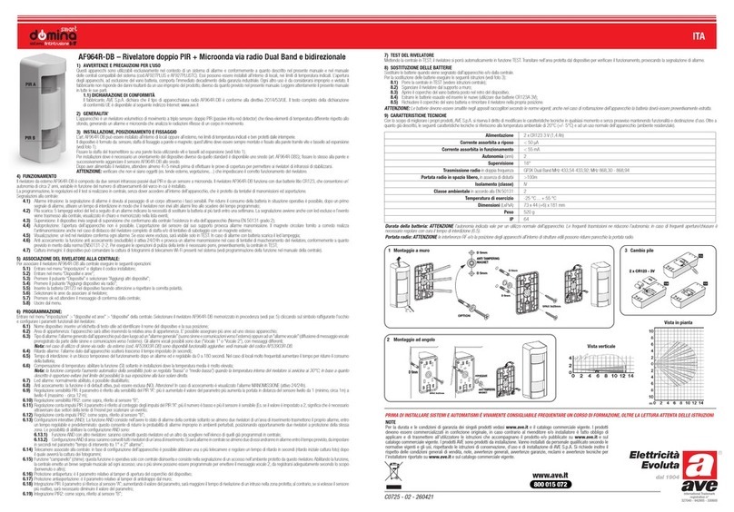
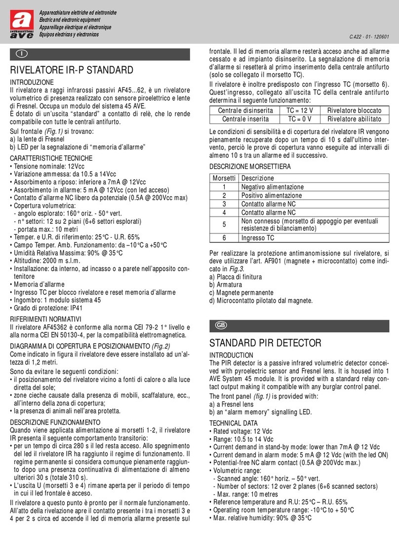
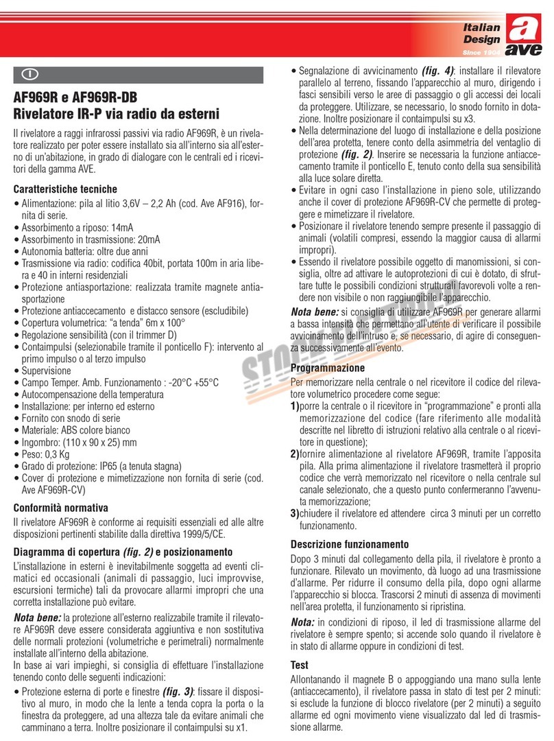
AVE AF970R User manual

AF970R
Barriera a raggi infrarossi via radio
AF970R Laserbeam è una barriera a raggi infrarossi per la prote-
zione di porte e finestre con trasmissione dell’allarme via radio che
dialoga con tutte le centrali della gamma radio AVE.
Come indicato in fig.1, è composta da due elementi (master e
slave) alloggiati in due profilati di materiale plastico, alimentati da
batterie al litio che generano tra loro una barriera di due raggi
infrarossi invisibili e modulati, interrompendo uno dei quali si ha
la trasmissione d’allarme via radio.
Caratteristiche tecniche
• Alimentazione: n.° 2 pile al litio 3,6V-2,2 Ah (cod. AVE AF916).
Fornite di serie
• assorbimento: 200µA per ogni barra
• autonomia: oltre 1 anno
• portata (distanza massima tra le barre): 5 m
• segnali trasmessi: allarme (interruzione raggio), fine allarme
(ripristino raggio), tamper, pila scarica, supervisione
• portata radio: 100m in campo libero e con totale assenza di
disturbi di fondo sulla banda
• tempo minimo di intervento 0,2 s
• grado di protezione: IP64
• peso: 0,7 Kg la coppia
• n.° 2 raggi di rilevazione.
Conformità normativa
La barriera AF970R è conforme ai requisiti essenziali ed alle altre
disposizioni pertinenti stabilite dalla direttiva 1999/5/CE.
Posizionamento (fig.1)
AF970R può essere installata a protezione di accessi sia in interni
che in esterni ed è la soluzione ideale per la protezione di porte,
finestre e varchi in genere, nel settore residenziale. Grazie all’ali-
mentazione tramite batteria al litio e alla trasmissione dell’allarme
via radio, non è necessario alcun cavo per l’installazione.
Nota bene: in esterni occorre evitare che la luce del sole possa
colpire direttamente uno dei ricevitori al fine di evitare una perdita
anche drastica della portata; si consiglia inoltre di aumentare, in
esterni, l’immunità alla luce solare diretta attraverso il dip-switch
n°3 (fig. 3).
Più barriere possono essere sovrapposte, attraverso il tappo di
giunzione fornito, al fine di ottenere più raggi.
Nota bene: nel caso di installazione di più barriere sovrapposte,
occorre predisporre i dip-switch n°1 e 2 in posizione diverse per
ciascuna barriera (cioè singola coppia Master e Slave), come indi-
cato in figura 5.
Predisposizione dip-switch (fig.3)
Il circuito master e quello slave di ciascuna barriera devono avere i
dip-switch impostati allo stesso modo.
Impostazioni dip-switch (fig.3):
1 e2= impostazione ritardo di trasmissione dell’allarme (espresso
in secondi)
3= regolazione funzionamento in interno o in esterno
4= abilitazione funzione fine allarme.
Nota bene: tutti i settaggi dei dip-switch vanno fatti prima di
inserire le pile.
Installazione e programmazione
Per installare ed memorizzare nella centrale o nel ricevitore il codi-
ce della barriera AF970R, procedere come segue:
1) sfilare i tappi ed estrarre con attenzione e delicatezza i circuiti
elettronici Master e Slave
2) impostare i dip-switch del Master e dello Slave secondo l’im-
piego previsto
3) porre la centrale o il ricevitore in “programmazione” e pronti
alla memorizzazione del codice (fare riferimento alle modalità
descritte nel libretto di istruzioni relativo alla centrale o al rice-
vitore in questione)
4) fornire alimentazione al circuito Master della barriera AF970R
tramite l’apposita pila (e quindi alimentare anche il circuito
Slave con l’altra pila fornita). Alla prima alimentazione il circui-
to Master trasmetterà il proprio codice che verrà memorizzato
nel ricevitore o nella centrale sul canale selezionato, che a
questo punto confermeranno l’avvenuta memorizzazione
5) abilitare il test di allineamento inserendo il ponticello TEST su
entrambi i circuiti della barriera (fig.2)
6) infilare i circuiti nelle barre ponendo attenzione al verso (evi-
denziato sulle etichette poste sul retro dei due profilati di mate-
riale plastico) e rimettere i tappi
7) posizionare le barre nel luogo di installazione, effettuando
delle prove funzionali: l’allineamento è automatico - l’interru-
zione di un raggio provoca un BEEP del buzzer interno alla
barra Master
8) identificata la posizione precisa delle barre, segnare i punti di
fissaggio a parete e la posizione del magnete del dispositivo
antimanomissione, se utilizzato (fig.1)
9) riaprire le barre, togliere i ponticelli TEST (fig.2), chiudere (se
necessario) il ponticello TAMPER e richiudere le barre con i
circuiti correttamente posizionati all’interno (al punto di tra-
smissione TX del Master deve corrispondere in linea d’aria il
punto di ricezione RX dello Slave, (fig.1)
10)fare i fori di fissaggio e quello del magnete di TAMPER (se
necessario) e procedere al fissaggio con tasselli.
Nota bene: se uno ostacolo interrompe un raggio per più di 30
secondi il sincronismo si ristabilisce dopo 1 minuto circa dalla
rimozione dell’ostacolo stesso.
Hi-Tech
Electric Solution
C447 1-09-2003 14:06 Pagina 2

Descrizione funzionamento
Correttamente installato, la barriera AF970R trasmette la condizio-
ne di allarme quando uno dei raggi viene interrotto.
Può inoltre trasmettere un segnale di “fine allarme” (dip-switch
n°4) quando il raggio si ripristina.
Nota: utilizzando AF970R con le centrali AVE via radio si ottiene
(attraverso la funzione di “fine allarme”) la segnalazione di “raggio
interrotto” equivalente alla segnalazione di “porta aperta”.
Incidenza della luce solare diretta
Occorre evitare o proteggere l’installazione qualora si possa verifi-
care la situazione illustrata in figura 4: la luce solare contiene una
notevole componente infrarossa che potrebbe saturare il ricevitore
provocando l’allarme; tale probabilità aumenta quanto maggiore è
la distanza fra le barre.
Le distanze massime sono le seguenti:
• In interni: 7m
• In esterni: 5m
Nota: la corretta posizione del dip-switch n°3 (fig.3) è fonda-
mentale al fine di migliorare il funzionamento in esterni.
Antiasportazione
AF970R è implicitamente autoprotetto poiché l’asportazione di una
delle due barre provoca comunque l’allarme. E’ comunque previsto
un dispositivo di protezione della barra Master, che si realizza
inserendo nella parete il magnete in dotazione (fig.1) in corri-
spondenza del relè Reed prima di sovrapporvi la barra.
Nota: nel caso in cui l’antiasportazione non venga utilizzata,
occorre tenere chiuso il ponticello TAMPER (fig.2).
Installazione di più barriere sovrapposte
Nella figura 5 viene illustrato un esempio di installazione di più
barriere in esterno e con l’antiasportazione inserita.
Verificare che:
1)per ciascuna barriera al punto di trasmissione TX del master
corrisponda in linea d’aria il punto di ricezione RX del corri-
spondente Slave (fig.2)
2)per ciascuna delle barriere sovrapposte i dip-switch n°1 e 2
siano predisposti in posizione diverse
3)il dip-switch n°3 sia impostato in ON (fig.3), per impostare
installazione in esterni
4)il dip-switch n°4 sia impostato in ON (fig.3), per abilitare il
“fine allarme”.
AF970R
Radio infrared barrier
AF970R Laserbeam is an infrared barrier for door and window pro-
tection equipped with radio-transmitted alarm. The device dialo-
gues with all AVE radio control panels.
As indicated in fig. 1, includes two elements (a master and a
slave) housed into two plastic section bars; these two elements are
powered by lithium batteries producing a barrier of two invisible
and modulated infrared rays. Whenever one of the two rays is
interrupted, the alarm is generated.
Technical data
• Power supply: 2 3.6V-2.2 Ah lithium batteries (code AVE
AF916), supplied with the kit
• electrical input: 200 µA for each bar
• range of operation: over 1 year
• range (maximum distance between the bars): 5 m
• transmitted signals: alarm (ray interruption), end of alarm (ray
restoration), tamper, exhausted battery, supervisory function
• radio range: 100 m in free air and noise-free band
• minimum operating time: 0,2 seconds
• protection degree: IP64
• weight: 0.7 Kg the two elements
• 2 detection rays.
Standard compliance
The barrier AF970R is in compliance with the essential require-
ments and other relevant provision of directive 1999/5/CE.
Positioning (fig.1)
AF970R can be installed for indoor and outdoor access protection
and is the most suitable solution for door, window and passage
protection in the domestic environment. Thanks to the lithium bat-
tery power supply and the alarm transmitted by radio, no cable is
required.
Note: If the device is installed outdoors, avoid direct sunlight on
the receivers to prevent range losses. Furthermore, we suggest
increasing protection against direct sun by means of dip-switch 3
(fig. 3) in the case of outdoor installation.
To obtain several rays, several barriers can be superposed by
means of the junction plug supplied by the manufacturer.
Note: in the case of installation of several superposed barriers, the
dip-switch 1 and 2 position will be different for each barrier (that
is, each single Master and Slave couple) as indicated in fig. 5.
Dip-switch setup (fig.3)
The dip-switches of the master and slave circuits of each barrier
must be set in the same way.
C447 1-09-2003 14:06 Pagina 3

Dip-switch setup (fig. 3)
1and 2= alarm transmission delay (in seconds)
3= operation setup for internal or external installation
4= alarm stop enabled.
Note: all dip-switches must be set up before inserting the battery.
Installation and programming
To install and store the AF970R barrier code onto the control panel
or the receiver, do as follows:
1) remove the plugs and also the Master and Slave electronic cir-
cuits with great care
2) set up the Master and the Slave dip-switches according to the
intended use
3) prepare the control panel or the receiver for “programming”
and for storing the code (refer to the instructions of the User’s
manual relating to the control panel or the receiver)
4) energize the Master circuit of the AF970R barrier using the
corresponding battery (and also energize the other Slave cir-
cuit by using the second battery supplied by the manufactu-
rer). When energized for the first time, the Master circuit tran-
smits its code to the receiver or the control panel for storing
onto the selected channel. Storing is then confirmed
5) enable the alignment test by inserting the TEST jumper on both
barrier circuits (fig.2)
6) insert the circuits in the bars following the right direction
(which is shown on the labels on the back of the two plastic
section bars) and put the plugs back to their seat
7) position the bars where they must be installed and make some
operating tests: alignment is automatic – a BEEP by the buzzer
housed inside the Master bar indicates ray interruption
8) once the correct bar position has been located, mark the wall
fixing points as well as the tamper device magnet position, if
any (fig.1)
9) re-open the bars, remove the TEST jumpers (fig. 2) , close the
TAMPER jumper (if necessary) and close the bars after positio-
ning the circuits at their place (the TX Master transmission
point must correspond to RX Slave reception point in a bee-
line (fig.1)
10)make the fixing holes and the hole for the TAMPER magnet (if
necessary) and then fix the unit by means of the dowels.
Note: if a hindrance causes ray interruption for more than 30
seconds, synchronism will be reset after 1 minute from hindrance
removal.
Operation description
If properly installed, the AF970R barrier transmits an alarm when
one of the rays is interrupted.
It can also send a signal of “end of alarm” (dip-switch no. 4) when
the ray is restored.
Note: when AF970R is used with AVE radio control panels (throu-
gh the “end of alarm” function), the signal of “ray interruption”
corresponds to the signal “open door”.
Direct sunlight effects
The plant must be protected against the effects shown in figure 4:
in fact, due to its infrared rays, sunlight could cause the alarm by
saturating the receiver. This risk increases as greatest the distance
between the two bars.
The maximum distances are the following:
• for indoor installation: 7 meters
• for outdoor installation: 5 meters.
Note: the dip-switch n° 3 (fig. 3) must be put in the correct posi-
tion in order to ensure correct operation when the device is instal-
led outdoors.
Tamper device
AF970R is self-protected as bar removal causes the alarm tran-
smission. Anyway, a device for the Master bar protection has been
provided: it consists of a magnet to be inserted into the wall (fig.
1) close to the Reed relay before installing the bar.
Note: if the tamper device is not used, the TAMPER jumper must
be kept closed (fig.2).
How to install several superposed barriers
Figure 5 shows an example of how to install several barriers out-
doors provided with a tamper device.
First make sure that:
1)for each barrier, the TX Master transmission point corresponds
to the Slave RX reception point in a bee-line (fig.2)
2)for each superposed barrier, dip-switches no. 1 and 2 must be
located in different positions
3)dip-switch no. 3 must be ON (fig.3) for outdoors installation
programming
4)dip-switch no. 4 must be ON (fig.3) for “end of alarm” pro-
gramming.
C447 1-09-2003 14:06 Pagina 4

RX
RX
AVVERTENZE I prodotti devono essere commercializzati in confezione originale, in caso contra-
rio al rivenditore e/o installatore è fatto obbligo di applicare e di trasmettere all'utilizzatore le istru-
zioni d'uso che accompagnano il prodotto. Dopo aver aperto l'imballaggio, assicurarsi dell'integrità
dell'apparecchio, nel dubbio non utilizzare l'apparecchio e rivolgersi a personale professionalmente
qualificato. L'apparecchio, anche se imballato, deve essere maneggiato con cura e immagazzinato in
luogo asciutto ad una temperatura compresa tra –5…+40°C.
Si ricorda inoltre:
•Il prodotto, se non diversamente specificato, è destinato all'utilizzo in luoghi asciutti e non polve-
rosi. Per ambienti particolari utilizzare prodotti specifici.
•Nel caso di prodotti alimentati con batterie quando queste sono scariche vanno sostituite con un
modello equivalente e smaltite secondo le vigenti norme. Nel caso dovesse verificarsi fuoriuscita
del liquido, sostituirle immediatamente, pulire accuratamente l’alloggio delle batterie, proteggendo-
si le mani con guanti al silicone. In caso di contatto con il liquido lavarsi accuratamente le mani.
• Nel caso di prodotti utilizzanti batterie al Litio, unitamente a quanto sopra, tenere conto che queste
presentano pericolo d’esplosione; devono quindi essere sostituite da personale specializzato.
DIRECTIONS The products must be sold in their original packing. Where this is not the case, the
retailer and/or the installer must apply and transmit the instructions for use supplied with the pro-
duct to the user. After opening the packing, check the product’s ntegrity; in case of doubt, do not use
the equipment and consult skilled personnel. Even when wrapped in its packing, the equipment must
be handled with care and stored in a dry room at a temperature between –5 and +40°C.
Remember:
• If not otherwise indicated, the product must be used in dry rooms free of dust.
Use specific products for special environments.
•In the case of products powered by batteries, should they be discharged, they must be replaced
with similar batteries and disposed according to the rules in force. In the case of liquid leaks,
replace them immediately, clean the battery housing with care wearing silicone gloves. In the case
of liquid contact, wash your hands carefully.
•In the case of products powered with lithium batteries, in addition to the above precautions,
remember that they must be replaced by skilled personnel as they present explosion hazard.
C.447 - 00 - 221102
Tamper
55 mm RX1
Master
TX1
Slave
5 m
Inserire sulle viti
di fissaggio i
distanziali forniti
TX2
RX2
333 mm
22 mm
24 mm
inserire sulle viti di fissaggio
i distanziali forniti.
Mount the spacers provided by
the manufacturer onto the fixing
screws
Fig. 1
Fig. 3
Fig. 2 a) posizione della pila
b) relè magnetico (Reed) per antiasportazione
c) ponticello abilitazione protezione tamper
d) dip-switch di programmazione
e) ponticello esclusione test
f) trasmettitore (TX)
g) ricevitore (RX)
a) battery location
b) tamper magnet relay (Reed)
c) tamper protection activating jumper
d) programming dip-switch
e) test disabling jumper
f) transmitter (TX)
g) receiver (RX)
-
+
-
+af
d
e
OFF
OFF
ON
ON
c
b
g
1
2
3
4
OFF ON
interno
0” 1
21”
OFF ON 1
22”
OFF ON
3
4esterno
fine allarme
1
23”
OFF ON
Fig. 4
RX1A
MASTER
TX1A
RX2A
TX2A
RX3A
TX3A
TX1B
SLAVE
RX1B
TX2B
RX2B
TX3B
RX3B
1
2
OFF ON
3
4
1
2
OFF ON
3
4
1
2
OFF ON
3
4
1
2
OFF ON
3
4
1
2
OFF ON
3
4
1
2
OFF ON
3
4
Fig. 5
indoors outdoors
end of alarm
C447 1-09-2003 14:06 Pagina 1
Other AVE Security Sensor manuals

AVE
AVE AF974R-DB User manual

AVE
AVE Domina Smart AF964R-DB User manual

AVE
AVE AF975R-DB User manual

AVE
AVE LUCE AMICA User manual

AVE
AVE LUCE AMICA 44 068/3F Series User manual

AVE
AVE AF974R-DB User manual

AVE
AVE AF45 62 Series User manual

AVE
AVE AF969R User manual

AVE
AVE domina AF976R-DB User manual

AVE
AVE AF962 User manual
Popular Security Sensor manuals by other brands

S+S Regeltechnik
S+S Regeltechnik AERASGARD RLQ-CO2-W Operating Instructions, Mounting & Installation

IMI SENSORS
IMI SENSORS 682B05 operating guide

Haneco
Haneco SKYLUX Smart Control installation guide

System Sensor
System Sensor EBR Installation and maintenance instructions

Leica
Leica Ultra user manual

Panasonic
Panasonic SF4B-F31G(V2) instruction manual