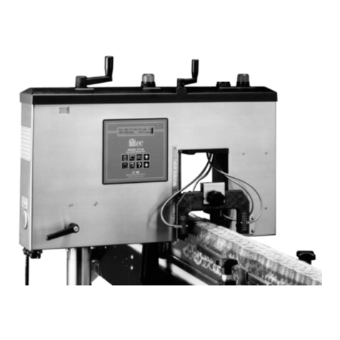
Filtec FT-50 Assembly instructions

Cross Beam
Label Detectors
Installation and Setup Guide for
Models FT-50 and FT-70
3003-0395

Cross Beam Label Detectors
Installation and Setup Guide for Models:
• FT-50
• FT-70
Document 3003-0395

Industrial Dynamics Company, Ltd.
Document 3003-0395 Copyright. All rights reserved.
No part of this publication may be reproduced or used in any form or by any means (graphic,
electronic, or mechanical including photocopying, recording, taping, or information storage
and retrieval system) without written permission of Industrial Dynamics Company, Ltd.
Filtecand Industrial Dynamicsare registered trademarks of Industrial Dynamics Company,
Ltd. All other trademarks are the property of their respective owners.
Contact Information
Corporate Headquarters: 3100 Fujita Street,
Torrance, California
90505-4007
U.S.A.
Telephone:(310) 325-5633
FAX: (310) 530-1000
Internet: www.filtec.com
Mailing Address: P.O. Box 2945,
Torrance, California
90509-2945
U.S.A.
Shipping Address: 3100 Fujita Street,
Torrance, California
90505-4007
U.S.A.
Customer Service: (800) 733-5173

Contents
System Descriptions
................................................
1
Bottle Specifications
................................................
4
Function Descriptions
...............................................
4
InstallationRequirementsand Instructions
..............................
7
SensorMechanical Alignment
........................................
9
SensorCalibration
.................................................
10
FT
-
50 Trigger to Label Detector Center Point Distance
(Label Detector
P/N
22353
only)
......................................
11
Fine Adjustment of Distance (Trigger to Label)
..........................
13
Adjustment of Sensor Look Distance (Label)
...........................
15
Maintenance. Troubleshooting. and Replacement
........................
16
Sensor Assembly Replacement
......................................
19
Drawings and Parts Lists
...........................................
22
Industrial
Dynamics
Company.
Ltd.
Document3003-0395

Industrial
Dynamics
Company,
Ltd. Document 3003-0395

CROSS
BEAM LABEL DETECTORS
P/N
22353
P/N
32769
Kit,
Label Inspection,
Cross
Beam
Kit,
X
-
Beam, Head Mounted
System
Descriptions
The Cross Beam Label Detector, P/N 22353, (Figure
1),
and the
Head
-
Mounted Cross Beam Label Detector, P/N 32769, (Figure
2),
are optional accessories for the FT
-
50 system. The Cross
Beam Label Detector is mounted on the Kit, Mounting Bracket,
Inspection Station,
P/N
22344. The Head Mounted Cross Beam
Label Detector is mounted on blocks bolted to the FT
-
50's
bottom. Both Label Detectors are operated by the FT
-
50. Both
Label Detectors check bottles that are transparent
to
infrared
radiation for the presence of body labels.
Each Label Detector uses two infrared photoelectric transmitters
and
two
infrared receivers, placed diagonally
at
45°
to
the flow
of bottles on the conveyor. Each transmitter transmits across the
Production Conveyor to its receiver. When
a
liquid
-
filled
transparent unlabeled bottle passes between
a
transmitter and its
receiver, the transmitter's light beam refracts away from the
receiver, except during
a
brief interval when the beam
is
passing
straight through the bottle's centerline.
If
the bottle
has
a
body
label, no infrared light reaches the receiver during this
centerline
interval. Each transmitter
-
receiver
pair
is connected
to
a
Photo Amplifier
(P/N 19140).
Both Label Detectors each
have two Photo Amplifiers; they are located either in the
Inspection Station Electronic Enclosure (Label Detector P/N
22353) or in the
FT
-
50
(Label Detector P/N 32769).
In
the Label
Detector
P/N
22353, the outputs from both Photo Amplifiers are
combined (logically OR’ed) onto
a
single FT
-
50 Sensor input
line. In the Label Detector P/N 32769, each Photo Amplifier
output is connected to
a
separate FT
-
50 Sensor input line. The
FT
-
50 compares the logic state of the Sensor input line (Label
Detector P/N 22353) or the logic state of each of the two Sensor
input lines (Label Detector P/N 32769) to an internal table to
determine if the bottle should be accepted
or
rejected.
Power
(+20 VDC)
and a Ground reference are supplied by the
FT
-
50 Main Terminal Block
TB1,
through the cable connecting
the FT
-
50
to
the Inspection Station JunctionBox.
Both Label Detectors require that
a
High Resolution Encoder
(Assembly
P/N
24997, Installation
Kit
P/N
24444), driven by the
Production Conveyor, be connected
to
the FT
-
50. The High
Resolution Encoder is installed per Installation Drawing I-00425.
The Encoder enables the FT
-
50 to precisely track when each
bottle's centerline is passing through the cross beam measure
-
Industrial Dynamics Company
Ltd. Document 3003-0395
I

ment point.
This
enables the
FT
-
50
to accept only those bottles
with
body labels, instead
of
unlabeled bottles (which would
appear
to
have body labels by being measured early
or late).
Top View
2
Figure
1.
Cross
Beam Label Detector,
P/N
22353
Industrial
Dynamics
Company,
Ltd. Document 3003-0395
Side View

Isometric
View
Figure
2.
Head
-
Mounted X
-
Beam Label
Detector
P/N
32769
Industrial
Dynamics
Company
Ltd. Document 3003-0395
3

Bottle Specifications
Maximum Bottle Diameter:3.25 inch
(85.0
mm)
Minimum Bottle Spacing:1.00 inch
(25.4
mm)
NOTE
A
minimum
1
inch bottle spacing
on
the Production Conveyor
is
required.
Failure to maintain this spacing may result in
bottles being falsely accepted or rejected.
Function Descriptions
The
FT
-
50
software contains specific functions that define the
inspection parameters for the Label Detector Sensors and
Display, and reset the contents of the Reject Counters. These
functions are:
BOTTLE FINISH
Function Key: MISSING BODY STATUS
TRIGGER TO LABEL (Label Detector
P/N
LOOK DIST LABEL
ADJUST DIST LABEL
22353
only)
COUNTERS
Function Key: TOTAL MISSING BODY
RESET MISSING BODY
LBL
These functions can be either Status functions (displaying output
to the operator), Command functions (accepting input from the
operator, or Status/Command functions (displaying output and
accepting input).
MISSING
BODY
STATUS
-
(STATUS/COMMAND)
Toggles inspection for body labels ON or
OFF.
Enables the
function to be turned ON or OFF
in
both the OPERATE and the
CALIBRATE modes.
(Range: ON or OFF, Default: OFF)
4
Industrial Dynamics Company, Ltd. Document 3003-0395

TRIGGER TO LABEL
-
(STATUS/COMMAND)
The distance, in millimeters, between the center point of the
Inspection Trigger Beam and the center point of the Label
Detector. This distance is used by the processor to establish the
proper timing for label inspection.
For Label Detector P/N 22353, the Default distance is 150
mm,
and
a
user message to enter the measured distance
appears on
the Display.
For Label Detector P/N 32769, the Default distance is 102
mm,
and
a
user message does
not
appear on the Display.
LOOK DlST LABEL
-
(STATUS/COMMAND)
Adjusts the distance, in millimeters, during which the label
sensor output will be evaluated by the processor. This
gate
is
centered
on
the center point of the Label Detector.
(Range: 1
-
25
mm,
Default 12 mm)
ADJUST DlST LABEL
-
(STATUS/COMMAND)
For Label Detector 22353, adjusts the distance set in TRIGGER
TO LABEL, using the
FT
-
50
Display as
a
monitor.
For Label Detector P/N 32769, enables adjustment of the 102
mm default Trigger
to
Label distance.
This function is used in Calibrate Mode. Refer
to
Sensor
Mechanical Alignment
(page 9), and
Sensor Calibration
(page
10).
TOTAL MISSING BODY
-
(STATUS)
Displays the total number
of
containers that failed inspection for
the Body Labels since the last time the counter was reset.
(Range:
0
-
99,999,999)
RESET MISSING BODY
-
(COMMAND)
When selected and executed by pressing either
UP
or
DOWN
arrow key, resets the
TOTAL
MISSING
BODY
Reject counter.
If
the previous count value
is
to
be saved,
it
must be recorded
externally; there is
no
storage for the counter value once
it
is
reset.
Industrial
Dynamics
Company
Ltd. Document 3003-0395
5

LAST REJECT DETECTED
-
(STATUS)
Displays the cause for the last reject.
If
caused by
a
missing
label, the bottom line of the Liquid Crystal Display
shows MISSING BODY. Following either
of
these
messages, there will be up
to
six
numbers (example: MISSING
BODY
-
4,5,6,
1),
corresponding to the number or numbers for
the Sensors which saw
a
label.
ALARM MISSING BODY LBL
-
(STATUS/COMMAND)
Sets the number of consecutive MISSING BODY rejects that
cause an alarm condition. Rejects must be consecutive. Each
good
container that passes through the
FT
-
50
will reset the
Alarm Counter to zero.
(Range:
OFF,
1
-
250,
Default:
OFF)
6
Industrial Dynamics Company,
Ltd. Document 3003-0395

Installation Requirements and Instructions
The X
-
Beam Label Detector
P/N
32769 is already installed as an
integral
part
of the FT
-
50. User installation is not required.
Perform the following steps to install Label Detector
P/N
22353:
1.
Double
-
check the indents of the upstream positioning Guide
Rails.
Measure,
and adjust both Guide Rail indents as
required to
ensure
that
the upstream Guide Rails position
the Production Bottles
exactly
on
the FT
-
50 and Inspection
Station
(P/N
22353
only)
centerline, as shown in Installation
Drawing
1
-
00412.
NOTE
This Guide Rail measurement is
critical
for
proper Label
Detector operation.
Ensure
that the Guide Rails are positioned
correctly.
If,
due to Guide Rail positioning error, the bottles
flow
on
one side
of
the
FT
-
50
and Inspection Station
centerline,
the
Label Detector
P/N
32769
cannot
be adjusted
to operate correctly, and the Inspection Station Vertical Tubes
supporting Label Detector
P/N
22353
must be offset
to
compensate
for
the
error.
CAUTION
Shut down and lock out drive power
to
the Production
Conveyor and Takeaway Conveyor
2. Install the Inspection Station and the wiring from the
Inspection Station‘s JunctionBox to the FT
-
50 per Installation
Drawing 1
-
00399.
Industrial
Dynamics
Company
Ltd. Document 3003-0395
7

NOTE
For best results, the Label Detector centerline should be at
least
18
in. downstream from the outside edge
of
the FT
-
50.
This allows approximately
13
in. working space between
the
FT
-
50 and the Label Detector, should the FT
-
50 require service.
Similarly, the Label Detector centerline should
be
at least
10
in. upstream from the Proline rejector's centerline, to ensure
that bottles have approximately
3
in. clearance from the Label
Detector's outermost edge when they are rejected.
The correct position of the Inspection Station Horizontal and
Vertical Tubes relative
to
the centerlines
of
the Production
Conveyor and bottles, as shown in Installation Drawing
I
-
00399,
is
critical
in determining inspection accuracy. When
installing the Inspection Station:
The Production Bottle's center must be placed exactly
on
the Production Conveyor Centerline, and
The Inspection Station must be installed
so
that the
Centering
Tool's
point
(0,0
point
on
the Horizontal Tube's
scales) is suspended directly over the center of the
Production Bottle's
cap.
2.
Using the Production Bottle on the Production Conveyor's
centerline as
a
reference aid, install the Label Detector
Assembly on the Inspection Station. Position the Label
Detector Assembly approximately
1
in.
(25
-
30
mm) above
the labels to be inspected.
8
Industrial
Dynamics
Company,
Ltd. Document 3003-0395

Sensor Mechanical Alignment
CAUTION
Shut
down and
lock
out
drive power
to
the
Production
Conveyor
and
Takeaway Conveyor prior
to
servicing
Prerequisites from FT-50 Manual
For both Label Detectors
(P/N
22353 and
P/N
32769), ensure
that:
1.
The FT
-
50 Trigger, High Resolution Encoder and Rejector are
set
up
and calibrated per the FT
-
50 Manual, Chapter
2.
2.
The FT
-
50 Container Parameter Table and System Parameter
Settings Table contain the most recent values for the bottle
type to be inspected in the User Defaults and System
Settings memory, per the FT
-
50 Manual, Chapter
2.
Label Detector
P/N
32769 does not require mechanical
alignment.
Perform mechanical alignment of Label Detector
P/N
22353 per
Drawing 22353, Item
7.
Industrial
Dynamics
Company
Ltd. Document 3003-0395
9

Sensor Calibration
CAUTlON
Shut down and lock
out
drive power
to
the Production
Conveyor and Takeaway Conveyor before proceeding.
Perform the following procedures
to
calibrate Label Detector
P/N 22353 and Label Detector P/N 32769. A fully filled
unlabeled Production Bottle is required.
1.
Ensure
that
no bottles are between the Label Detector
Sensors.
2.
a.
For Label Detector P/N 22353, open the Inspection
Station JunctionBox.
b. For Label Detector P/N 32769, remove the
FT
-
50
cover.
3.
Set
each
of
the
two
Amplifier Gain potentiometers fully
counterclockwise (minimum Gain).
4.
Adjust each Amplifier's potentiometer the same amount
clockwise until each LED flashes steadily.
5.
Place the filled unlabeled Test Bottle exactly on the FT
-
50
and Inspection Station (P/N 22353 only) centerline.
6.
Verify that both LEDs flash
at
the same time and
at
the same
rate.
If
not:
a.
For Label Detector
P/N
22353
1.
Verify that the FT
-
50, the Inspection Station, and the
Test Bottle are
all
on the Production Conveyor
centerline.
2. Verify
that
the Label Detector is symmetrically
positioned about the centerline.
3.
Perform
steps
5. and 6. again.
If
the
LEDs
still
do
not
blink
at
the same rate, contact
IDC
Customer Service.
b.
For
Label Detector P/N 32769, contact
IDC
Customer
Service.
10
Industrial
Dynamics
Company,
Ltd. Document 3003-0395

7.
a.
For Label Detector P/N 22353, close the Inspection
Station JunctionBox.
b.
For
Label Detector P/N
32769,
install the FT
-
50 cover.
FT
-
50 Trigger to Label Detector Center Point Distance
(Label Detector P/N 22353 only)
Activate Label Logic
Perform the following procedures for Label Detector P/N 22353
only:
NOTE
The Production and Takeaway Conveyors
are
still shut
down and locked out.
If other Label Detectors
on
the Inspection Station
Mounting Bracket Kit require alignment and calibration
(example: Crossbeam Label Detector), perform their set
-
up
before proceeding.
1.
Press the BOTTLE FINISH function key repeatedly until
the Display's
top
line shows MISSING BODY STATUS.
2. Press the UP
or DOWN arrow keys
as
required until the
Display's bottom line shows ON.
The Radioisotope Source Manual Shutter Rod MUST be
pushed into the FT
-
50
(NO
Red Paint Shows) BEFORE
Inserting Hands
Into
Inspection Tunnel. Failure
to
Comply
Will Result in Radiation Exposure.
NOTE
If the
Label Detector
P/N
22353
is
the
first
Label Detector
to
be set up
on
this Inspection Station, then perform this
procedure.
If
not,
go
to
Fine Adjustment
of
Distance
(Trigger
to
Label)
(page
13).
The distance from the FT
-
50 Trigger to the Label Detector
center point is the initial approximation
of
the Trigger to
Label Distance.
Industrial
Dynamics
Company
Ltd. Document 3003-0395
11
CAUTION

1.
Measure the distance in millimeters from the FT
-
50 Trigger
Beam to the Centering
Tool's
point (Label Detector center
point); note the value.
2.
Press the BOTTLE FINISH function key until the Display's
top line shows INSP TRIG TO LABEL.
3.
Press the
UP
or
DOWN arrow keys as necessary until the
Display's bottom line shows the distance from the FT
-
50
Inspection Trigger Beam to the Label Detector center point in
millimeters.
4.
When measurement
is
complete, pull out the Radioisotope
Source Manual Shutter
Rod.
12
Industrial
Dynamics
Company,
Ltd. Document 3003-0395

Fine Adjustment
of
Distance (Trigger to Label)
For both Label Detector models, perform the following
procedure:
1.
Remove the Production and the Takeaway Conveyor lock
-
outs and energize the Conveyors. Allow Production Bottles
to flow past the FT
-
50 and the Inspection Station.
2.
Press the
BOTTLE
FINISH function key until the Display
shows ADJUSTDISTNCE LABEL. The bottom line shows
EXECUTE.
3.
Press the
UP
or DOWN arrow keys as necessary until the
Display shows:
NOTE
The first
two
messages are displayed for approximately
four
seconds each.
"
Run
only
'one' container
at
a
time
"
means
run
only one
type
of
container
at
a
time.
Normal
Production Bottles are acceptable for this procedure.
The last message
is
a
prompt which waits
for
the Sensor
number
(1
or
2)
to be entered.
For Label Detector
22353,
enter
1.
For Label Detector
32769,
enter
1
or
2.
4.
Press the
UP
or
DOWN
arrow keys until the Display's
bottom
line shows
1.
Industrial
Dynamics
Company
Ltd. Document 3003-0395
13

5.
The Display changes to:
6.
Observe the Display for one
of
the following four possible
patterns:
a. The Distance (Trigger to Label) is correct:
(Ideal display
-
no
pattern)
(Acceptable display
-
small pattern around center)
b. The Distance (Trigger
to
Label)
is
too short:
c. The Distance (Trigger to Label)
is
too
long:
7.
Determine
if
the Distance (Trigger to Label) is set correctly
and
adjust as necessary:
a.
Observe the Display as bottles pass through the Label
Detector. Note the bottles' pattern on the display.
b.
If
the bottles' pattern is centered, the Distance (Trigger
to
Label)
is
correct.
c.
If
the bottles' pattern
is
located
to
the left, press the
UP
arrow key to
center the pattern.
d.
If
the bottles' pattern
is
located
to
the right, press the
DOWN arrow key to center the pattern.
NOTE
When
the
average distance
is
changed using the
UP
or
DOWN
Arrowkeys, the Display's bottom line will change to
"
LABEL
DIST
=
nnn
MM
"
,
where
"
nnn
"
is the current changed
value, and
"
MM
"
is
the unit (millimeters).
14
Industrial
Dynamics
Company.
Ltd. Document 3003-0395

8.
Press the DIAGNOSTICS key to
exit
the ADJUST
DISTNCE LABEL function. The Display shows:
9.
a.
For
Label Detector P/N 22353, go to
Adjustment
of
Sensor
Look
Distance (Label)
below.
b.
For
Label Detector P/N 32769, return to Step
1.
to test
and adjust Sensor
2.
Adjustment
of
Sensor
Look
Distance (Label)
For
both model Label Detectors, perform the following
procedure with the Production Conveyor moving, but with
no
bottles passing through the Label Detector:
1.
Press the BOTTLE FINISH function key
until
the Display
shows LOOK DIST LABEL,
or
the particular
text
assigned
to
this
FT
-
50.
2. Press the
UP
or
DOWN arrow keys until the Display's
bottom line shows
12.
3.
Insert one
good
(labelled) Production Bottle and one
missing (Body) label
Production Bottle onto the Production
Conveyor upstream
of
the bottle positioning guide rails.
If
the good bottle is accepted and the missing label bottle
is
rejected, the Look Distance function
is
correct.
If
not, adjust
the FT
-
50
a.
For Production Bottles
of
less than
50
mm
diameter,
press the
UP
or
DOWN arrow keys
to
decrease the
value shown on the Display's bottom line by
1
(mm).
b. For Production Bottles greater than 50 mm Diameter,
press the
UP
or
DOWN arrow keys to increase the
value shown on the Display's bottom line by
1
(mm).
4.
Repeat step 3.
until
the good bottle
is
accepted and the
missing label bottle
is
rejected.
If
the value
of
the
Look
Distance (Label) function decreased
to
1
mm
or increased to
25
mm,
contact the Industrial Dynamics' Customer Service
Department.
Industrial
Dynamics
Company
Ltd. Document 3003-0395
15
Other manuals for FT-50
3
This manual suits for next models
1
Table of contents
Other Filtec Security Sensor manuals
Popular Security Sensor manuals by other brands
LUXOMAT
LUXOMAT PD4-M-DALI/DSI-1C-FC Installation and operating instruction
Magnum Innovations
Magnum Innovations M EOSW Series manual

SSS Siedle
SSS Siedle BMM 611-0 Product information
Satel
Satel AQUA manual
Honeywell
Honeywell Satronic IRD 1010 manual
Bircher Reglomat
Bircher Reglomat Jupiter operating instructions
System Sensor
System Sensor InnovAir DH100ACDCI Installation and maintenance instructions
Rotech
Rotech FJC-DL001 user manual
Bosch
Bosch ISN-AP1-T installation guide
Dalsa
Dalsa Rad-icon 1520 user manual

HD Electric
HD Electric V-WATCH Operating instructions manual

Conrad Electronic
Conrad Electronic 182622 operating instructions
