Fimap FSR7 PLUS User manual

TRANSLATION OF THE ORIGINAL INSTRUCTIONS DOC. 10124336 - Ver. AA - 07-2023
PROFESSIONAL SWEEPING MACHINES
USE AND MAINTENANCE MANUAL
FSR7
PLUS
The constructive elements and content of this manual, including the structure, text, diagrams, images and logo, are the exclusive property of FIMAP S.P.A.
They are protected, both collectively and individually, by the current regulations regarding intellectual property (including copyright laws),
and cannot be either wholly or partially copied or imitated. Any reproduction, reprocessing, distribution or dissemination is strictly prohibited.


CONTENTS
CONTENTS............................................................................................................................................................ 3
DEFINITION OF LEVELS OF WARNING.............................................................................................................. 5
GENERAL SAFETY REGULATIONS.................................................................................................................... 5
GENERAL DESCRIPTION .................................................................................................................................... 5
SYMBOLS USED IN THE MANUAL....................................................................................................................... 6
TECHNICAL DESCRIPTION.................................................................................................................................. 6
INTENDED USE..................................................................................................................................................... 7
SAFETY.................................................................................................................................................................. 7
REGULATIONS ...................................................................................................................................................... 7
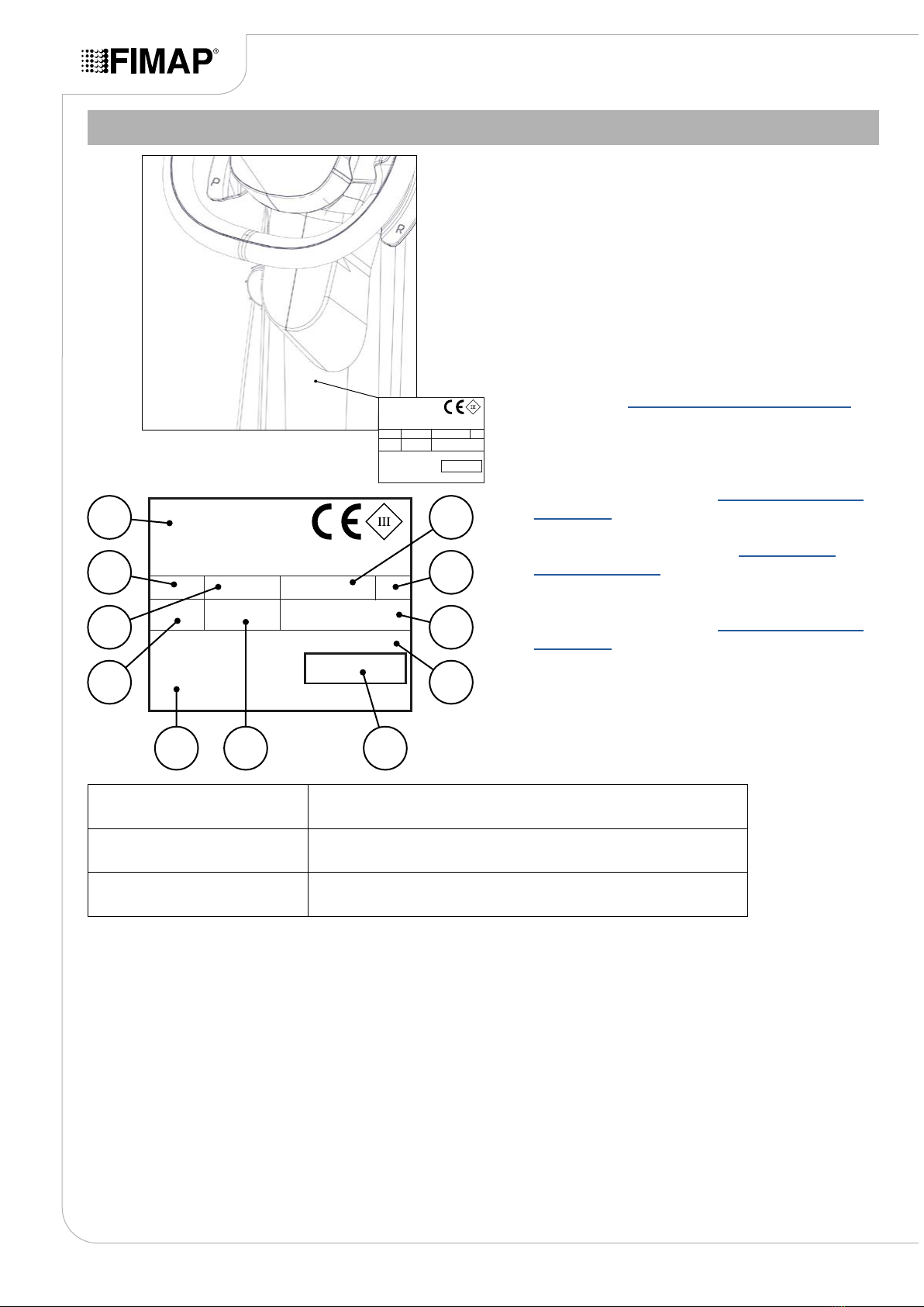
SERIAL NUMBER PLATE ...................................................................................................................................... 8
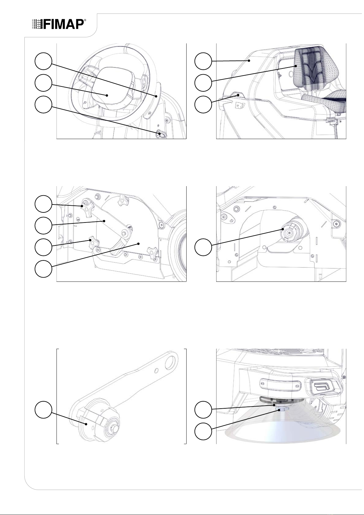
MAIN MACHINE COMPONENTS.......................................................................................................................... 9
STANDARD COMPONENTS ................................................................................................................................. 9
OPTIONAL COMPONENTS................................................................................................................................. 11
TECHNICAL DATA .............................................................................................................................................. 15
SYMBOLS USED ON THE MACHINE ................................................................................................................ 16
LABELS USED ON THE MACHINE.................................................................................................................... 18
CONTROL STATION............................................................................................................................................ 24
DASHBOARD....................................................................................................................................................... 25
CONTROL DISPLAY ........................................................................................................................................ 25
TOUCH SCREEN........................................................................................................................................... 26
PEDALBOARD..................................................................................................................................................... 27
MACHINE PREPARATION .................................................................................................................................. 27
HANDLING THE PACKAGED MACHINE ............................................................................................................ 27
HOW TO UNPACK THE MACHINE ..................................................................................................................... 28
MACHINE SAFETY.............................................................................................................................................. 30
HOW TO MOVE THE MACHINE.......................................................................................................................... 31
TYPE OF BATTERY TO BE USED ...................................................................................................................... 32
BATTERY MAINTENANCE AND DISPOSAL....................................................................................................... 32
INSERTING THE BATTERIES IN THE MACHINE............................................................................................... 32
RECHARGING THE BATTERIES ........................................................................................................................ 33
WITHOUT AN ON-BOARD BATTERY CHARGER .......................................................................................... 33
WITH AN ON-BOARD BATTERY CHARGER.................................................................................................. 34
ADJUSTING THE DRIVING POSITION............................................................................................................... 35
ASSEMBLING THE CENTRAL BRUSH............................................................................................................... 35
ASSEMBLING THE SIDE BRUSHES .................................................................................................................. 37
ASSEMBLING THE VACUUM WAND FILTER BAG ............................................................................................ 38
WORK PREPARATION CHECKLIST.................................................................................................................. 39
WORKING PROGRAMS...................................................................................................................................... 40
ECO MODE WORKING PROGRAM.................................................................................................................... 40
MANUAL MODE WORKING PROGRAM............................................................................................................. 41
ZONE MODE WORKING PROGRAM.................................................................................................................. 43
POWER MODE WORKING PROGRAM.............................................................................................................. 44
WORKING MODE................................................................................................................................................ 45
TRANSFER WORKING MODE............................................................................................................................ 45
SWEEPING MODE .............................................................................................................................................. 46
STARTING WORK ............................................................................................................................................... 48
BATTERY BOX CHARGE LEVEL INDICATOR.................................................................................................... 51
HOUR METER ..................................................................................................................................................... 52
EMPTYING THE DEBRIS HOPPER.................................................................................................................... 52
ADDITIONAL FUNCTIONS ................................................................................................................................. 54
REGULATING THE FORWARD SPEED.............................................................................................................. 54
SELECTING THE FILTER SHAKER METHOD ................................................................................................... 55
MANUAL FILTER SHAKER USE ..................................................................................................................... 55
AUTOMATIC FILTER SHAKER USE ............................................................................................................... 55
ADJUSTING THE VACUUM MOTOR PERFORMANCE LEVEL ......................................................................... 56
ADJUSTING THE PRESSURE EXERTED ON THE BRUSH .............................................................................. 56
- 3 -

BUZZER ............................................................................................................................................................... 57
SERVICE LIGHTS................................................................................................................................................ 57
WORKING HEADLIGHTS.................................................................................................................................... 57
SIDE BRUSH........................................................................................................................................................ 58
EMERGENCY BUTTON....................................................................................................................................... 59
BRAKING CONTROL........................................................................................................................................... 59
REVERSE ............................................................................................................................................................ 60
REAR VIEW VIDEO CAMERA............................................................................................................................. 61
ALARM SCREEN ................................................................................................................................................. 62
TUTORIALS ......................................................................................................................................................... 63
OPTIONAL FUNCTIONS ..................................................................................................................................... 65
BLUE SAFETY LIGHT.......................................................................................................................................... 65
TAG INSERTION.................................................................................................................................................. 65
SOS DEVICE........................................................................................................................................................ 66
VACUUM WAND .................................................................................................................................................. 67
AT THE END OF THE WORK.............................................................................................................................. 68
MAINTENANCE PLAN ........................................................................................................................................ 68
ROUTINE MAINTENANCE.................................................................................................................................. 73
CLEANING THE RUBBER BLADES OF THE FRONT DUST GUARD KIT (OPTIONAL) ................................... 73
CLEANING THE RUBBER BLADES OF THE CENTRAL BRUSH DUST GUARD.............................................. 73
CLEANING THE CENTRAL BRUSH.................................................................................................................... 75
CLEANING THE SIDE BRUSHES ....................................................................................................................... 76
CLEANING THE PANEL FILTER ......................................................................................................................... 76
CLEANING THE POCKET FILTER (OPTIONAL)................................................................................................. 77
CLEANING THE VACUUM WAND FILTER BAG (OPTIONAL) ........................................................................... 77
CLEANING THE VACUUM WAND INLET AIR FILTER (OPTIONAL) .................................................................. 78
EXTRAORDINARY MAINTENANCE WORK ...................................................................................................... 79
REPLACING THE CENTRAL BRUSH ................................................................................................................. 80
ASSEMBLING THE SIDE BRUSHES .................................................................................................................. 81
DISPOSAL ........................................................................................................................................................... 82
CHOOSING AND USING BRUSHES .................................................................................................................. 82
TROUBLESHOOTING......................................................................................................................................... 84
THE MACHINE DOES NOT START..................................................................................................................... 84
THE BATTERY BOX IS NOT COMPLETELY CHARGED.................................................................................... 84
THE MACHINE HAS A VERY LOW WORK AUTONOMY.................................................................................... 84
THE MACHINE DOES NOT MOVE ..................................................................................................................... 85
THE MACHINE DOES NOT CLEAN CORRECTLY ............................................................................................. 85
THE VACUUM SYSTEM DOES NOT VACUUM CORRECTLY ........................................................................... 85
THE MACHINE DOES NOT VACUUM CORRECTLY.......................................................................................... 85
EXCESSIVE DUST PRODUCTION ..................................................................................................................... 86
EC DECLARATION OF CONFORMITY .............................................................................................................. 87
UKCA DECLARATION OF CONFORMITY ......................................................................................................... 89
- 4 -

GENERAL DESCRIPTION
The descriptions contained in this document are not binding. The company therefore reserves the right to make
any modications at any time to elements, details, or accessory supply, as considered necessary for reasons of
improvement or manufacturing/commercial requirements. The reproduction, even partial, of the text and drawings
contained in this document is prohibited by law.
The company reserves the right to make any technical and/or supply modications. The images are for
reference purposes only, and are not binding in terms of design and supply.
DEFINITION OF LEVELS OF WARNING
DANGER: indicates an imminent dangerous situation that, unless avoided,
will result in death or serious injuries.
WARNING: Indicates a potentially dangerous situation that, unless avoided,
could cause death of serious injury.
ATTENTION: Indicates a potentially dangerous situation that, unless
avoided, could cause slight or moderate injuries.
NB: instructs the reader to pay particular attention to the topic that follows.
GENERAL SAFETY REGULATIONS
Before using the machine, please read the following document
carefully and follow the instructions contained herein, along
with the instructions in the document supplied with the machine
itself, "GENERAL SAFETY REGULATIONS" (document number
10083659).
- 5 -

SYMBOLS USED IN THE MANUAL
Open book symbol with an "i":
Indicates the need to consult the instruction manual.
Open book symbol:
Tells the operator to read the user manual before using the device.
Covered place symbol:
The operations preceded by this symbol must always be carried out in a dry, covered area.
Information symbol:
Indicates additional information for the operator, to improve the use of the device.
Warning symbol:
Carefully read the sections preceded by this symbol meticulously following the instructions indicated
for the safety of the operator and the device.
Danger symbol (moving carriages):
Indicates that the packed product should be handled with suitable carriages that conform to legal
requirements.
Symbol indicating the compulsory use of protective gloves:
Indicates that the operator should always wear protective gloves, to avoid the risk of serious injury
to his hands from sharp objects.
Recycling symbol:
Tells the operator to carry out the operations in compliance with environmental regulations in force
in the place where the appliance is being used.
Disposal symbol:
Carefully read the sections marked with this symbol for disposing of the appliance.
TECHNICAL DESCRIPTION
The FSR7 is a ride-on sweeping machine powered by
batteries with an output voltage of 24V. It is designed to
clean tiled, cement or tarred ooring, both indoors and
outdoors.
The FSR7 must be used on dry surfaces, but can also
work on wet surfaces if necessary as long as the vacuum
is not activated.
This sweeping machine features a central brush for
collecting brushed-up material, one or two side brushes
for cleaning along edges and in corners, a vacuum
system with lter to avoid raising dust, and a debris
hopper that is moved manually by the operator.
The machine must be used only for this purpose.
- 6 -

INTENDED USE
This machine is designed and built to clean both indoor and outdoor ooring surfaces in tile, cement and asphalt.
They are intended exclusively for professional use by a qualied operator in industrial, commercial and public
contexts, in guaranteed safe conditions.
ATTENTION: the sweeping machine is not designed to clean carpets or rugs. It is not suitable for use
in closed places and should be used in open but covered areas (it must not be used in the rain or underneath
jets of water).
IT IS FORBIDDEN: to use the sweeping machine in places with an explosive atmosphere or to collect
hazardous dust or inammable liquids. In addition, it must not be used for transporting people or objects.
SAFETY
Operator cooperation is paramount for accident prevention. No accident prevention programme can be eective
without the full cooperation of the person directly responsible for machine operation. The majority of occupational
accidents that happen either in the workplace or whilst moving are caused by failure to respect the most basic
safety rules. An attentive, careful operator is most eective guarantee against accidents and is fundamental
in order to implement any prevention programme.
REGULATIONS
All references to forwards and backwards, front and rear, right and left indicated in this manual should
be understood as referring to the operator in a driving position with his hands on the steering wheel.
- 7 -

SERIAL NUMBER PLATE
111
210
39
48
57 6
The serial number plate is located near the driver's
seat, at the rear of the steering column, and indicates
the machine's general characteristics, including its
serial number. The serial number is a very important
piece of information and should always be provided
together with any request for assistance or when
purchasing spare parts. The serial number plate
contains the following information:
1. The weight of the batteries that power the
machine (expressed in kg).
2. The IP protection rating of the machine.
3. The value, in kg, of the GVW (Gross Vehicle
Weight). See “TECHNICAL DATA” on page 15.
4. The machine ID code.
5. The machine serial number.
6. The machine ID name.
7. The value, expressed in W, of the nominal power
used by the machine. See “TECHNICAL DATA”
on page 15.
8. The value, expressed in %, of the maximum
gradeability during work. See “TECHNICAL
DATA” on page 15.
9. The year of machine manufacture.
10. The value, expressed in V, of the nominal voltage
used by the machine. See “TECHNICAL DATA”
on page 15.
11. The commercial name of the machine, and the
manufacturer's address.
Fill in the following table at the time of delivery and/
or installation, so it can be used as a future reference
when necessary.
MACHINE ID NAME
SERIAL NUMBER
DATE OF DELIVERY AND/
OR INSTALLATION
- 8 -

MAIN MACHINE COMPONENTS
STANDARD COMPONENTS
- 9 -
1 Right side brush
2Traction wheel
6 Right-hand maintenance carter
7Rear wheel
10 Service brake pedal
11 Left-hand maintenance carter
8 Debris hopper
9Debris hopper retainer lever
12 Steering wheel
13 Activation lever for extra-pressure
function (central brush)
14 Horn button
3 Battery cut-out button
4Front ap lifting pedal
5Accelerator pedal
1
6
10
8
13
12
4
2
7
11
9
14
5
3

- 10 -
18 Upper body
19 Operator's seat
20 Upper body rotation handle
15 Reverse activation lever
16 Control display
17 Main machine switch
21 Locking knob for central brush lifting
lever
22 Central brush lifting lever
23 Locking knob for central brush side
inspection carters
24 Central brush side inspection carters
25 Central brush towing hook
26 Central brush idle hook 27 Side brush retainer plate
28 Side brush locking knob
1916
22
1815
21
2017
23 25
26 27
24
28

OPTIONAL COMPONENTS
- 11 -
29 Vacuum compartment cover
30 Vacuum compartment cover locking
knob
31 Vacuum compartment cover rotation
handle
33 Battery compartment
34 Battery cable connector (version
without on-board battery charger)
35 Rear view video camera
32 Panel lter
30
34
29
33 33
32
31
36 Left side brush 37 Integrated vacuum cleaner kit
38 Blinking light
38
36
37

- 12 -
39
Locking knob for compartment cover of
the lter bag in the integrated vacuum
cleaner kit
40 Compartment cover of the lter bag in
the integrated vacuum cleaner kit
43 Front anti-dust skirt
45 Support for bag of the cleaning
accessory kit
41 Support for the motor inlet air lter in
the integrated vacuum cleaner kit
42 Motor inlet air lter in the integrated
vacuum cleaner kit
44 Front bumper kit
42
44
40
43
45
39
41
46 Support basin for bottles in the
cleaning accessory kit
46

TECHNICAL DATA
TECHNICAL DATA UM
[SI]
FSR7
PLUS
Rated voltage
[IEC 60335-2-72; IEC 62885-9] V 24
Nominal input power
[IEC 60335-2-72; IEC 62885-9] KW 1.9
Working gradeability with GVW
[IEC 60335-2-72; IEC 62885-9] %12.5
Machine working weight (gross weight - GVW)
[IEC 60335-2-72; IEC 62885-9] kg 685
Weight during transport
[IEC 60335-2-72; IEC 62885-9] kg 420
Machine dimensions during working phase
(length; height; width) mm
1610
1290
1020
Operator station sound pressure level (LpA)
[IEC 60335-2-72; IEC 62885-9; ISO 11201] dB (A) 69
Sound power level (LwA)
[IEC 60335-2-72; IEC 62885-9; ISO 3744] dB (A) 85.8
Uncertainty KpAdB (A) ±1.5
Hand-arm vibrations
[IEC 60335-2-72; IEC 62885-9; ISO 5349-1] m/s21.34
Whole-body vibrations
[IEC 60335-2-72; IEC 62885-9; ISO 2631-1] m/s20.3
Vibration measurement uncertainty ±4%
TECHNICAL DATA UM
[SIB]
FSR7
PLUS
Rated voltage
[IEC 60335-2-72; IEC 62885-9] V 24
Nominal input power
[IEC 60335-2-72; IEC 62885-9] KW 1.9
Working gradeability with GVW
[IEC 60335-2-72; IEC 62885-9] %12.5
Machine working weight (gross weight - GVW)
[IEC 60335-2-72; IEC 62885-9] lb 1510.17
Weight during transport
[IEC 60335-2-72; IEC 62885-9] lb 925.94
Machine dimensions during working phase
(length; height; width) in
63.38
50.78
40.15
Operator station sound pressure level (LpA)
[IEC 60335-2-72; IEC 62885-9; ISO 11201] dB (A) 69
Sound power level (LwA)
[IEC 60335-2-72; IEC 62885-9; ISO 3744] dB (A) 85.8
Uncertainty KpAdB (A) ±1.5
Hand-arm vibrations
[IEC 60335-2-72; IEC 62885-9; ISO 5349-1] m/s21.34
Whole-body vibrations
[IEC 60335-2-72; IEC 62885-9; ISO 2631-1] m/s20.3
Vibration measurement uncertainty ±4%
NB: for all other technical data, contact the FIMAP service centre of reference or the one closest to you,
or visit the website www.map.com.
- 15 -

SYMBOLS USED ON THE MACHINE
- 16 -
Reverse gear activation/deactivation lever position symbol:
applied to the reverse activation/deactivation lever. See “REVERSE” on page 60.R
PExtra pressure activation/deactivation lever position symbol:
Used on the extra brush head pressure activation-deactivation lever. See “POWER MODE
WORKING PROGRAM” on page 44

AUTO
“AUTO” symbol on blinking light selector lever:
applied to the carter of the electric system panel, to show where to position the blinking light
control lever so the LEDs switch on automatically when the microswitches that command them are
deactivated. See “SERVICE LIGHTS” on page 57.
OFF
“OFF” symbol on blinking light selector lever:
applied to the carter of the electric system panel, to show where to position the blinking light control
lever so the LEDs are always switched o. See “SERVICE LIGHTS” on page 57.
ON
“ON” symbol on blinking light selector lever:
applied to the carter of the electric system panel, to show where to position the blinking light control
lever so the LEDs are always switched on. See “SERVICE LIGHTS” on page 57.
- 17 -

- 20 -
Main machine switch label: applied on the right side of the steering column, to indicate the location
of the machine's main switch.
Prohibition to vacuum hazardous elements label: applied to the back of the steering column
to indicate that it is strictly prohibited to vacuum up incandescent particles or ammable and/or
explosive powders and/or liquids with the machine, and to operate the machine in their vicinity.
Serial number plate: applied to the back of the steering column. Shows the general machine
characteristics, including the serial number. See “SERIAL NUMBER PLATE” on page 8.
Horn button label: applied to the left side of the steering column to identify the machine's horn
button.
Label indicating the need to read the Use and Maintenance Manual: applied on the left side
of the steering column, to indicate the need for the user to read the user and maintenance manual
before operating the machine.
Other manuals for FSR7 PLUS
1
Table of contents
Other Fimap Blower manuals