Fimer ELECTRA DC Station 60 User manual

Installation manual
FIMER ELECTRA DC Station
60-150 kW

SAFETY INSTRUCTION
ATTENTION –AThis manual contains important safety instructions that must be followed
during the installation and maintenance of the equipment.
KEEP THIS MANUAL
READ THE MANUAL –EKeep this document in a safe place for easy access during
installation and maintenance.
THE INSTALLER SHOULD READ THIS DOCUMENT IN ITS ENTIRETY BEFORE INSTALLING THE
EQUIPMENT
READ THE MANUAL –EOperators are required to read this manual and adhere to the
instructions contained therein.
FIMER cannot be held liable for damages caused to persons and/or property, or to the equipment, if
the conditions described below have not been met.
The purpose of this document is to support qualified technicians, who have received adequate training
and/or have demonstrated adequate skills and knowledge in the construction, installation, operation
and maintenance of electrical equipment.
The warranty requirements are contained in the Terms and Conditions of Sale section included in the
purchase order for this product.
NOTE –DAny modification not approved by FIMER will immediately void the product
guarantee.
WARRANTY AND DELIVERY CONDITIONS
The warranty conditions are considered valid if the customer complies with the instructions contained
in this manual; any deviation from the warranty conditions, with respect to what is described below,
must be expressly indicated in the purchase order.
FIMER declares that the equipment complies with the legal provisions currently in force in the country
of installation and has issued a relevant declaration of conformity.
FIMER assumes no responsibility for any failure to comply with the instructions for correct installation
and may not be held responsible for systems upstream or downstream of the equipment supplied.
FORBIDDEN –HModifications to the equipment are strictly forbidden. Any modification,
manipulation or alteration to the hardware or software not expressly agreed with the manufacturer
will result in the immediate cancellation of the guarantee.
Given the extensive combinations of system configurations and possible installation settings, it is
essential to check the following before proceeding with installing the product: adequate space for
housing the equipment, airborne noise produced by the environment and possible conditions for
flammability.
FIMER cannot be held responsible for defects or malfunctions deriving from: improper use of the
equipment; deterioration due to transport or particular environmental conditions; incorrect or missing
maintenance; tampering or unsafe repairs; use or installation by unqualified persons.
FIMER is not responsible for any loss of the equipment, or part of it, that is not used according to the
regulations and laws in force in the country of installation.

PURPOSE AND STRUCTURE OF THE DOCUMENT
This use and maintenance manual is a guide that will allow you to work safely and perform the
necessary operations to keep the equipment in good working order.
ATTENTION –AIf the equipment is used in a manner not specified in this manual, the
protection provided by the equipment may be compromised.
The document was originally written in Italian; therefore, in case of inconsistencies or doubt, please
ask FIMER S.p.A. for the original document.
LIST OF DOCUMENTS IN APPENDIX
READ THE MANUAL –EIn addition to this user manual, you can consult and download the
product documentation by visiting www.fimer.com.
READ THE MANUAL –EThis document contains only the information deemed necessary
for the routine use and maintenance of the equipment.
SKILLS AND REQUIREMENTS FOR THE OPERATOR AND MAINTENANCE PERSONNEL
READ THE MANUAL –EThe personnel assigned to use, maintain and install the equipment
must be qualified by FIMER (by means of a letter attesting to their qualification) for the
activities described and must reliably demonstrate their ability to correctly interpret the
contents of this manual.
ATTENTION –AInstallation must be carried out by FIMER qualified installers and/or
FIMER authorized electricians in compliance with the regulations in force in the country of
installation and in accordance with all the safety standards for carrying out electrical work.
FORBIDDEN –HThe installation or maintenance of the product may not be entrusted to
unqualified persons or persons in an altered physical or mental state.
ATTENTION –AThe customer bears civil responsibility for the qualifications and mental or
physical state of personnel interacting with the equipment. Such personnel must always use
the personal protective equipment (PPE) required by the laws of the country of destination
and by their employer’s instructions.

Table of content
1. General informations
1.1 .........................................................................................................Field of use 6
1.2...................................................................................Symbols and definitions 8
1.3...........................................................Product dimensions and characteristics 9
1.4...............................................................................................................Support 10
2. Safety and equipment
2.1 .................................................................................................Safety warnings 11
2.2 ...................................................................................................Compliant use 11
2.3............................................................................................... Product handling 12
3. Installation
3.1 ..................................................................................Preparing for installation 13
3.2....................................................................................................Tools required 14
3.3.............................................................................................. Package contents 14
3.4...................................................................................... Space and positioning 14
3.5.......................................................................................................... Unpacking 15
3.6................................................................................Anchor device installation 16
3.6.1 ......................................................................Installation on existing ground 17
3.6.2 ....................................................................... Installation in fresh concrete 18
3.7......................................................................................................Station fixing 19
3.8...........................................................Power and grounding cord connection 21
4. First startup and configuration
5. Instruction for use
5.1 ............................................................................Operations prior to charging 32
5.2......................................................................................................Use interface 32
5.3......................................................................... Errors or authorisation failure 37

6. Troubleshooting
7. Maintenance
7.1 ........................................................................................ Maitenance schedule 41
8. Commissioning
9. Decommissioning and disposal
10. Technical data

6
1. General informations
FIMER ELECTRA DC Station is the DC charging station for powering electric vehicles ideal for public
and semi-public applications: it is available in configurations which integrate the 2 charging modes:
DC (Mode 4 in accordance with IEC 61851-23-24 standard) and AC (Mode 3 in accordance with IEC
61851-1 standard).
Equipped with 3 charging points 1 AC with Type 2 plug (in accordance with IEC 61851-1 standard) and
2 DC with Type CCS plug (in accordance with IEC 61851-23 and 24 standard) and CHAdeMO (in
accordance with IEC 61851-24 standard) according to the chosen configuration.
Characterized by significant robustness and ease of use, this device allows the simultaneous charging
of three electric vehicles with a maximum power range between 103 kW and 193 kW according to the
product version:
• 103 kW (60 kW for DC and 43 kW for AC)
• 133 kW (90 kW for DC and 43 kW for AC)
• 163 kW (120 kW for DC and 43 kW for AC)
• 193 kW (150 kW for DC and 43 kW for AC)
ATTENTION –APrepare and size the entire power supply circuit in accordance with the
local and international standards in force, according to the product configuration and the
chosen power.
ATTENTION –AThis document describes how to install, configure and maintain the product.
ATTENTION –AA description of the equipment features is provided to help identify its main
components and specify the technical terminology used in the manual.
READ THE MANUAL –EThis chapter contains information on the model, equipment details,
technical characteristics and data, dimensions and the identification of the equipment.
1.1 Field of use
FIMER is not liable for damages of any kind that may arise from incorrect or reckless operations.
FORBIDDEN –HThe equipment may not be used for a purpose that does not conform to that
envisaged in the field of use. The equipment must not be installed by inexperienced personnel,
or even by experienced personnel if operations are performed on the equipment that are not in
accordance with this manual and the accompanying documentation.
This equipment is a charging station for electric vehicles; the following classification (according to IEC
61851-1, 23 and 24) identifies its features:
• Power supply: permanently connected to the AC power supply
• Output: AC and DC current
• Environmental conditions: Non-restricted access
• Device for places with free access
• Fixed installation ground-mounted
1

7
1
• Protection against electric shock: Class I
• Charging type: Mode 3 according to IEC 61851-1 and Mode 4 according to IEC 61851-23 and IEC
61851-24.
ATTENTION –AWhen installing in TN-earthing systems, there may be additional specific
local regulations regarding system safety and failure protection that the installer must
understand and implement.
ATTENTION –AThe device may only be connected to the mains in countries for which it has
been certified/approved.
IT IS STRICTLY FORBIDDEN:
FORBIDDEN –HInstalling the equipment in particularly flammable environments or in adverse or
non-authorized environmental conditions.
FORBIDDEN –HUsing the equipment with faulty or disabled safety devices.
FORBIDDEN –HUsing the equipment or parts of the equipment by connecting it to other
machines or equipment, unless expressly allowed.
FORBIDDEN –HModifying operating parameters not accessible to the operator and/or parts of
the equipment to adjust its performance or change its isolation status.
FORBIDDEN –HCleaning the product with corrosive products that could damage parts of the
equipment or generate electrostatic charges.
FORBIDDEN –HUsing or installing the appliance or parts thereof without having read and
understood the contents of the use and maintenance manual.

8
1.2 Symbols and definitions
In this manual and/or in some cases on the equipment, dangerous zones/components are indicated
by signs, labels, symbols or icons.
Symbol Description
GENERAL WARNING
THE ORIGINAL MANUAL OR OTHER ADDITIONAL DOCUMENTATION MUST BE
CONSULTED
PROHIBITION OR RESTRICTIONS
The operations described must be carried out using the clothing
and/or protective equipment provided by the employer
The products should not be disposed of with household waste,
but collected in a different manner as, although not composed
of materials harmful to health, they are made of recyclable materials
Hazard-warning signal: presence of electrical voltage
Obligation signal: read the instructions
The installation of the electronic device should be performed
only by qualified personnel
9
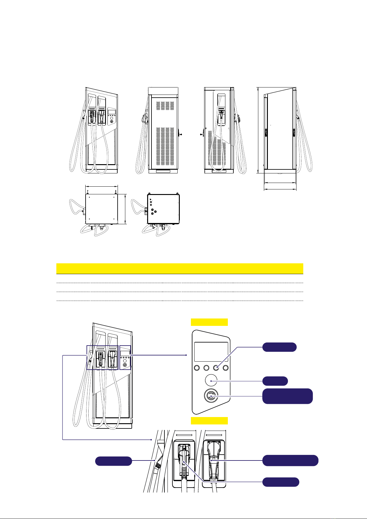
1.3 Product dimensions and characteristics
1853
672
694
643,5
697
FRONT VIEW SIDE VIEW LH REARSIDE VIEW RH
TOP VIEW BOTTOM VIEW
FIMER ELECTRA DC Station 60 90 120 150
Weight [kg] 333 kg 355 kg 378 kg 400 Kg
Dimensions LxHxW [mm] 697 x 1853 x 644 mm
Dimensions with plug [mm] 740 x 1853 x 779 mm
Display
Plug
Emergency
button
RFID
Buttons
CCS Plug
CHAdeMO Plug
AC Plug

10
1.4 Support
For any further information or request for support, FIMER is available through the dedicated section
of the website www.fimer.com or by writing to service.emobility@FIMER.com.

11
2. Safety and equipment
2.1 Safety warnings
ATTENTION –AThe installation and start-up phases of the device must be carried out
exclusively by qualified personnel, able to identify hazards and act safely.
ATTENTION –AThe phases of maintenance, repair or subsequent repositioning must also
be carried out only by qualified personnel: there are no components that can be repaired by
the user or maintained independently.
WARNING –BChildren or persons not deemed capable of assessing the risks involved in
the installation must not handle the product.
WARNING –BBoth domestic and non-domestic animals must be kept away from the
equipment.
WARNING –BTotal or partial non-compliance with the indications contained in this document
can lead to serious or fatal injuries.
WARNING –BThe qualified installer must always ensure that the installation takes place in
accordance with the local regulations in force at the time of installation.
2.2 Compliant use
ATTENTION –AThe device requires grounding by a dedicated equipotential cable, to be
connected in the grounding terminal inside the device.
ATTENTION –AIn any case, before installation, it is necessary to verify that the power
supply system is fully compliant with the state of art and provided by qualified personnel in
accordance with local and international regulations in force.
ATTENTION –AThe device is only safe to use if it is used as intended.
ATTENTION –ADifferent uses and unauthorized modifications to the equipment or any of
its components are therefore forbidden and are thus considered non-compliant.
ATTENTION –AThe equipment is designed to be connected and to communicate information
and data via a network interface. Users are responsible for consistently providing and ensuring
a secure connection between the product and their data network or any other network (as
applicable). Users should establish and maintain all appropriate measures (such as, but not
limited to, installing firewalls, applying authentication measures, encrypting data, installing
anti-virus programs, etc.) to protect the product, the network, their system and interface
against any type of security breach, unauthorized access, interference, intrusion, loss or
theft of data or information. FIMER and its affiliates are not liable for damages or losses
related to such security breaches, any unauthorized access, interference, intrusion, leakage
or theft of data or information. The data, examples and diagrams in this manual are included
only with the aim of describing the product and should not be considered as a guaranteed
declaration of ownership. All persons responsible for installing the equipment indicated in
this manual must ensure that each intended installation is suitable and acceptable, including
compliance with any applicable safety or other operational requirements. In particular,
2

12
any risk in applications where a system or product failure would create a risk of damage
to property or persons (including but not limited to personal injury or death) will be the
exclusive responsibility of the person or entity installing the equipment; those responsible
are encouraged to ensure that all measures are taken to exclude or mitigate such risks.
This document has been carefully checked by FIMER, but deviations cannot be completely
ruled out. If errors are detected, the reader is kindly requested to notify FIMER. Other than
under explicit contractual commitments, in no event shall FIMER be responsible or liable
for any loss or damage resulting from the use of this manual or from the installation of the
equipment.
ATTENTION –AThe product is not suitable for free display on the Internet. To ensure
maximum security of information and operation, the device must remain protected from any
attempt to contact it via the Internet and therefore a communication can only be originated
from the device and not vice versa.
ATTENTION –AIf you require further information, support or cybersecurity reports, you can
write to itteb.cybersecurity@fimer.com.
2.3 Product handling
WARNING –BThe total weight of the product without packaging is approximately 333 ÷ 400
kg (depending on the version): make sure to use a suitable tool for handling.
WARNING –BTransport and store in a dry place away from heat sources (as specified in the
technical specifications), only in the original packaging.

13
3. Installation
ATTENTION –AFailure to observe the instructions provided in this manual can cause
serious damage to both the product and the installer (in the most serious cases, injuries
can be fatal). Before proceeding with the installation, start-up and use of the product, you
should carefully read the instructions in this manual. FIMER recommends using experienced
professionals, who comply with current regulations, to install the product correctly.
3.1 Preparing for installation
Before installing, make sure that:
• Input power supply is completely switched off and remains off until installation is completed.
• The work area is adequately marked and isolated (access to people not required for the work must
be prevented).
• Installation should not be done with wet hands and no water jet may be directed at the product.
• Do not install in conditions of rain, fog, or high humidity.
•
The packaging of the product is perfectly intact and without obvious damage (if the product is
damaged, contact your seller or request support at www.fimer.com).
•
The product and all components (including cords) are perfectly intact and without any defects or
obvious faults.
ATTENTION –ATo ensure the correct operation of the product, referring to local regulations
in force, calculate the distance between the power supply panel and the installation site
properly to determine the voltage drop, cord thickness and existing load, which are useful
for identifying the maximum operating current.
ATTENTION –AThe entire electrical power supply system to which the product is connected
must first be correctly sized by a qualified professional. The electrical data of the device,
which must be consulted for the correct sizing of the power supply system, are the data on
the label of the device itself.
ATTENTION –AWhen installing this product, you must comply with all local and international
standards for the construction and installation of electrical/electronic equipment, including
but not limited to IEC 60364-1 and IEC 60364-5-52.
The power supply system must meet the following requirements:
• TN or TT system, in both cases with PE cord
• Three-phase power supply: 400 VAC ± 10% - 50/60 Hz
3

14
3.2 Tools required
• Cutter
• Flathead screwdriver and Phillips screwdriver or screwdriver
• Torque wrench for hexagonal screws
• Marker/pencil
• Drill and drill bit suitable for the material of the fixing surface to be drilled to install M12 anchors
• Hexagonal wrenches
• Wire stripper
• Forklift truck or crane and respective belts for the handling and positioning
ATTENTION –AFIMER declines all responsibility for damages to property or persons
deriving from the use of these instruments. The installation must be carried out by qualified
personnel and in accordance with the regulations in force for the installation of electrical
equipment.
3.3 Package contents
• N.1 FIMER ELECTRA DC Station
• N.4 M12 plugs with relative threaded bars and nuts
• N.4 stainless steel M12x20mm screws (DIN 933) + N.4 M12 stainless steel washers 37x13 sp 3 mm
(DIN 9021)
• N.2 fixing plates
• N.2 Keys for opening the lateral door
• Template for holes and anchor devices installation in fresh concrete
• Installation manual
IF REQUESTED IN ORDERING PHASE, IN ADDITION TO WHAT LISTED ABOVE, THE STATION
IS EQUIPPED WITH:
• N.1 Plate for fresh concrete installation
• N.4 Anchor devices M10 with welded washer
• N.4 hexagonal sleeves M10
• N.1 or more user RFID card(s)
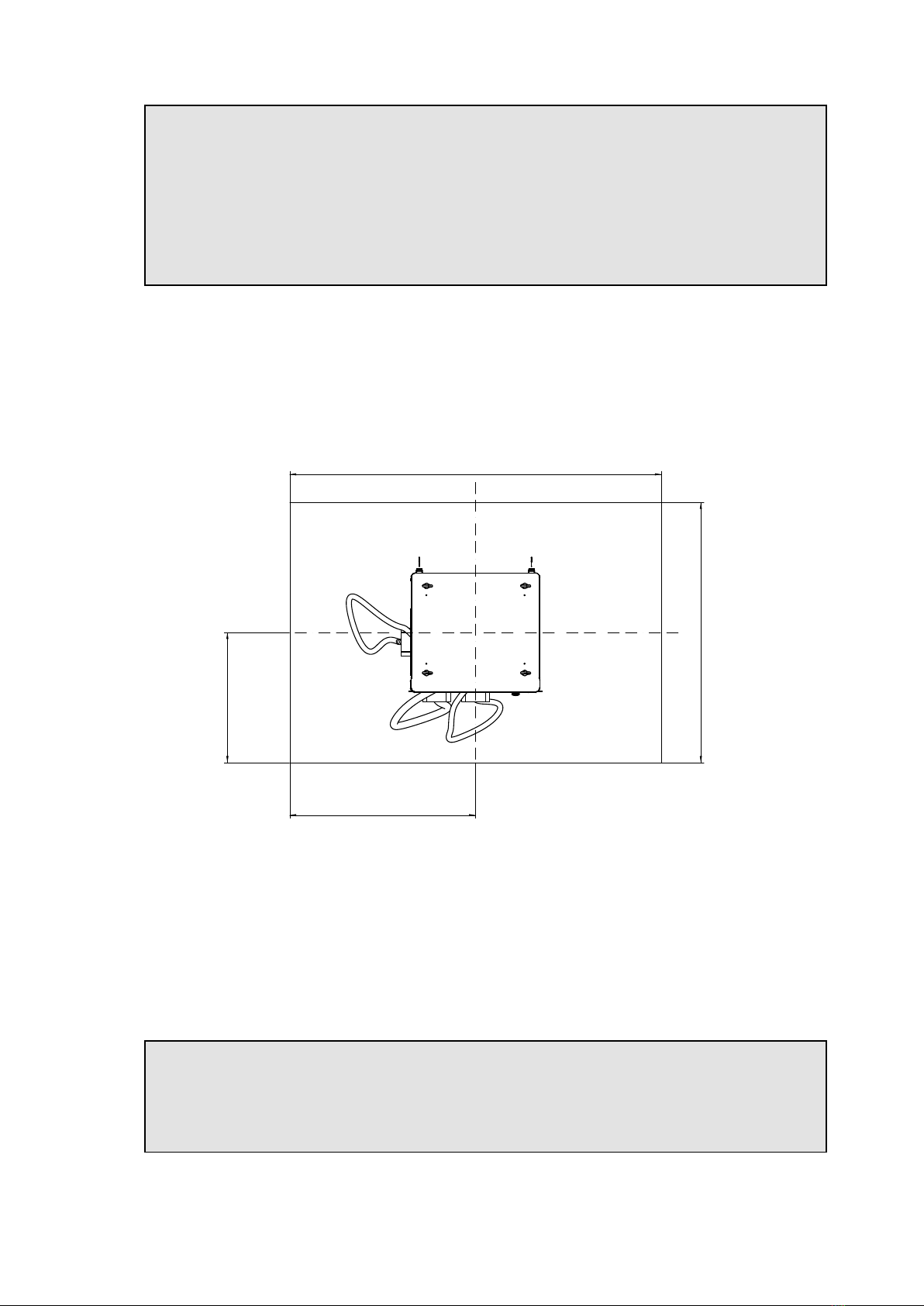
3.4 Space and positioning
ATTENTION –ABefore choosing a location for this product, consult the electric vehicle’s
manual and follow any applicable guidelines.
ATTENTION –AEnsure that there are no heat sources, flammable substances, or
electromagnetic sources in the installation area either during the product installation phase
or throughout its life.
ATTENTION –AIn addition, the installation site must be sufficiently ventilated to ensure
proper heat dissipation.
ATTENTION –AFor mobile cellular versions of the product, make sure the selected area
has cellular reception coverage.
ATTENTION –ABefore installation, make sure that the environmental conditions (such
as temperature, altitude and humidity) according to section 1.1 and 10 of the product
specifications are met.
ATTENTION –AFor locations where the device will be exposed to direct sunlight or weather
for most of the day, it is recommended to install a cover to protect the charging station.
15
ATTENTION –ATo ensure the functionality of the device and to guarantee its correct use
by the user, the space around the device must be free to allow air circulation, maneuvering
the cords, recharging operations by the user and routine and extraordinary maintenance in
safety.
ATTENTION –AIn addition, the space required to park the electric vehicle for recharging
must be taken into consideration.
ATTENTION –AFor locations where the device will be exposed to direct sunlight or weather
for most of the day, it is recommended to install a cover to protect the charging station.
Furthermore:
• Make sure the charging device is protected from collisions by barriers or poles.
• Design the parking layout for easy access to the charging cord.
• Provide a comfortable environment for users, providing safety against vandalism or theft.
• Install the charging device in a location where it can be clearly seen or monitored.
• Install sufficient lighting around the device.
13560
640
690
19470
2000
1400
700
1000
3.5 Unpacking
Before proceeding with the installation of the device, it is necessary to check, upon unpacking, that
the various parts of the device do not present physical damage due to shocks, tears or abrasions.
If any damage is detected, stop the installation procedure immediately and contact technical support
as described in section 1.4.
The various components are protected by packaging and adhesive tapes. Before installation, each
component must be cleared of any traces of dust, the packaging or adhesive tapes.
ATTENTION –AThe following images are for illustrative purposes only; they may not show
all internal components of the product or present negligible differences from the actual
configuration.
ATTENTION –ANotify the carrier and FIMER support immediately if rough handling of the
equipment is suspected or if any damage is found or suspected.

16
ShockWatch and TiltWatch devices indicate if the package
was subject to shock or tip-over
1.Remove the panels and the roof unscrewing the fixing screws.
2.Remove fastening belts (if any).
3.Remove protective film and bumper being careful not to scratch the station surface.
4.Remove the cover plates on both sides underneath the doors, verify the presence of fixing screws
which anchor the station to the pallet. If any, remove the screws and keep the cover plates that must
be used as described in section 3.7.
5.Using a special handling equipment, lift the station from the eyebolts and place it on a horizontal
work plane.
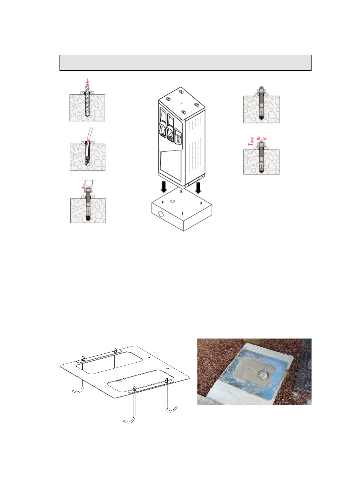
3.6 Anchor device installation
ATTENTION –AThe following images are for illustrative purposes only; they may not show
all internal components of the product or present negligible differences from the actual
configuration.
ATTENTION –AWe suggest the construction of a manhole with dimensions suitable for the
positioning of the DC Station and its plate (in case of installation in fresh concrete), to allow
easier cable entry.
13560
640
690
19470
2000
1400
700
1000
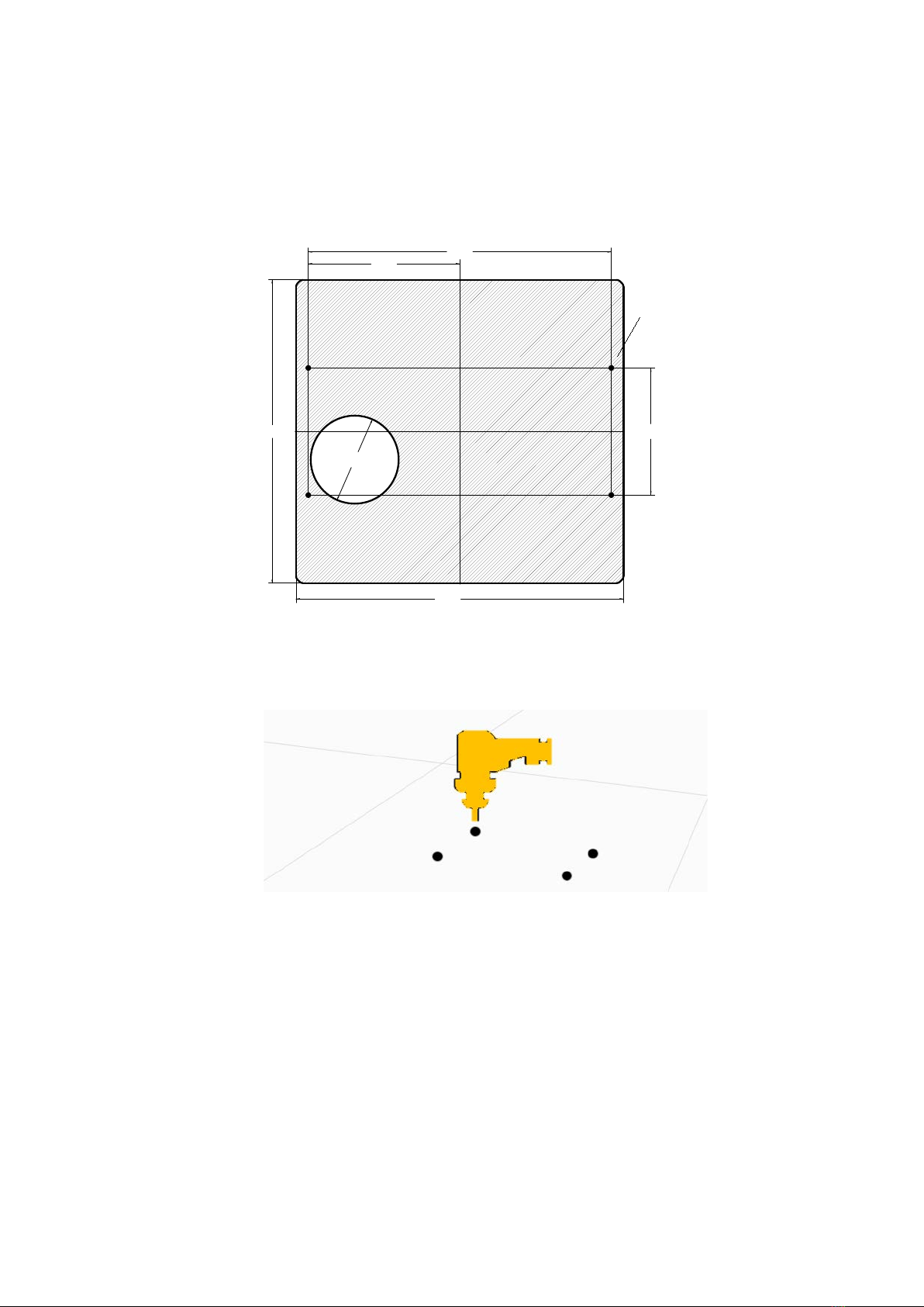
BOTTOM VIEW: Inlet holes positioning
17
3.6.1 Installation on existing ground
1.Place the template on the ground where you want to install the product (in any case respecting the
indications previously provided about positioning) and letting the corrugated pipe come out of the
ground for about 3-5cm.
N° 4 HOLES Ø 8mm
670
620 260
620
310
O180
2.Using the template, make marks on the floor in correspondence of the four (4) present holes.
3.Remove the template and drill holes in the ground at the position of the four (4) marks previously
made with adequate drill bit to position the anchoring devices (M12). The maximum drilling depth is
85 mm, while the minimum support width (concrete) must be at least 168mm. Then, clean the hole
made from any debris of drilling.
4.
If the installer wants to further increase the seal, it is possible to inject in the four (4) holes just made
some resin anchor (or chemical).
5.Remove pre-screwed bolts and washers from the anchor devices.
6.
Insert the four (4) anchor devices into the four (4) holes just drilled so that the threaded parts
protruding from the ground is about 30 mm.
7.
Lift and position the charging station at the corresponding anchor devices (so that the threaded
parts protruding from the ground pass through the pedestal holes).
8.
Adjust the cable gland(s) to pass the cable(multipolar)/cables into it. Finally, tighten the cable
gland(s) once the correct length for connecting the power cables has been sized.
18
9.Fix the station to the ground as shown in section 3.7.
ATTENTION –AThe station cannot be lifted from the bottom once removed from pallet; for
lifting and positioning , use the eyebolts on the roof.
3.6.2 Installation in fresh concrete
1.Attach the anchor bolts to the plate using M10 threaded hexagonal sleeves.
2.
Install the plate with anchor bolts inside the concrete casting, making sure that only the anchor bolts
are submerged, while the horizontal plate must emerge just from the surface.
3.
Once the cement has solidified, using a special handling equipment, place the station above the
installation place, pass the cables from the bottom through the cable entry holes.
4.
Adjust the cable gland(s) to pass the cable(multipolar)/cables into it. Finally, tighten the cable
gland(s) once the correct length for connecting the power cables has been sized.
5.Fix the station to the ground as shown in section 3.7.
19
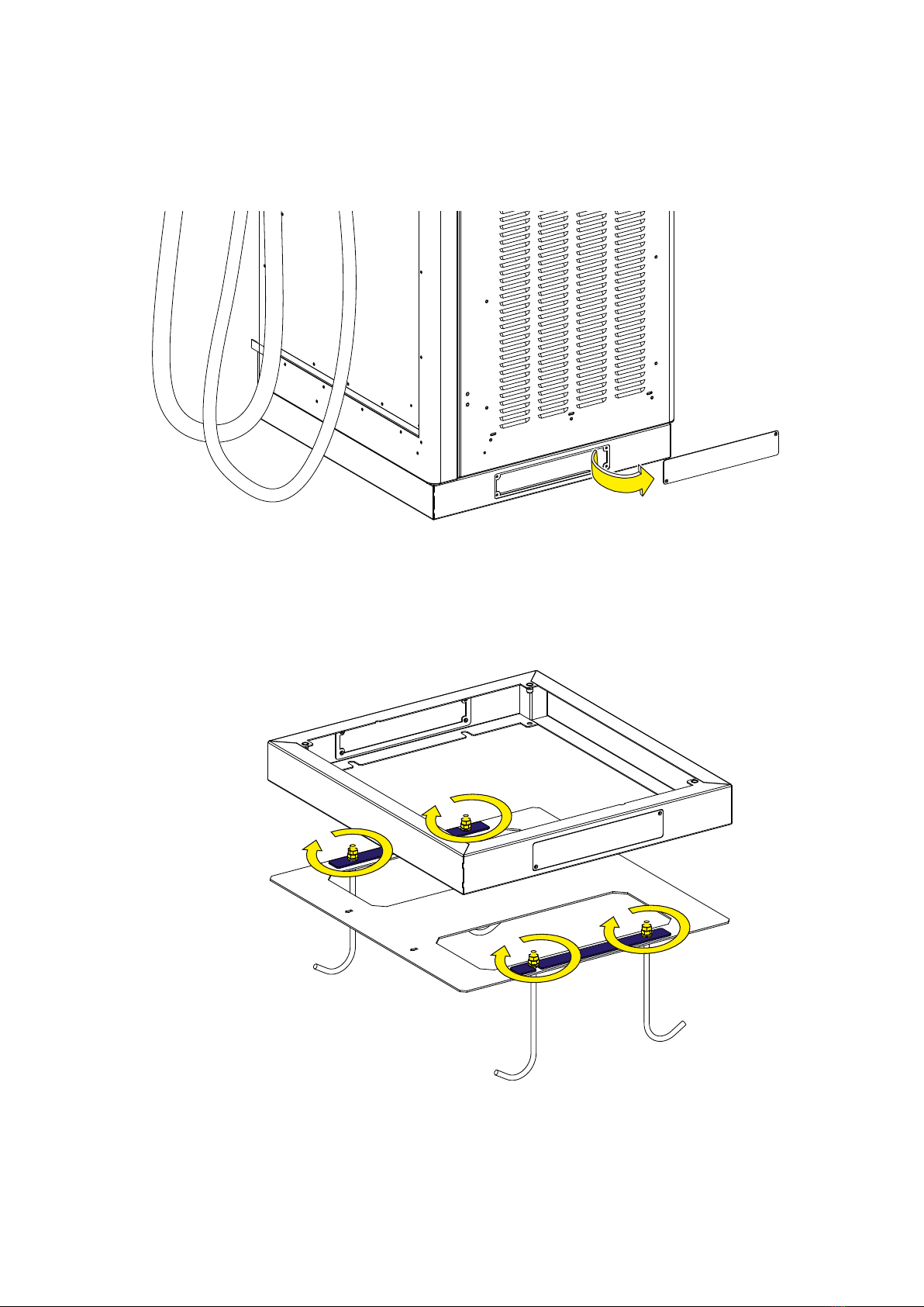
3.7 Station fixing
1.Remove the cover plates on both sides under the access doors.
2.Remove the hexagonal sleeves, or M12 nuts, depending on the type of installation, place the fixing
plates (in blue in the picture), then screw them back to anchor the station to the ground.
20
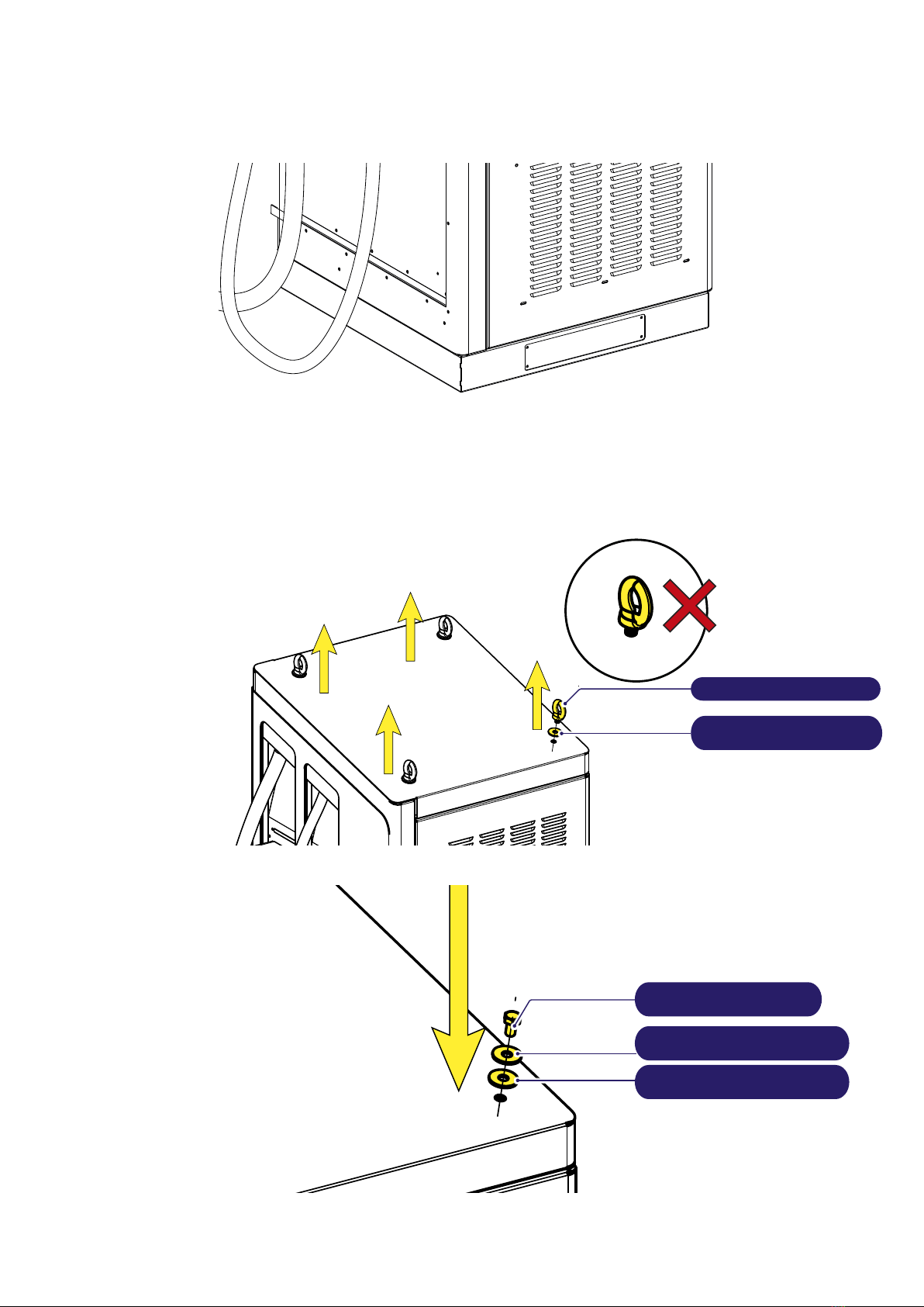
3.Mounting the cover plates.
4.
Once the station is installed in its final position, remove the eyebolts and replace them with the
supplied M12x20 screws, as shown in the figures below.
TPR Washer 37x13
thk 3 mm (DIN 125)
Eyebolt M12x20 (DIN 580)
TPR Washer 37x13
thk 3 mm (STANDARD DIN 125)
Stainless Steel Washer
37x13 thk 3 mm (DIN 9021)
Stainless Steel Screw
M12x20 (DIN 933)
This manual suits for next models
3
Table of contents
Other Fimer Automobile Batteries Charger manuals


