CTEK D250T User manual

USER MANUAL
CTEK DC/DC BATTERY CHARGER D250T
AND 24V POWER MANAGEMENT SYSTEM SMARTPASS 120T
2 YEAR
WARRANTY
ENDEFRESITNLSVDANOFIPLJAKOZH

•3
EN
MANUAL
CONGRATULATIONS
on the purchase of your new CTEK charger providing professional battery care. This charger is
included in a series of professional chargers from CTEK SWEDEN AB and represents the latest
technology in battery charging. With the CTEK D250T and SMARTPASS 120T you will maximize the
performance from your dual battery system.
SAFETY
CALIFORNIA PROPOSITION 65
WARNING: This product contains chemical known to the state
of California to cause cancer or reproductive toxicity.
• The D250T and SMARTPASS 120T have been developed for 24V lead-acid batteries. Do not use
either of these units for any other type of battery.
• Wear protective goggles when connecting and disconnecting batteries.
• Battery acid is corrosive. Rinse with plenty of water immediately if you get acid on your skin or in your
eyes. Get medical assistance.
• Never use a charger with damaged electric cables. Check that the cables have not been damaged by
hot surfaces, sharp edges or in any other way.
• Explosive gases are generated while lead-acid batteries are being charged. Avoid any sparking near
the battery. Install the devices in a well-ventilated area to ensure that the unit will not be overheated.
• Never place the charger above the battery, and do not cover the charger during charging.
• Disconnect the battery terminal posts before installing.
• The D250T and SMARTPASS 120T are not spark-free.
• The installation must include a fuse in accordance with the recommendations in the table
”CABLE AND FUSE REQUIREMENTS” contained within this manual.
Remember that all installations in boats must comply with ISO 10133!
1. The cabling from the batteries must have fuses near the batteries.
2. The batteries must be securely fastened in a ventilated space.
3. The cabling must be run through pipe ducting, separately from 230V/110V wiring (mains power),
or secured by clips at every 30 cm/1 ft.
4. Cabling in the engine compartment must be temperature rated at 70C/ 158F.
Temperature sensor
Connector plate
D250T
SMARTPASS 120T
Temperature sensor
+IN Input Alternator +OUT Output Service battery
Earth Connection Start Battery Midpoint
+OUT Output Non-critical Consumers
Smart alternator cable (red)
Negative cable connection (black)
WARNING!
The D250T and SMARTPASS120T
are not protected against reversed
polarity. Disconnect the battery
terminal posts before installation.
WARNING!
The D250T and SMARTPASS120T
are not spark-free.
Ensure good ventilation.
Output status signal

4•
FUNCTIONS
• General
D250T is a 24V DC-DC battery charger for a dual battery system with a starter battery and
a service battery. D250T is designed to be used as an onboard charger, for charging and
maintaining a 24-volt service battery from the vehicle alternator when motor is running.
• Charging
D250T uses a 4-step automatic charging algorithm to charge the service battery with up to 10A
when a conventional alternator (constant voltage) is running.
• Starter battery under voltage protection
The charging process is automatically switched off when the engine is not running to prevent
discharge of the starter battery.
• Temperature compensation
The external temperature sensor will adjust the charge voltage according to actual temperature
of the service battery. The charge voltage is reduced at higher temperatures and is increased at
lower temperatures. The temperature sensor should if possible be attached to the Service Battery,
or as close to it as possible. (see figure 4)
• Battery separation
D250T separates the starter battery from the service battery when the engine is not running. The
battery separation protects the starter battery from being discharged, this eliminates the needs for
diodes and VSR relays.
• Service battery temperature protection
The external temperature sensor attached to the service battery is protecting the service battery
from high temperatures by switching off the charging process if the measured temperature rises
too high. The charger will automatically restart when the service battery temperature reduces to a
level level within the specified operating temperature.
• Equalizing the starter battery
In a 24V system, where we have two 12V batteries in series, the voltage in the two batteries can
be unbalanced, especially if there are 12V consumers connected to one of the batteries. When
the service battery is fully charged, the D250T will measure the voltage levels in both 12V starter
batteries. If there is a difference between the voltage in these two batteries, the D250T is will
equalize the voltage levels to increase battery performance and lifetime.
• Protects service battery from overcharging
D250T will not overcharge the service battery. When the service battery is fully charged D250T
will go into pulse charging mode to monitor and maintain the charge status battery. If battery
voltage drops too low the charging process will restart.
• SMARTPASS 120T
Fully compatible with SMARTPASS 120T to provide the ultimate power management solution for
dual battery systems.
• Remote status indicator lamp
There are no LED indicator lamps on the units themselves but there is a status signal lead attached
to the charger. This can be connected to a 24V lamp (Max. 2W) for remote indication of charger
status, in the driver’s cab or other places where indication is needed.
D250T D250T

•5
EN
FUNCTIONS
• General
SMARTPASS 120T is a Power Management Solution which distributes, controls and maximizes
available energy from the vehicle alternator to service batteries and other consumers.
SMARTPASS 120T connects the service battery to the alternator/starter battery in order to split
charge and deliver up to 120A continuously to the service battery and parallel consumers.
• Split charging
SMARTPASS 120T connects the service battery to the starter battery when the alternator is
running, or when the starter battery voltage is kept above a set threshold by another power
source, for example an external battery charger.
• Battery separation
SMARTPASS 120T separates the starter battery from the service battery when the engine is not
running. The battery separation protects the starter battery from being discharged, this eliminates
the needs for diodes and VSR relays
• Service Battery guard (Deep discharge protection)
Turns off all the equipment connected to the SMARTPASS 120T consumer output when service
battery voltage is low, this protects the service battery from deep discharge and will extend
battery life. The consumer output will reconnect when service battery voltage has increased back
to a level within specified operating range.
• Critical consumers
If there are some consumers with low power consumption that must be prioritized (critical
consumers), they can be connected directly to battery. This will ensure they are always connected
to the service battery. Please note: by connecting consumers directly to the service battery, the
SMARTPASS 120T can no longer protect against deep discharge.
• Assigning current source priority
When the alternator is running, the SMARTPASS 120T will supply consumers with current directly
from the starter battery (alternator). This feature will maximize the charging efficiency when a
D250T is used in the system as no consumers will take any power from service battery.
• Dynamic overcurrent protection
SMARTPASS 120T can handle temporary inputs and outputs of up to 350A for fast charging. It
has an overcurrent protection and internal temperature monitoring to protect electronic circuits and
keep the electronics within safe operation.
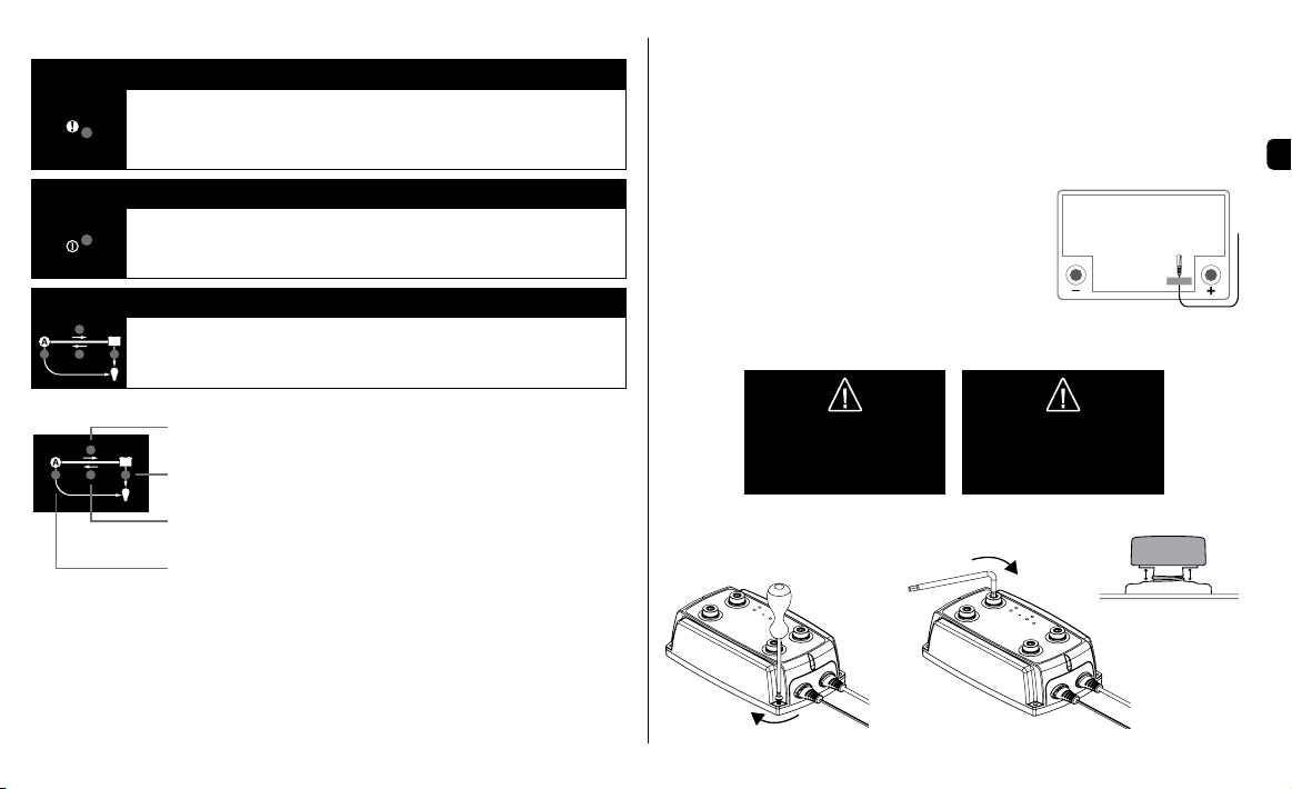
• Smart Alternator
SMARTPASS 120T can also be used when vehicle is equipped with a smart alternator (with
variable charging voltage). This is activated by connecting the red smart alternator cable
according to the instruction in this manual.
• Overvoltage protection
The Alternator input is electronically overvoltage protected. If voltage from alternator is too high
SMARTPASS 120T will turn off the connection to service battery and consumers.
• Service battery temperature protection
SMARTPASS 120T is equipped with a temperature sensor to be attached to the service battery
pack. This protects the battery by switching off the connection between starter battery and service
battery if the service battery temperature is too high, i.e. not allowing charge from the alternator to
the service battery.
• Starter battery trickle charging
When the service battery voltage is higher than the starter battery, the SMARTPASS 120T will
trickle charges the starter battery by periodically connecting the service battery output to the
alternator input. This can be helpful to compensate for the self-discharge of the starter battery. It
is especially useful if another power source is feeding the service battery, for example a battery
charger.
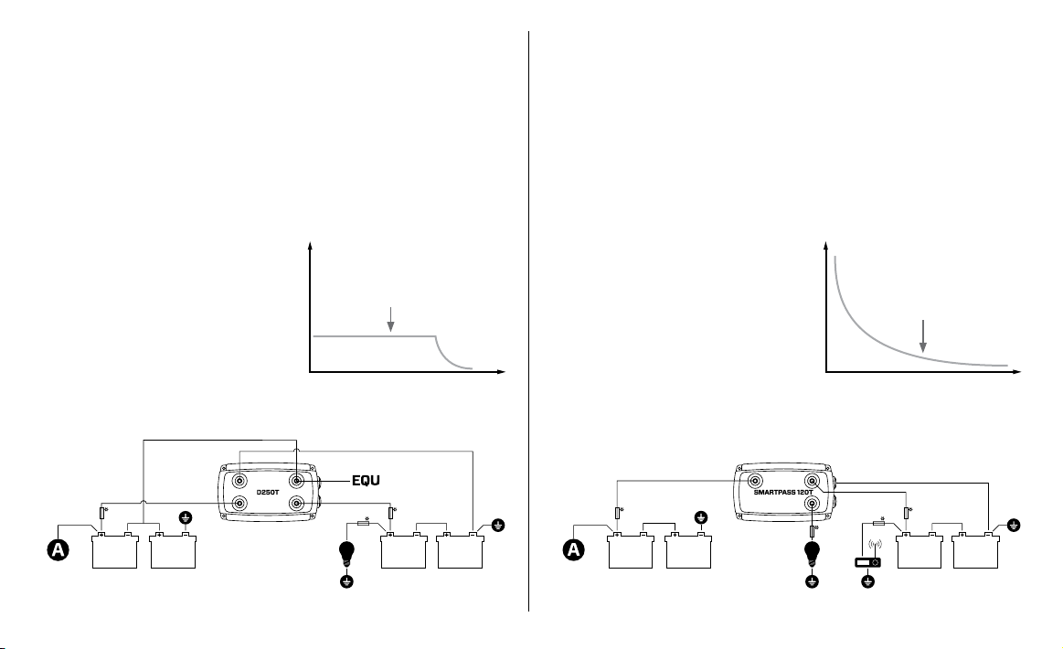
• Compatible with D250T
To get the optimal dual battery management system the SMARTPASS 120T should be combined
with D250T DC-DC charger to get a stable, reliable and optimized charging system. D250T and
SMARTPASS 120T can together charge the service battery and provide the consumers up to
130A of power.
• Overvoltage protection
Alternator input is electronically overvoltage protected. If voltage from the alternator is too high
the SMARTPASS 120T will disconnect the connection to the service battery and consumers.
When voltage is back within the normal range SMARTPASS 120T will automatically open the
connections.
SMARTPASS 120T SMARTPASS 120T

6•
FUNCTION INDICATIONS - D250T
There are no LED indicator lamps on the units themselves but there is a status signal lead attached
to the charger. This can be connected to a 24V lamp (Max. 2W) for remote indication of charger
status, in the driver’s cabinet or other places where indication is needed.
Signal Description
Not enough input voltage to charger. System is shut off, no charging is in
progress.
The system is ON and is working properly.
Major fault.
CABLE AND FUSE REQUIREMENTS
UNIT CABLE
MIN. CABLE SIZE
FUSE
0.5 m
2 ft
1 m
3 ft.
2 m
6 ft.
5 m
15 ft.
10 m
30 ft.
D250T
+IN +IN
2.5 mm2/
AWG14
2.5 mm2/
AWG14
4 mm2/
AWG12
4 mm2/
AWG12
6 mm2/
AWG10 15A
+OUT +OUT
2.5 mm2/
AWG14
4 mm2/
AWG12
6 mm2/
AWG10 15A
EQU 2.5 mm2/
AWG12
2.5 mm2/
AWG12
4 mm2/
AWG12
4 mm2/
AWG12
6 mm2/
AWG12 15A
+SIGNAL 1.5 mm2/
AWG16
1.5 mm2/
AWG16
1.5 mm2/
AWG16
1.5 mm2/
AWG16
1.5 mm2/
AWG16
-EARTH 1.5 mm2/
AWG16
1.5 mm2/
AWG16
1.5 mm2/
AWG16
1.5 mm2/
AWG16
1.5 mm2/
AWG16
Connector plate* 2.5 mm2/
AWG14
4 mm2/
AWG12
6 mm2/
AWG10
SMARTPASS
120T
+IN +IN
35 mm2
AWG2
35 mm2
AWG2
35 mm2
AWG2
50 mm2
AWG1
50 mm2
AWG1 300A
+OUT +OUT +OUT
35 mm2
AWG2
35 mm2
AWG2
35 mm2
AWG2 300A
*If the D250T and SMARTPASS 120T are installed in different locations and the accompanying connector plate is
not used, please follow the recommendations in the table.

•7
EN
REQUIRED TIGHTENING TORQUES
Figure 1 Figure 2
Figure 5
INSTALLATION
The installation should be done by a person with knowledge of automotive installations.
1. The D250T & SMARTPASS 120T unit(s) should not be directly exposed to fuel, oil or dirt. They
should be installed on a flat surface to ensure they can be firmly secured. If you are fitting both units
together attach the accompanying connector plate (see Figure 3) before fitting them into the vehicle.
2. Secure the unit(s) with M4 or ST4.2 screws at each corner (see Figure 1).
3. Before connecting the cables, ensure that the negative terminal post on both the starter and service
battery is not connected.
4. Connect the cables to the unit connections by securing the M8
screws with the required tightening torque. (see Figure 2).
Use an Allen key - tightening by hand without a tool is not
enough. The cables connected to M8 terminals must be
equipped with ring terminals. Max thickness of connected ring
terminal(s) is 6mm (see figure 5).
5. Use tape (see Figure 4) to secure the temperature sensor
to a clean flat surface above the service battery. Position the
sensor as close to the positive terminal post as
possible.
6. Connect the battery negative terminal post.
8 Nm/71 lb-in
2 Nm/18 lb-in
Allen key
Figure 4
Max 6 mm
Max 6 mm
WARNING!
The D250T and SMARTPASS120T
are not protected against reversed
polarity. Disconnect the battery
terminal posts before installation.
WARNING!
The D250T and SMARTPASS120T
are not spark-free.
Ensure good ventilation.
FUNCTION INDICATIONS - SMARTPASS 120T
Error lamp
OFF: No errors detected.
ON: Error detected.
In combination with flashing LED you will get more information about the
error. See also section “Error indication”.
Power lamp
OFF: Incoming voltage too low, no power to device.
ON: Power on.
Connection gates
OFF: Gate is closed and no current is passing through.
ON: Gate is open and current is passing through.
FLASHING*: Gate error due to high current or high temperature.
Alternator to service battery.
Service battery to non-critical consumers.
*Flashing light here also indicates low voltage in service battery.
Service battery to starter battery.
Alternator to non-critical consumer.

8•
DIMENSIONS
65mm / 2.53 inches
240mm / 9.44inches
250mm / 9.84inches
90mm/3.57 inches
120mm/4.72 inches
210mm/8.29 inches
Ø4,9 mm
0.19 inches
168mm/6⅝ inches
Figure 3
Ignition signal, +15 clamp
(DIN 72552)
Temperature sensor
Smart alternator cable (red)
Chassis/Earth
SETTINGS SMARTPASS 120T
Smart alternator cable (red) Type of alternator
Not connected Conventional alternator
Connected Smart alternator
Negative cable connection (black)

•9
EN
SYMBOLS AND TERMINALS
Fuse See ”CABLE AND FUSE REQUIREMENTS”
Flashing lamp Continuously lit lamp
Alternator Non critical consumer
Earth connection Critical consumer
Connection D250T Connected to
Equalization EQU Mid point of starter battery
Input Alternator +IN
• Starter battery
• Input Alternator SMARTPASS 120T via
connector plate or cable
Output Service battery +OUT
• Service battery
• Output Service battery SMARTPASS 120T
Earth Connection
• Chassis/Earth
• Solar panel (-)
• SMARTPASS 120T (-)
Connection SMARTPASS 120T Connected to
Input Alternator +IN
• Starter battery
• Input Alternator D250T via connector plate
or cable
Output Service battery +OUT Output Service battery D250T
Output Consumers +OUT Non-critical consumers
Smart generator (red cable) See "SETTINGS SMARTPASS 120T"
DEFINITIONS AND DESCRIPTIONS
STARTER BATTERY
A battery intended for the engine’s electric starter motor in automotive applications.
A starter battery should never be deeply discharged.
SERVICE BATTERY
Service battery is an auxiliary battery that will provide power to electrical equipment when the
vehicle motor is not running. This additional battery will prevent the starter battery to be being
drained and protect against a flat battery. Suitable deep cycle batteries should be used.
TEMPERATURE SENSOR
The D250T optimises the charge voltage by increasing the charge voltage at temperatures below
25°C/77°F and reducing it at temperatures higher than 25°C/77°F.
TEMPERATURE COMPENSATED CHARGE VOLTAGE
The charger will adjust the charge voltage according to service battery temperature. This can be
done by attaching the temperature sensor to the starter battery or somewhere close to the battery.
BATTERY TEMPERATURE PROTECTION
Protects the battery by switching off charging if the temperature rises too high.
FUSES
Fuses must be used for overload protection. Mount the fuses as close to each battery as
possible. Please see this instruction manual for recommended fuse sizes - see “CABLE AND FUSE
REQUIREMENTS” table.
WIRING
Please see this instruction manual for recommended cable length and sizes - see “CABLE AND FUSE
REQUIREMENTS” table.
CONSUMERS
Consumers should normally be connected to the consumer output terminal on the SMARTPASS 120T.
If battery voltage reaches a critically low level, the consumer output terminal is deactivated to protect
the service battery from being deeply discharged.
When the vehicle motor is running, non-critical consumers receive current from the alternator instead
of the service battery, for faster charging of the service battery.
If there are some consumers with low power consumption that must be prioritized (critical consu-
mers), they can be connected directly to battery. This will ensure they are always is connected to the
service battery. Please note: by connecting consumers directly to the service battery, the SMARTPASS
120T can no longer protect against deep discharge. A critical consumer could be a ticket system, life
support equipment, communication radio etc.
EQUALIZING (EQU)
In a 24V system where we have two 12V batteries in series the voltage in the two batteries can be
unbalanced, especially if there are 12V consumers connected to one of the batteries. The Equalizing
process is balancing the voltage level in the two batteries and ensures battery performance and
extends battery life.

10•
INSTALLATION EXAMPLES
PREREQUISITES
A dual battery system, where the D250T
charges a service battery from the vehicle
alternator when the motor is running.
Use this installation when the priority is to charge
and maintain the service battery with the opti-
mum charge voltage, and when there are no, or
minor, parallel consumers that need power when
the vehicle is running. Parallel loads will reduce
available charge current and extend charging
times. If you are charging parallel consumers,
we recommend you also install a SMARTPASS
120T. See installation example #3.
Use this installation when:
– Priority to charge the service battery with
optimum voltage.
– No or minor parallel consumers
to Service battery.
– Service battery capacity up to approx.
150Ah, for larger batteries the charging time
will be too long.
1. Small service battery
PREREQUISITES
SMARTPASS 120T connects the service battery
with the alternator/starter battery in order to split
charge and supply up to 120A continuously to
the service battery and parallel consumers.
Use this installation when the priority is to
manage larger consumers parallel to the service
battery that require power when the vehicle is
running.
One basic condition required for this installation
is that the alternator can deliver sufficient voltage
to supply equipment and split charge the service
battery. If the alternator is not able to provide
enough voltage to fully charge the battery, the
SMARTPASS 120T will not either. In this case,
we recommend that you also install the D250T
DC/DC charger.
Connect the cabling from the starter and service
batteries respectively to the SMARTPASS 120T
and not to the D250T.
Use this installation when:
– Large electrical consumers parallel
to service battery.
– Alternator able to provide the desired voltage
– Power management is priority.
– Larger service battery capacity up to 800 Ah.
2. Service battery with parallel consumers
*See ”CABLE AND FUSE REQUIREMENTS” *See ”CABLE AND FUSE REQUIREMENTS”
STARTER
BATTERY
STARTER
BATTERY
SERVICE
BATTERY
SERVICE
BATTERY
STARTER
BATTERY
STARTER
BATTERY
SERVICE
BATTERY
SERVICE
BATTERY
I
t
I
t
D250T charges service battery with
10A until the battery reaches max
voltage. The current then tapers off
to a fully charged battery.
Power is forwarded directly from
alternator to the service battery.
High current initially (up to
30minutes) Current tapers off to
very low level 100% charge from
alternator is not possible to reach.
Max. 100A

•11
EN
PREREQUISITES
A dual battery system where the D250T,
together with SMARTPASS 120T, will charge
the service battery when the vehicle motor is
running. and It will also manage available
power from the alternator to both the service
battery and parallel consumers.
This installation will give a system that both can
manage large parallel loads and at the same
time charge maintain the service battery, with
the optimum voltage for a 24V dual battery
system. The battery charging will be more
efficient and shorter as we are getting access to
a higher current initially, parallel consumers will
be powered directly from alternator.
Use this installation when:
– Large electrical consumers parallel to service
battery need power when the motor is
running.
– Need onboard charging and maintenance of
the service battery.
– Large service battery capacity (up to 800 Ah).
– A safe and reliable onboard charging and
power management system is required.
An AC/DC battery charger can be connected to
the service battery as complement to D250T and
SMARTPASS 120T. This can be useful if:
• Power from the alternator, when the engine
is running, is not enough to fully charge the
service battery. Additional charge is needed
to fill the battery up to 100%.
• Maintenance charging of the service battery
(and starter battery) during long time storage
of vehicle. The AC/DC charger will ensure
that the batteries are fully charged when the
vehicle should be used again.
• You will have access to AC power at your
destination. The AC/DC charger will charge
the battery and act as power supply for
connected consumers.
• Select the size of AC/DC battery charger
suitable for the size of the battery and all
consumers that are active whilst charging. For
example: A 10A charger will not charge a
battery at all if you have a 10A light turned
on.
Tips: If the starter battery needs charging, it
is possible to connect the AC/DC charger
to the starter battery and the D250T and
SMARTPASS120T will charge and maintain to
the service battery in at the same time.
3. Large service battery with parallel consumers 4. Connect an AC/DC charger
*See ”CABLE AND FUSE REQUIREMENTS” *See ”CABLE AND FUSE REQUIREMENTS”
STARTER
BATTERY
STARTER
BATTERY
SERVICE
BATTERY
SERVICE
BATTERY STARTER
BATTERY
STARTER
BATTERY
SERVICE
BATTERY
SERVICE
BATTERY
Initially high current directly from
alternator, when current drops to
10A D250T will continue charging
according to charge algorithm.
I
t
Max. 100A Max. 100A

12•
CHARGING PROGRAM D250T
The D250T will charge the service battery in 4 steps - Bulk, Absorption, Float and Pulse. The last step,
Pulse maintenance, means that the D250T monitors state of charge of the service battery, keeping
the battery fully charged without risk of overcharging. During this step, the D250T will also monitor
state of charger of the starter battery set, sending out voltage to each battery separately to equalize
the two 12V batteries – this will significantly extend battery life. Equalization ends when the service
battery needs charging or when the two batteries in the starter battery set have the same voltage.
STEP 1 BULK
Charging with maximum current until approximately 80% battery capacity.
STEP 2 ABSORPTION
Charging with declining current to maximize up to 100% battery capacity.
STEP 3 FLOAT
Maintaining the battery voltage at maximum level by providing a constant voltage charge.
STEP 4 PULSE
Maintaining the battery at 95–100% capacity. The charger monitors the battery voltage and
gives a pulse when necessary to keep the battery fully charged.
4321
PULSEFLOAT
ABSORPTIONBULK
VOLTAGE (V)CURRENT (A)
SMARTPASS 120T FAULT INDICATIONS
Each LED indicator lamp works individually and a flashing light is indicating an error according to
description below.
Note that several combinations can be possible if there is more than one errors. For further details
please refer to the manual - see “FUNCTION INDICATIONS” table.
SMARTPASS 120
+OUT
+OUT
+IN
Reason: Internal temperature too high and/or current too high in
connection between alternator/starter battery and service battery.
Note that both lamps will flash to even if an error only occurs from
one direction.
Recommendation: Check service/starter battery with a battery
tester, the service/starter battery may be too deeply discharged
and need reconditioning or replacing. This error can also occur if
the loads are too big and it can help to reduce the use of electric
consumers.
Reason: Internal temperature too high and/or current too high in
connection from service battery to non-critical consumer. This lamp
will also indicate if battery voltage is too low and the battery guard
is activated, this will disconnect power to the non-critical consumers.
Recommendation: Reduce the use of electrical consumers,
consider moving the D250T and/or SMARTPASS 120T to a cooler
location with better ventilation or charge the battery.
Reason: Internal temperature too high and/or current too high in
the connection from alternator to non-critical consumer.
Recommendation: Reduce the use of electrical consumers and
consider moving the D250T and/or SMARTPASS 120T to a cooler
location with better ventilation.
The indication combination below is indicating overheating error
SMARTPASS 120
+OUT
+OUT
+IN
Reason: Service battery is overheating.
Recommendation: Check the service battery with a battery
tester and/or check the installation.

•13
EN
TECHNICAL SPECIFICATION
PRODUCT D250T SMARTPASS 120T
Model number 1048 2003
Input 25. 6–32V, 10–15A 22.8–32V
Output battery 28.8V at +25°C, Max. 10A Max. 120A continuously. Intermittent up to 350A.
Output consumer Max. 100A***
Back current drain Less than 1Ah/month Less than 9Ah/month
Ripple* Less than 4% Not applicable
Ambient temperature -20°C to +50°C (-4°F to +122°F)
Temperature-compensated charging voltage 28.8V at +25°C, voltage reduced at higher temperatures
and is increased at lower.
Battery types All types of lead-acid batteries (WET, MF, Ca/Ca, AGM, GEL)
Recommended battery capacity 28–150Ah 28–800Ah
Dimensions/Weight 192 x 110 x 65mm (L x W x H) / 0.7 kg (1.5 lbs)
Enclosure class IP65 (splash and dust proof)
MPPT** No No
Conventional alternator cut-in >26.2V, for 5 sec. (engine running, alternator charging) >26.2V, for 4 sec. (engine running, alternator charging)
Conventional alternator cut-out <25.6V, for 5 sec. (engine running, alternator not charging) <25.5V, for 4 sec. (engine running, alternator not charging)
Smart alternator cut-in Not applicable >23.6V, for 4 sec. (engine running, alternator charging)
Smart alternator cut-out Not applicable <22.8V, for 4 sec. (engine running, alternator not charging)
Battery guard cut-in (Service battery) <23.0V (5s)
Battery guard cut-out (Service battery) >24.0V (5s)
Temperature protection cut-in >70°C (158°F) >60°C (140°F)
Trickle charge starter battery Starter battery 18V–25.2V.
*) The quality of the charge voltage and charge current is very important. A high current ripple heats up the battery which has an aging effect on the positive electrode. High voltage ripple could harm other
equipment that is connected to the battery. CTEK battery chargers produce very clean voltage and current with low ripple.
**) MPPT (Maximum Power Point Tracker) finds the best combination of current and voltage so that the output power is maximised.
***)Total max output current for Smarttpass is 120A and available current from alternator will be distributed into the two different output channels, Output Battery and Output Consumer. Specified values is
the maximum current for each output.

14•
LIMITED WARRANTY
CTEK issues this limited warranty to the original purchaser of this product. This limited warranty is
not transferable. The warranty applies to manufacturing faults and material defects. The customer
must return the product together with the receipt of purchase to the point of purchase. This
warranty is void if the product has been opened, handled carelessly or repaired by anyone other
than CTEK or its authorised representatives. One of the screw holes in the bottom of the product
may be sealed. Removing or damaging the seal will void the warranty. CTEK makes no warranty
other than this limited warranty and is not liable for any other costs other than those mentioned
above, i.e. no consequential damages. Moreover, CTEK is not obligated to any warranty other
than this warranty.
SUPPORT
Visit: www.ctek.com for support, FAQ, the most recent version of the user instructions and further
information concerning CTEK products.
50023485A
This manual suits for next models
1
Table of contents
Other CTEK Automobile Batteries Charger manuals
Popular Automobile Batteries Charger manuals by other brands

Mannesmann
Mannesmann Jump Start/Air Compressor instruction manual

SyncEV BG
SyncEV BG EVS7G Installation and user guide

ABL
ABL eMH1 WALLBOX instruction manual

CRAIG & DERRICOTT
CRAIG & DERRICOTT SMART ION CHARGE EV03221000 Installation & maintenance

Power Electronics
Power Electronics Standalone NB 120 installation manual

BEAMA
BEAMA Electric Vehicle Infrastructure Guide to installation and use