Fimer FLEXA User manual

Installation manual
FIMER FLEXA AC Wallbox

SAFETY INSTRUCTIONS
ATTENTION –AThis manual contains important safety instructions that must be followed
during installation and maintenance of the equipment.
KEEP THIS MANUAL
READ THE MANUAL –EKeep this document in a safe place for easy access at all times
during installation and maintenance.
THE INSTALLER MUST READ THIS DOCUMENT IN ITS ENTIRETY BEFORE INSTALLING THE
EQUIPMENT
READ THE MANUAL –EOperators are required to read this manual and to comply strictly
with the instructions it contains.
FIMER cannot be held responsible for damage caused to persons and/or property, or to the equipment,
if the conditions described below have not been complied with.
The purpose of this document is to support qualified technicians, who have received appropriate
training and/or have demonstrated adequate skills and knowledge in the construction, installation,
operation and maintenance of electrical equipment.
The warranty requirements are contained in the Terms and Conditions of Sale section included with
the purchase order for this product.
NOTE –DAny modification not approved by FIMER will immediately invalidate the
product warranty.
WARRANTY AND DELIVERY CONDITIONS
The warranty conditions are considered valid if the customer complies with the instructions contained
in this manual; any deviation from the warranty conditions with respect to what is described below
must be expressly indicated in the purchase order.
FIMER declares that the equipment complies with the legal provisions currently in force in the country
of installation and has issued the relative declaration of conformity.
FIMER assumes no responsibility for failure to comply with the instructions for proper installation and
cannot be held responsible for the systems upstream or downstream of the equipment supplied.
It is absolutely forbidden to modify the equipment. Any modification, manipulation or alteration of the
hardware or software not expressly agreed with the manufacturer will immediately void the warranty.
Due to the large number of possible combinations of system configurations and installation
environments, it is essential to check the following before installing the product: adequate space for
housing the equipment, ambient noise produced by the environment and possible flammable
conditions.
FIMER cannot be held responsible for defects or malfunctions deriving from: improper use of the
equipment; deterioration due to transport or particular environmental conditions; incorrect or
insufficient maintenance; tampering or unsafe repairs; use or installation by unqualified persons.
FIMER is not responsible for any disposal of the equipment, or part of it, that does not comply with
the regulations and laws in force in the country of installation.

PURPOSE AND STRUCTURE OF THE DOCUMENT
This user and maintenance manual is a guide to help you to work safely and carry out the necessary
operations to keep your equipment in good working order.
If the equipment is used in a manner not specified in this manual, the protection provided by the
equipment may be impaired.
This document was originally written in Italian. Therefore, in case of inconsistencies or doubts, ask
FIMER for the original document.
LIST OF DOCUMENTS IN THE APPENDIX
READ THE MANUAL –EIn addition to this user manual, product documentation can be
consulted and downloaded by visiting www.fimer.com.
READ THE MANUAL –EThis document only contains the information deemed necessary
for the use and routine maintenance of the equipment.
SKILLS AND REQUIREMENTS OF THE OPERATOR AND MAINTENANCE PERSONNEL
READ THE MANUAL –EPersonnel involved in the use, maintenance and installation of the
equipment must be qualified by FIMER (by means of a letter certifying their qualification)
for the activities described and must reliably demonstrate their ability to correctly interpret
what is described in the manual.
ATTENTION –AThe installation must be carried out by FIMER-qualified installers and/or
FIMER-authorised electricians in accordance with the regulations in force in the country
of installation and in compliance with all safety regulations for carrying out electrical work.
FORBIDDEN –HIt is forbidden to entrust the installation or maintenance of the product to
unqualified persons or those in an altered physical or mental state.
ATTENTION –AThe customer bears civil responsibility for the qualification and mental or
physical state of the personnel who handle the equipment. Such personnel must always use
the personal protective equipment (PPE) required by the laws of the country of destination
and by the instructions of their employer.

Table of content
1. General information
1.1 .......................................................................................................Fields of use 7
1.2...................................................................................Symbols and definitions 8
1.3....................................................................Product dimensions and features 10
1.4........................................................................ Available models and versions 11
1.4.1 ................................................................... Features of Stand Alone model 11
1.4.2.................................................................... Features of Inverter Net model 11
1.4.3 ...................................................................... Features of Future Net model 11
1.4.4............................................................................ Master/Slave functionality 12
1.5...............................................................................................................Support 12
1.6....................................................................................................Technical data 13
2. Safety and equipment
2.1 .................................................................................................Safety warnings 14
2.2 .........................................................................................................Proper use 14
2.3............................................................................................... Product handling 15
3. Installation
3.1 ..................................................................................Preparing for installation 16
3.2....................................................................................................Tools required 17
3.3.............................................................................................. Package contents 17
3.4...................................................................................... Space and positioning 18
3.5.......................................................................................................... Unpacking 19
3.6...................................................................... Wall mounting plate installation 20
3.7........................................................................FLEXA AC Wallbox installation 21
3.8........................................................... Connection of power and earth cables 22
3.9............................................................Residual-Current device management 26
3.10 ...............................................................Communication cables connection 28
3.11 ...............................................................................................Port description 29
3.11.1 ....................................................................................... AC Relé OUT-J31 30
3.11. 2 ..........................................................................................CT Sensor – J4 30
3.11.3 .........................................................................................Gigabit Ethernet 31
3.11.4 .............................................................................. RS-485 Smart Grid-J5 31
3.11.5 ................................................................................ RS-485 Mid Meter-J6 34

3.12 .........................................................................Dynamic Power Management 35
3.12.1 ................................................................................ CT sensor installation 35
3.12.2 ..........................................................................External meter installation 36
3.12.3 ....................... FLEXA AC Wallbox Inverter Net and REACT 2 integration 38
3.12.4 ................................... FLEXA AC Wallbox integration with solar inverters 40
3.13 .......................................................... Closing operations and power supply 41
4. First start-up and configuration
4.1 ..................................................................................................... LED behavior 42
4.2 .......................................................................LED behavior during operation 43
5. Operating instructions
5.1 ..................................................................... Preliminary charging operations 44
5.2......................................................................................... Charging operations 45
5. 2.1 ................................................................................................Open access 46
5.2.2 ................................................................................Remote authentication 46
5.2.3 ..................................................................................................Local RFID 47
5.2.4 ................................................................ Authentication via service center 47
5.3........................................................................................ RFID card operations 48
5.4....................................................................................... MyFIMERwallbox App 49
5.4.1 ..........................................................................FLEXA AC Wallbox pairing 49
5.4.2............................................View, add and delete your FLEXA AC Wallbox 49
5.4.3........................................................................................Firmware upgrade 50
5.4.4.............................................................................................DPM activation 50
5.4.5.......................................................................................... User limit setting 50
5.4.6.......................................................................................... Charging modes 51
5.4.7................................................................................................Consumption 51
5.4.8...................................... Monitoring consumption in multi-user applications 51
5.4.9............................................................................................... Active alarms 52
6. Troubleshooting
6.1 ........................................................................................ Alarms and warnings 53
6.1.1 .............................................................................................. Global alarms 54
6.1. 2 ...........................................................................................Global warnings 54
6.1.3 .............................................................................................. Socket alarms 55
6.1.4 .......................................................................................... Socket warnings 55
7. Maintenance
8. Decommissioning and disposal


1. General information
FIMER FLEXA AC Wallbox is the AC charging solution for powering electric vehicles, ideal for public,
semi-public and residential applications: it is available in single-phase or three-phase configurations
and can be equipped with a Type 2 SOCKET or a Type 2 CABLE or a Type 3A SOCKET (according
to the IEC 62196-2 standard). Other types of connectors are not supported.
Characterised by significant robustness and ease of use, this device allows you to charge an electric
vehicle up to a maximum of 22 kW (with Type T2 socket or cable) or up to 3.7 kW (with Type 3A socket).
ATTENTION –APrepare and size the entire power supply system in compliance with the
local and international standards in force according to the product version and the power
rating chosen.
READ THE MANUAL –EThis document describes how to install, configure, and maintain
the product.
A description of the features of the equipment is provided to identify its major components and specify
the technical terminology used in this manual.
This chapter contains information on models, details on equipment, features and technical data,
overall dimensions and identification of the equipment.
In some cases, it may be necessary to document the software configuration features separately by
consulting additional documentation to this manual intended for specialised FIMER-trained technicians
(e.g. sim data, etc.).
1.1 Fields of use
FIMER shall not be liable for damage of any kind resulting from incorrect or careless operations.
FORBIDDEN –HThe equipment may not be used for any purpose other than that intended in
the field of use. The equipment must not be used by inexperienced personnel, or even by expert
personnel if operations are carried out on the equipment that do not comply with this manual
and the accompanying documentation.
This equipment is a charging device for electric vehicles; the following classification (according to IEC
61851-1) identifies its characteristics:
• Power supply: permanently connected to the AC power supply grid
• Output: alternating current
• Environmental conditions: outdoor use
• A device for places with free access
• Fixed installation on wall or dedicated FIMER FLEXA Stand-Basic
• Protection against electric shock: Class I
• Charging type: Mode 3 according to the IEC 61851-1 standard
• Optional function for ventilation not supported
1
8
ATTENTION –AIn case of installation in TN-type earthing systems, there may be additional
specific local regulations regarding system safety and protection against faults that the installer
must understand and implement.
ATTENTION –AThe device can be used for the European and Australian markets, as up to date
certifications have been issued.
IT IS STRICTLY PROHIBITED TO:
FORBIDDEN –HInstall the equipment in environments subject to particular flammability
conditions or in adverse or unpermitted environmental conditions
FORBIDDEN –HUse the equipment with defective or disabled safety devices
FORBIDDEN –HUse the equipment or parts of the equipment by connecting it to other machines
or equipment, unless expressly provided for
FORBIDDEN –HModify operating parameters that are not accessible to the operator and/or
parts of the equipment to alter its performance or make changes to its insulation
FORBIDDEN –HClean the product with corrosive products that could damage parts of the
equipment or generate electrostatic charges
FORBIDDEN –HUse or install the equipment or any associated parts thereof without having
read and properly understood the contents of the operation and maintenance manual
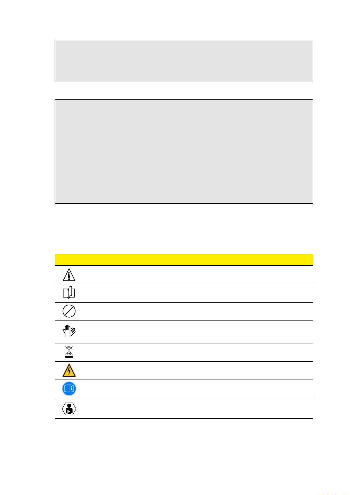
1.2 Symbols and definitions
In this manual and/or in some cases on the equipment, dangerous zones/components are indicated
by signs, labels, symbols or icons.
Symbol Description
GENERAL WARNING
IT IS MANDATORY TO CONSULT THE ORIGINAL MANUAL AND ADDITIONAL
DOCUMENTATION
PROHIBITION OR RESTRICTIONS
IT IS COMPULSORY TO PERFORM THE DESCRIBED OPERATIONS USING
THE CLOTHING AND/OR PROTECTIVE EQUIPMENT PROVIDED BY THE
EMPLOYER
ALTHOUGH THEY ARE NOT MADE OF MATERIALS THAT ARE HARMFUL TO
HEALTH, THE PRODUCTS SHOULD
SIGN FOR ELECTRICAL VOLTAGE HAZARD
SIGN FOR OBLIGATION TO READ THE INSTRUCTIONS
ELECTRONIC DEVICE INSTALLATION CARRIED OUT BY QUALIFIED
PERSONNEL ONLY

9
With respect to the symbols on the product’s nameplate, we shall identify the labeling not shown above
as follows:
44 x 130 mm
Product description
(model and version)
Product commercial code
EAN product code
Electrical characteristics
QR code for link to FIMER website
Part and Serial Number
data
Week (first 2 digits) and year
(last 2 digits) of production
Stick the QR code label in this
space
Label to removed and stuck in the
space below:
10
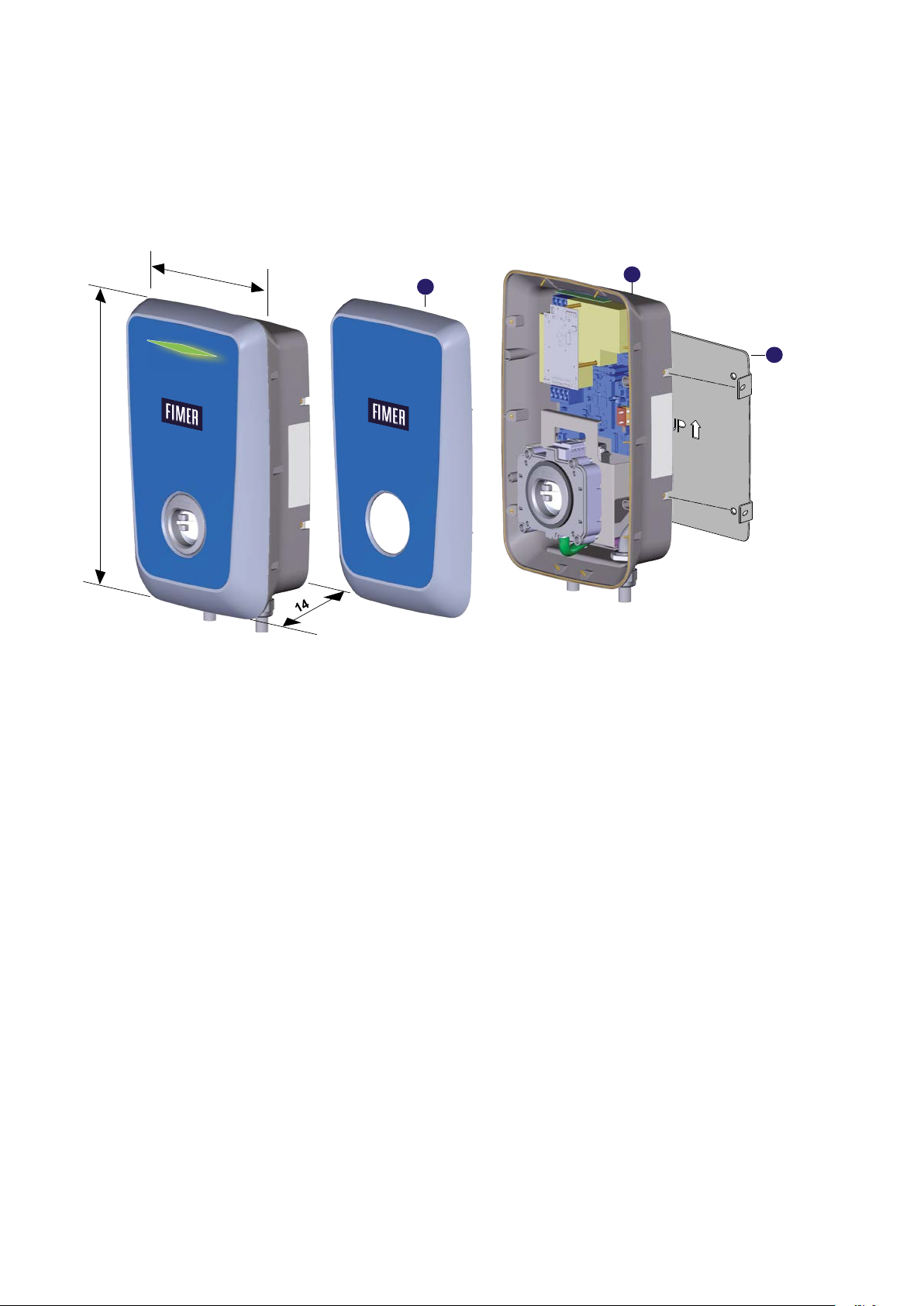
1.3 Product dimensions and features
Weight: 7 kg (socket version) and 8.5 kg (cord version)
Dimensions: 300 x 480 x 145 mm (socket version),
300 x 480 x 220 mm (cord version)
145
300
480
A
B
C
A. FRONT COVER
B. REAR CASING
C. FIXING PLATE

11
1.4 Available models and versions
The product is available in three models:
• Stand Alone
• Inverter Net
• Future Net
Each model has three available versions depending on the connection to the vehicle:
• T2C, with cable T2
• T2S, with socket T2
• T3A, with socket T3A
Four power configurations and corresponding versions are available for each model, depending on
the type of connection to the vehicle:
Power Available Sockets & Plugs
3.7 kW T3A, T2S, T2C
7.4 kW T2S, T2C
11 kW T2S, T2C
22 kW T2S, T2C
Near the socket of products supplied in T2S and T3A versions, there is a label identifying the type of
socket installed on the product.
Stand Alone,
Inverter Net and
Future Net T2S
version
AC EN 62192-2 TYPE 2 Plug
and socket ≤ 480 VRMS C
Stand Alone,
Inverter Net and
Future Net T3A
version
AC EN 62192-2 TYPE 3A Plug
and socket ≤ 480 VRMS D
1.4.1 Features of Stand Alone model
FIMER FLEXA AC Wallbox Stand Alone charges the electric vehicle in Mode 3, in ‘Open Access’
mode or via local authentication with RFID card. The device can connect to its dedicated App
(MyFIMERwallbox) via Bluetooth, allowing the user to monitor charging status and consumption,
modify operating settings, pause and restart charging, manage associated cards and check eventual
alarms. The Wallbox is equipped with a LED to identify the status of the device.
1.4.2 Features of Inverter Net model
FIMER FLEXA AC Wallbox Inverter Net maintains the same features as the Stand Alone model,
integrating communication with FIMER REACT 2 inverter via ModBus RS-485. In addition, through
the inverter management system (Aurora Vision®), both monitoring activities of operation and
parameters of the device and remote control or management activities are available. For an explanation
of these functionalities, please refer to the FIMER REACT 2 solar inverter instruction manual and
related Aurora Vision® documentation.
1.4.3 Features of Future Net model
FIMER FLEXA AC Wallbox Future Net integrates connectivity features that enable remote monitoring
and management of the device.
Unlike the other two, the Future Net model can connect to a backend via OCPP 1.6 Json protocol,
connecting with a 3G/4G SIM, Wi-Fi or via Ethernet. Authentication to start charging can take place
via the associated backends’ App and via the service center’s RFID card.

12
1.4.4 Master/Slave functionality
In applications with multiple charging points, FIMER FLEXA AC Wallbox provides Master/Slave
functionality, offering a competitive, smart and efficient solution thanks to its integrated load
management system.
The Master/Slave function allows the Future Net model to be connected with multiple Stand Alone
models, up to a total of 32 devices, via an RS-485 connection.
THE CHARGING POLICIES AVAILABLE IN THE M/S CONFIGURATION ARE:
FIFO
With this charging policy, the EVs can be charged one at a tie according to the arrival order. For 30
minutes (configurable) a complete charge cycle is provided, giving priority to the first who arrived. The
last car to arrive will go in the queue of all cars that have not yet made a first charge cycle but will
precede cars that have already made a charge cycle.
EXTENDED FIFO
Multiple EVs can be charged simultaneously. Based on the order of arrival, as many cars as possible
will be charged at maximum current. At the end of the maximum charging cycle, the cars will divide
the remaining available current equally. The limitation depends on the plant current set point.
DEMOCR ATIC FIFO
Multiple EVs can be charged at the same time. Based on the order of arrival, only one car is charged
to the maximum while the others share the remaining current. When all cars have done a maximum
charging cycle, then all will share the available residual current. The limitation depends on the plant
current set point.
FULL DEMOCRATIC
Multiple EVs can be charged at the same time. All cars will share the available current equally. The
limitation depends on the plant current set point.
These charging policies can be set through the EVI Tool.
1.5 Support
For any reports or requests for further support, FIMER is available through the dedicated section of
the website www.fimer.com or by writing to service.emobility@fimer.com.

13
1.6 Technical data
Technical data
FIMER FLEXA AC Wallbox model Stand Alone / Inverter Net / Future Net
Maximum power 3.7 kW 7.4 kW 11 kW 22 kW
Standard IEC 61851-1:2017, IEC 61851-21-2:2018
Charging method Mode 3
Available outlets 5m Cord (T2) or Socket (T2 or T3A)
Power system 1P + N + PE 1P + N + PE 3P + N + PE 3P + N + PE
Rated voltage 1)
230 VAC ± 10%
110 VAC L-G
220 VAC L-L
230 VAC ± 10%
110 VAC L-G
220 VAC L-L
400 VAC ± 10%
480 VAC ± 10%
400 VAC ± 10%
480 VAC ± 10%
Frequency 50/60 Hz
Rated current 16 A 32 A 16 A 32 A
Rated impulse withstand voltage (Uimp) 4 kV
Rated withstand short-circuit current (Isc) 10 kA
Pollution degree PD2
EMC classification Class B emissions
Protective measures against electric shock Class I
Connection to the supply network Permanently connected
Grounding system type TT or TN (both with PE)
Installation Indoor/Outdoor
Fixed or removable installation Fixed
Overvoltage category III
IP protection rating IP 55
IK protection rating IK 08
Case material 100% recycled plastic
Dimensions 300 x 480 x 145 mm (Socket), 300 x 480 x 220 mm (Cord)
Weight 7 kg (Socket), 8.5 kg (Cord)
Operating temperature -25….+50°C
Storage temperature -25…+70°C
Humidity 0…95% (non-condensing)
Altitude Up to 2000 m
Product intended for use by Unskilled persons
Positioning in area with Non-restricted access
Magnetothermal protection Not included
Differential protection Not included (equipped with 6 mADC RCM)
Energy meter Compatible with external MID meters or CT sensor
Certification 2) CE, RCM. UL, TR:2015, VDE AR-N 4100
Specific features
FIMER FLEXA AC Wallbox model Stand Alone Inverter Net Future Net
Maximum power 3.7 kW 7.4 kW 11 kW 22 kW 3.7 kW 7.4 kW 11 kW 22 kW 3.7 kW 7.4 kW 11 kW 22 kW
Bluetooth
• • • • • • • •
RFID reader
• • • • • • • • • • • •
OCPP
1.6 Json 1.6 Json 1.6 Json 1.6 Json
3G/4G connection
• • • •
Ethernet connection
• • • •
Wi-Fi
• • • •
Status LED
• • • • • • • • • • • •
CT meter included
• • • • • •
1) Please contact FIMER to check the availability of different rated voltages
2) Please contact FIMER to check the certification status

14
2. Safety and equipment
2.1 Safety warnings
ATTENTION –APlease read this document carefully before installing and starting up the
product.
ATTENTION –AThe installation and start-up phases of the device should only be carried
out by qualified personnel who are able to identify hazards and act safely.
ATTENTION –AEven the maintenance, repair or subsequent repositioning phases must be
carried out only by qualified personnel: there are no components that can be repaired by the
user or maintained independently.
WARNING –BChildren or persons not deemed capable of assessing the risks involved in
the installation must not handle the product.
WARNING –BBoth domestic and non-domestic animals must be kept away from the
equipment.
WARNING –BFailure to observe all or part of the instructions in this document may lead to
serious or fatal injury.
WARNING –BThe qualified installer must always ensure that the installation is carried out
in accordance with the local regulations in effect at the time of installation.
2.2 Proper use
ATTENTION –AThe device requires an earth connection via a dedicated equipotential
cable, to be connected to the earth terminal inside the device.
ATTENTION –AIn any case, it is necessary to verify, prior to installation, that the power
supply system is fully compliant with the state of the art and carried out by qualified personnel
in accordance with local and international regulations.
ATTENTION –AThe device is only safe to use if it is used as intended.
ATTENTION –ADifferent uses and unauthorised modifications to the appliance or to any
of its components are not permissible and are therefore considered to be non-compliant.
ATTENTION –AThe device is designed to be connected and to communicate information
and data via a network interface. It is the sole responsibility of the user to provide and
ensure at all times a secure connection between the product and the user’s data network
or any other network (as the case may be). The user must establish and maintain all
appropriate measures (such as, but not limited to, the installation of firewalls, the application
of authentication measures, data encryption, the installation of anti-virus programs, etc.)
to protect the product, the network, its system and interface against any type of security
breach, unauthorised access, interference, intrusion, loss or theft of data or information.
FIMER and its affiliates shall not be liable for any damage or losses related to any such
security breaches, any unauthorised access, interference, intrusion, loss or theft of data
or information. The data, examples and diagrams in this manual are only included to
2

15
describe the product and should not be regarded as a declaration of guaranteed properties.
All persons responsible for installing the equipment specified in this manual must ensure
that each intended installation is suitable and acceptable, including compliance with any
applicable safety or other operational requirements. In particular, any risk in applications
where a system failure or product failure would create a risk of damage to property or
persons (including but not limited to personal injury or death) shall be the sole responsibility
of the person or entity installing the equipment, and those responsible for it are advised to
ensure that all measures are taken to eliminate or mitigate such risks.
ATTENTION –AThis document has been carefully checked by FIMER but deviations cannot
be completely ruled out. If errors are detected, the reader is kindly asked to notify FIMER.
Except for explicit contractual commitments, in no case can FIMER be held responsible
for any loss or damage resulting from the use of this manual or from the installation of the
equipment.
ATTENTION –AThe product should not be displayed freely on the internet. In order to ensure
maximum security of information and operation, it is necessary for the device to remain
protected from any attempt to connect to it from the internet. Therefore any communication
should only originate from the device and not the other way around.
ATTENTION –AIf you require further information, support or wish to make a report regarding
cyber security, please write to the e-mail address itteb.cybersecurity@fimer.com.
2.3 Product handling
WARNING –BThe total weight of the product without packaging is approximately 7 kg for
the Socket version and 8.5 kg for the Cable version: be sure to use suitable equipment for
handling it.
WARNING –BTransport and store in a dry place away from heat sources (following the
technical guidelines) in the original packaging only.
WARNING –BNever grasp the product by the charging cables or connectors.

16
3. Installation
ATTENTION –AFailure to observe the instructions given in this manual may cause serious
damage to both the product and the installer (in the most serious cases, injuries may be
fatal). Please read this manual carefully before installing, starting up and using the product.
FIMER recommends using experienced professionals who comply with current regulations
to install the product correctly.
The following table shows the main local restrictions prescribed in the IEC 61851-1 standard that the
installer must consider before selecting and installing the device. However, it remains responsibility
of the installer to verify that these regulations are still in effect and above all to check whether additional
local regulations apply and could restrict the use of these devices in the country of choice:
Country National restrictions
IT For CABLE T2 and T3A SOCKET versions, an additional device capable of interrupting the power supply must be used
(see External Residual-Current Device Management)
NL For CABLE T2 and T3A SOCKET versions, an additional device capable of interrupting the power supply must be used
(see External Residual-Current Device Management)
FR CABLE T2 and T3A SOCKET versions cannot be used in residential and public applications
UK CABLE T2 and T3A SOCKET versions cannot be used in residential and public applications
DK CABLE T2 and T3A SOCKET versions cannot be used in residential and public applications
ES CABLE T2 and T3A SOCKET versions cannot be used in residential applications and for all applications up to 16 A
SE CABLE T2 and T3A SOCKET versions cannot be used
3.1 Preparing for installation
Before proceeding with the installation, make sure that:
• Input power is completely switched off and remains so until installation is complete
• The work area is adequately cordoned off (access by person who are not involved in the work must
be prevented)
• Installation should not be carried out with wet hands and no water jet should be directed towards
the product
• Installation should not be carried out in rain, fog or high humidity
•
The product packaging is completely intact and without any obvious damage (if the product is
damaged, contact your seller or request support at www.fimer.com)
• The product and all components (including cables) are completely intact and without any obvious
defects or faults
ATTENTION –ATo ensure correct operation of the product in line with the local regulations
in effect, calculate the distance between the power supply panel and the installation site
to determine the voltage drop, cable thickness and existing load, which are useful for
identifying the maximum operating current.
ATTENTION –AThe entire electrical system to which the product is connected must first
be correctly sized by a qualified professional. The device’s electrical data, which should be
referred to in order to correctly size the power supply system, are displayed on the device’s
nameplate.
3

17
ATTENTION –AProduct installation must comply with all applicable local and international
standards in force for the construction and installation of electrical/electronic equipment,
including, but not limited to, the IEC 60364-1 and IEC 60364-5-52 standards.
The power supply system must meet the following requirements:
A TN or TT system, in both cases with a PE cable
Power supply:
• Models with three-phase connection: : 400 VAC ± 10% - 50/60 Hz
• Models with single-phase connection: 230 VAC ± 10% - 50/60 Hz
• Models with single-phase connection: 110 VAC ± 10% L-G, 220 VAC ± 10% L-L - 50/60 Hz
• Models with three-phase connection: 480 VAC ± 10% - 60 Hz
3.2 Tools required
• Cutter
• Flathead screwdriver or screw gun
• Marker/pencil
• Drill and 8 mm diameter bit suitable for the material of the fixing surface to be drilled
• Hex keys
• Wire stripping pliers
ATTENTION –AFIMER accepts no liability for damage to property or persons deriving
from the use of these tools. Installation must be performed by qualified personnel and in
compliance with the regulations in place for the installation of electrical equipment.
3.3 Package contents
• N.1 FIMER FLEXA AC Wallbox
• N.1 fixing plate
• N.4 8x40 wall anchors
• N.14 40x14 screws
• N.4 white caps
• N.1 “4 holes” gasket
• N.3 RFID cards (N.1 Master and N.2 Slave) for Stand Alone and Inverter Net models
• User counterparts connector (as listed in the table below)
• Installation manual, UKCA Declaration of Conformity, warranty certificate and WEEE provisions.
18
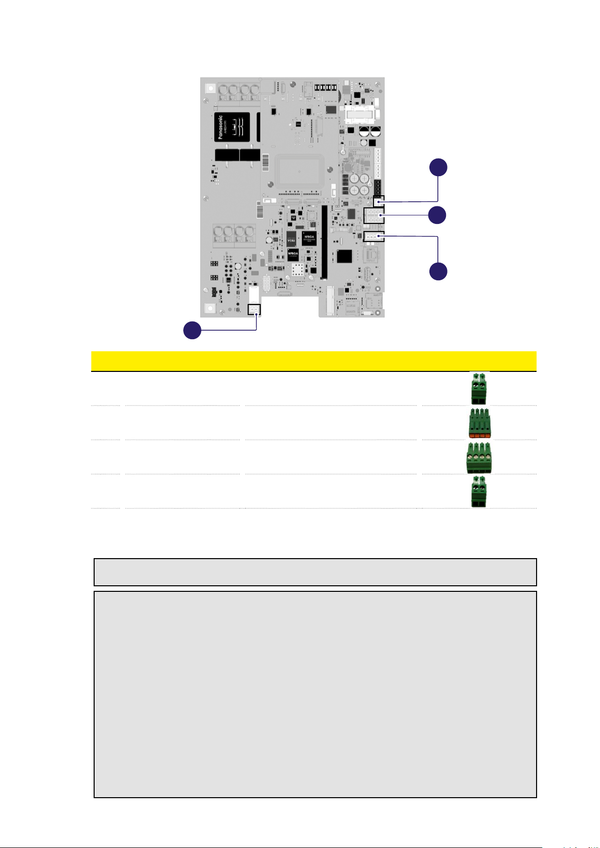
02
03
01
04
N Port types Functionality Picture
01
J4
Analog input 3,3 V
Max. current 330 mA
Pin 1 and 2: T connection
02
J5
4+4 poles RS-485
RS-485 ModBus for Master-Slave or
REACT 2 communication
03
J6
4 poles RS-485
RS-485 ModBus for external MID Meter
04
J31
Normally open dry contact
3 A 250 VAC
Command for upstream switching device
3.4 Space and positioning
READ THE MANUAL –EBefore choosing where to install the product, consult your electric
vehicle manual and follow any pertinent instructions.
ATTENTION –AMake sure that there are no heat sources, flammable substances or
electromagnetic sources in the installation area, either during installation of the product or
throughout the product’s lifetime.
ATTENTION –AIn addition, the installation site must be sufficiently ventilated to ensure
proper heat dissipation. For versions of the product with mobile cellular or Wi-Fi connection,
ensure that the selected area has cellular reception or Wi-Fi coverage.
ATTENTION –ABefore installation, ensure that the environmental conditions (such as
temperature, altitude and humidity) comply with the product specifications.
ATTENTION –ATo ensure the functionality of the device and to guarantee its proper use
by the user, the space around the device must be clear to allow for air circulation, cable
maneuverability, charging procedures and both routine and non-routine safety maintenance
operations.
ATTENTION –AIn addition, the space needed to park the electric vehicle to be charged
must be taken into account.
19
ATTENTION –AFor locations where the device will be exposed to direct sunlight or weather
for most of the day, it is advisable to install a cover to protect the charging station.
In addition, for semi-public installations it is necessary to:
• Make sure that there are barriers or poles to protect the charging device from collisions;
• Design the parking layout for easy access to the charging cable;
• Provide a safe and comfortable environment for users and to prevent vandalism or theft;
• Install the charging device in a place where it can be clearly seen or monitored;
• Install sufficient lighting around the device.
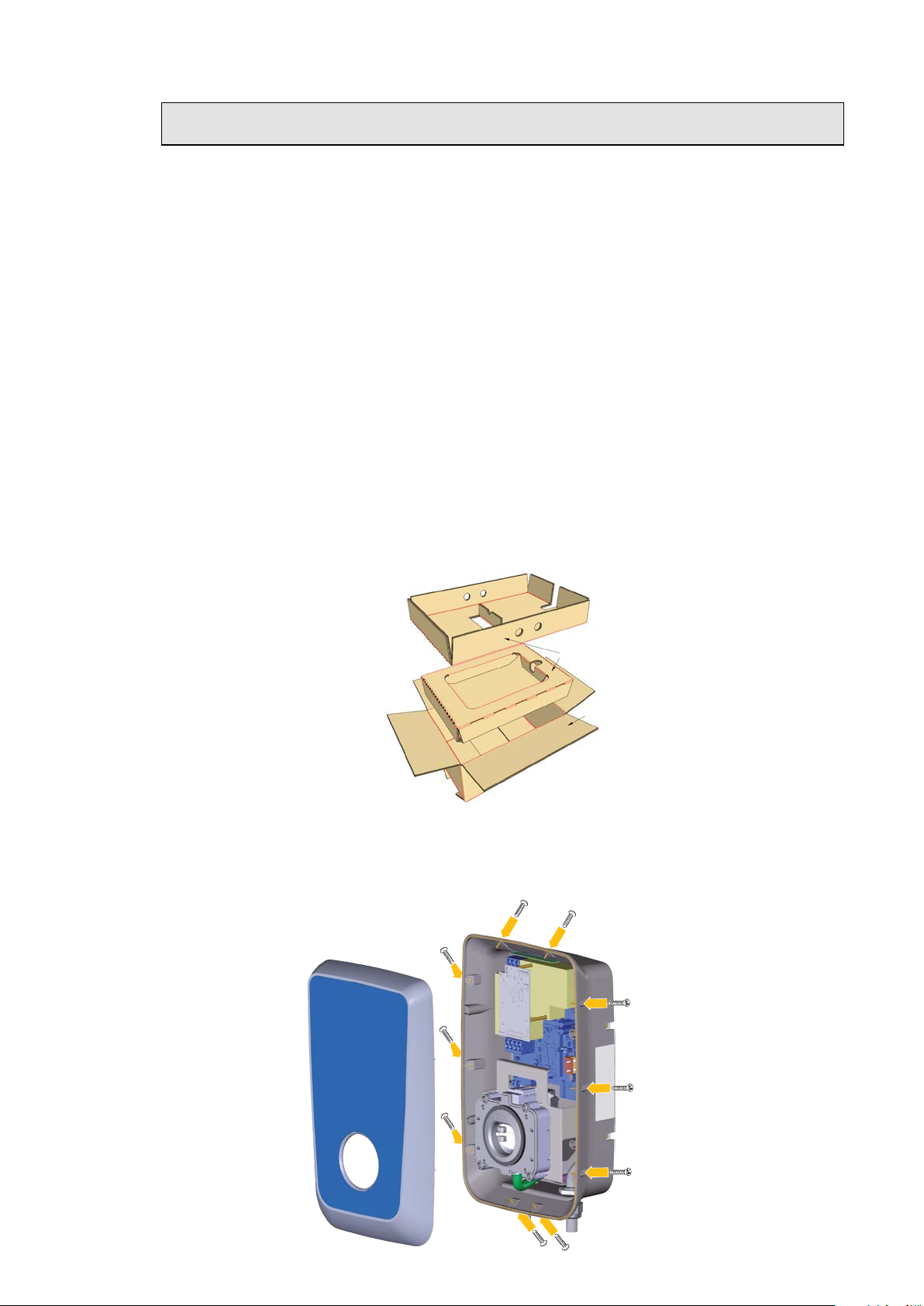
3.5 Unpacking
Before installing the device, it is necessary to check, when unpacking, that the various parts of the
device do not display any physical damage due to impacts, tears or abrasions.
If any damage is detected, the installation procedure must be aborted immediately and technical
support must be contacted.
The various components are protected by packaging and adhesive tape: before installation, each
component must be cleaned of any traces of dust, packaging or adhesive tape.
The images below are for illustrative purposes and may not show all internal components of the
product or may contain negligible differences from the actual configuration.
1.Open the main packaging
2.
Using suitable handling equipment, remove the device from the casing and place it on the work
surface
3.Remove the 10 screws that hold the front cover to the rear casing and separate the two parts of the
product
20
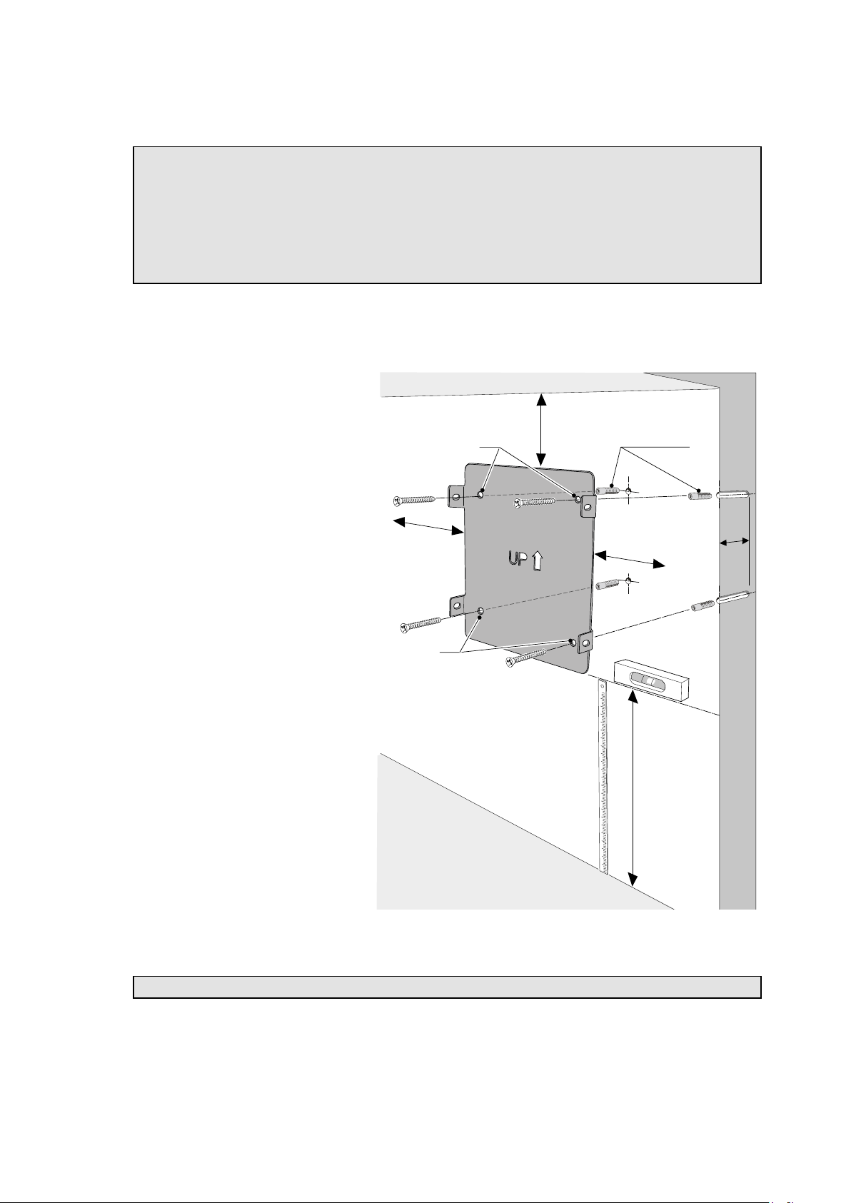
3.6 Wall mounting plate installation
ATTENTION –AThe images below are for illustrative purposes and may not show all
internal components of the product or may contain negligible differences from the actual
configuration.
ATTENTION –AThe product can be installed either on the wall or on a dedicated FIMER
FLEXA Stand. This document shows the installation procedure for wall mounting, while
the installation procedure for the FIMER FLEXA Stand is supplied with the FIMER FLEXA
Stand.
1.
Establish the installation location, taking into account the minimum distances from the
ceiling, walls and floor provided in the drawing. The installation height of the Wallbox must be
such that the lowest point of the vehicle connector when placed in its resting position is at a height
of between 1.2 - 1.5 m above ground level, corresponding to the lower edge of the plate.
2.Place the fixing plate on the wall
and use it as a template to make
marks at the fixing holes (a) using
a marker or pencil. N.B. Pay
attention to the orientation of
the plate. To ensure a more
precise final position, it is best to
use a spirit level to check the
correct alignment of the plate to
the wall when marking.
3.
Remove the plate from the wall
and, using a drill, make 4 holes
(a) Ø 8 mm at the previously
drawn marks. The minimum depth
of the hole must be 60 mm. Then
remove any drilling residue from
the holes.
4.
Separate the 4 screws from the
respective 4 wall plugs Ø 8 x 40
mm (supplied) The wall plugs
supplied are universal, suitable
for solid or cavity brick walls. For
installation on walls made of
different materials (e.g.
plasterboard) specific plugs are
required, which must be installed
after the maximum permissible
load has been verified.
5.
Insert the 4 plugs into the holes
just made. Place the fixing plate
on the wall, matching the 4 holes
in the plate to the 4 holes just
drilled in the wall.
6.
Secure the plate by screwing the 4 screws previously removed from the wall plugs into the
corresponding plugs set into the wall.
NOTE –DMeasurements are in mm.
Ø 8 x 40
(a)
(a)
≥ 500
1200 ÷ 1500
≥
250
60
≥
250
Table of contents
Other Fimer Automobile Batteries Charger manuals

Popular Automobile Batteries Charger manuals by other brands


EnerCharge
EnerCharge DCW Wallbox operating manual

Eaton
Eaton Green Motion DC 66 user manual

Circontrol
Circontrol Genion One installation manual

FRONIUS
FRONIUS Acctiva Professional 42 user manual

Radio Shack
Radio Shack Gigaware 20-449 quick start guide

EnerCharge
EnerCharge ECC 320 Single operating manual


