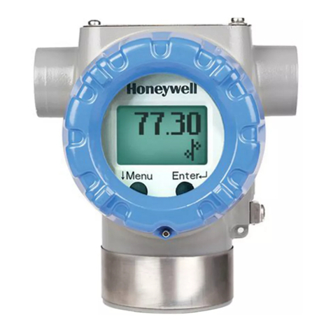
FineTek ECP1 User manual

Contents
1. Reading Labels...............................................................................................................1
2. Product Warranty...........................................................................................................2
2.1 New Product Warranty...............................................................................................2
2.2 Repair Warranty ........................................................................................................2
2.3 Service Network ........................................................................................................3
3. Product Inspection.........................................................................................................4
3.1 Check Content...........................................................................................................4
3.2 Safety Inspection.......................................................................................................4
4. Product Features............................................................................................................5
4.1 Product Features.......................................................................................................5
4.2 Working Principles.....................................................................................................5
4.3 Mechanical Drawing..................................................................................................5
4.4 Product Applications..................................................................................................5
5. Product Specifications ..................................................................................................6
5.1 Product Applications..................................................................................................6
5.2 Panel.........................................................................................................................6
5.3 Appearance and Dimension......................................................................................7
5.4 Hole Dimension.........................................................................................................7
5.5 Ordering Information .................................................................................................8
5.6 Wiring Instructions.....................................................................................................9
6. Installation Instructions...............................................................................................10
6.1 Environmental Safety..............................................................................................10
6.2 Install.......................................................................................................................10
6.3 Installation of Circuits..............................................................................................10
7. Operating Instructions.................................................................................................11
7.1 Button Functions .....................................................................................................11
7.2 Description..............................................................................................................12
7.3 Information on Commands......................................................................................13
7.4 Examples ................................................................................................................14
8. Transportation And Storage........................................................................................15
8.1 Transportation requirements...................................................................................15
9. Maintenance .................................................................................................................15
9.1 Daily Care ...............................................................................................................15
10. Error Message And Troubleshooting .......................................................................15

1
1. Reading Labels
Thanks for purchasing FineTek’s Product. This operation manual describes the
product features, working principles, operation and maintenance methods. It
makes the user fully understand how to use the product correctly, so as to prevent
dangerous situations such as device damage or operator injury.
➢Please read this operation manual completely and carefully before using the product.
➢Please contact the company if this operation manual can’t satisfy your demands.
➢The content of the operation manual is updated based on the version upgrade,
which will be uploaded to the website for the user to access.
➢Please don’t disassemble or repair the product on your own, as this will
make you disqualified from availing of the warranty service. Please send the
product back to the company for repair and calibration, or just contact the
company.
➢Explanation of warning signs:
Danger→ It indicates that wrong operation will cause death or major disasters.
Note→ It indicates that wrong operation will cause injury and device damage to
some extent.
Electric shock→ It warns of possible electric shock.
Fire→ It warns of possible fire.
Prohibited→ It indicates the prohibited wrong behavior.

2
2. Product Warranty
2.1 New Product Warranty
➢Wedon’t charge for the inspection, part/s and repair for the product of the
company that has a defect within 12 months from the delivery date and meets
the warranty terms.
➢If the product defect is not due to human error during its transportation, user
may
➢change to a new unit from the company within 7 days from delivery date.
➢When the product needs to be sent back to the factory for repair, please send
the whole set, and don’t disassemble the parts. Moreover, please be sure it is
completely packed to avoid damage and causing more loss and defect during
the transportation.
➢The warranty is not available for causes that fall under the following
circumstances, for which the company shall charge for the inspection, part/s
and repair according to the actual condition:
◆The product or its parts are beyond the warranty period.
◆Fault or damage is caused by not following the instruction and use
environment described on the operation manual.
◆The product damage is caused by a force majeure factor (natural
disasters, floods, fire, earthquakes, lightning, typhoon, etc.), human
destruction (scratches, dropping, latch broken, tapping, cracks and
punching), human error (using improper voltage, high-humidity, water
leakage, stain, corrosion, loss, improper storage, etc.) and other
abnormal factors.
◆The damage is caused by the customer or the 3rd party through the
installation, addition, expansion, modification and repair of parts not
authorized or certified by the company.
◆The volume label information is wrongor unclear, sothe product serial
numbercan’t be confirmed.
2.2 Repair Warranty
A 6-month warranty service is provided for the repaired part of the product, during
which the same product can be repaired free of charge in case of the same fault.

3
2.3 Service Network
Company
Address
Telephon
Fax
Taipei Headquarters
(Taiwan)
No.16, Tzuchiang St., Tucheng
Industrial Park, New Taipei City
23678
+886 2 2269 6789
+886 2 2268 6682
Taichung
Sales office
(Taiwan)
+886 4 2465 2820
+886 4 2463 9926
Kaohsiung
Sales office
(Taiwan)
+886 7 333 6968
+886 7 536 8758
Fine automation
Co., Ltd.
(China)
No. 451, Duhui Road, Zhuanqiao
Township, Minhang District,
Shanghai City 201109
+86 021 64907260
+86 021 6490 7276
Aplus FineTek
(Sensor Inc.)
355 S. Lemon Ave, Suite D,
Walnut, CA 91789
1 909 598 2488
1 909 598 3188
FineTek Pte Ltd.
(Singapore Branch)
37 Kaki Bukit Place, Level 4
Singapore 416215
+65 6452 6340
+65 6734 1878
FineTek GmbH
(Germany Branch)
Bei den Kämpen 26
21220 Seevetal-Ramelsloh,
Germany
+49 (0) 4185 8083 12
+49 (0) 4185 8083 80
FineTek Co., Ltd.
(Indonesia Branch)
PERGUDANGAN TUNAS BITUNG
JL. Raya Serang KM. 13,8, Blok
C3 No. 12&15, Bitung Cikupa,
Tangerang 15710
+62 (21) 2923 1688
+62 (21) 2923 1988

4
3. Product Inspection
3.1 Check Content
➢Sensor x 1
➢Fixating buckle x 1; countersunk screw x 2; nut x 2
➢Cable x 1
➢Operation manual x 1
3.2 Safety Inspection
➢Please check whether the external package is deformed or damaged. Please
remember to take a picture for evidence for compensation later.
➢After unpacking, please check whether the content is deformed or damaged,
or has any quality problem. Please remember to take a picture for evidence
for compensation later.
➢After unpacking, please check whether the content is consistent with the
ordering info,
and whether the quantity is right.
➢Please contact the company within 7 days if any of the above situations occur
(attach the picture together with your complaint). Otherwise, we won’t
compensate for, change or repair the product defect.

5
4. Product Features
4.1 Product Features
➢Dual-color LED and red-text alarm displays
➢Analog 4–20 mA output that allows continuous detection of pressure values
➢Anti-corrosion structural design that is suitable for minimally corrosive solution
➢Quick release mount to facilitate calibration and replacement
➢Dual NPN/PNP output that makes pressure control quicker and more convenient
➢IO-Link compatibility to make system integration easier
4.2 Working Principles
With the piezoresistive pressure sensor, as soon as changes in environmental
pressure are detected, the thin film deformation on the pressure sensor
changes too, and the piezoresistive material on the thin film experiences
deformation accordingly. The resistance changes as such as well. Such
resistance change, once read and processed through the Wheatstone bridge
and the amplifier circuit, can be used to measure the size of pressure.
4.3 Mechanical Drawing
4.4 Product Applications
This product is applied to a modularized pressure meter where air, water, and solution with
a pH value are used.

6
5. Product Specifications
5.1 Product Applications
5.2 Panel
There are 4 push buttons on the panel for adjustment of parameters. There are two output
indicators (OUT1/OUT2) and 5 pressure units for selection and shift in display.
Power supply
DC 12~36V
Power consumption
<50mA (@24V unloaded)
Operating temperature
−10 to 60°C
Working medium
Liquid/Slight corrosive liquid/air
Accuracy
±1.5%F.S.
Temperature coefficient
±0.1%F.S./ °C (25°C as the baseline)
NPN/PNP output
current
Maximum pressure tolerance of 30 V/100 mA and breakover
residual voltage of < 1.5 V
NPN/PNP protective
current
180mA
NPN/PNP short-circuit
protection
Yes
Delay time
1.5 ms, 20 ms, 100 ms, 500 ms, 1,000 ms, 2,000 ms, 5,000 ms
Current output
4~20mA
Max. Load resistance
When the power voltage is 12V: 300Ω
When the power voltage is 24V: 500Ω
Linearity: ±1%F.S.
Accuracy : ±2.5%F.S. (ambient temperature of 25 ± 3°C)
Display unit
MPa, kPa, kgf / cm², bar, psi
Display method
Dual-color LED
Display color
Red/Green
Number of digits
displayed
4 (7 segments)
Action indicator
It is lit when the output is ON OUT1 and OUT2: Red
Dimensions
61mm*61mm

7
5.3 Appearance and Dimension
5.4 Hole Dimension
On the installation disc, it is required to make diagonal holes with a diameter of 3.2
mm according to the cross-sectional view B-B above; use the countersunk screws
to hold the disk onto the equipment.
In addition, it is required to make holes with a diameter greater than 51.2 and
smaller than 54 mm according to the forgoing drawing to allow buckling and fixation
once the display pressure meter is inserted into the installation disc.
Cross-sectional view
A-A
Cross-sectional view
B-B

8
5.5 Ordering Information

9
5.6 Wiring Instructions
Quick joint used for the ECP and the cable for
connecting the six conductors of the cable
(1) Brown: 4–20 mA
(2) Green: Control box cover
(3) Blue: OUT1
(4) Black: GND
(5) Red: 24V
(6) Orange: OUT2
Information on OUT1/OUT2 connection:
➢R1 and R2 mean the loads of OUT1 and OUT2.
➢When the system experiences abnormalities, to protect the sensor against
Information on the 4–20 mA connector:
The third pin (brown line) is where the 4–20 mA current is output and is
connected to the input terminal of the positive end of the current meter.
The second pin (black line) is 0V and is connected to the input terminal of the
negative end of the current meter.
5
1
4
Current meter

10
6. Installation Instructions
6.1 Environmental Safety
➢Storage temperature: -40°C ~85°C (-40°F~185°F)
➢Operating temperature: -10°C~60°C (-14°F~140°F)
➢Supply power: 12 VDC ~ 36 VDC
➢Output load current: Max, 50 mA
6.2 Install
Once holes are made on the instrument panel according to Section 5, use the countersunk
screws and nuts (follow the red arrows), and secure the snap disc onto the instrument panel
first. Then, tilt the ECP pressure meter by around 30 degrees. Penetrate it through the snap
disc and let the fixating buckle of the snap disc enter the slot. Turn the ECP pressure meter
clockwise till the pressure meter is in the same orientation as the snap disc and this
completes the installation process.
6.3 Installation of Circuits
Once wiring is completed according to Section 5, finish installing the ECP pressure meter. Link and
insert the quick joint of the cable in the arrow-indicated direction to complete installation of the
circuit.
ECP pressure meter
ECP snap disc
Instrument panel

11
7. Operating Instructions
7.1 Button Functions
Quick key:
➢Press and hold for 3 seconds to initialize pressure
➢Press and hold for 3 seconds to shift (LOCK/UNLK)
➢Press to quickly shift the unit
➢Press to enter the menu in an unlocked state
General operation:
Press Access the next-level menu/enter for confirmation
Press Shift on same-level menu; enter the digit to shift
Press Adjust the value up
Press Return to the previous-level menu (without storing changes to parameters)

12
7.2 Description
7.3
00.00 OUT1
OUT2
Mode
ENT
➔
Type
➔
HiPt
➔
LoPt
➔
Dely
➔
Mode
Type
➔
HiPt
➔
LoPt
➔
Dely
➔
ENT ENT
ENT
ENT
ENT
ENT
ENT
ENT
ENT
ENT
ENT
ENT
NC/NO
PNP/NPN
2.00 UP 調整數值;
➔切換位數;
ENT確認
➔切換選項
ENT確認
➔切換選項
ENT確認
1.00 UP 調整數值;
➔切換位數;
ENT確認
20 ➔切換選項
ENT確認
NC/NO
PNP/NPN
4.00 UP 調整數值;
➔切換位數;
ENT確認
➔切換選項
ENT確認
➔切換選項
ENT確認
3.00 UP 調整數值;
➔切換位數;
ENT確認
20 ➔切換選項
ENT確認
Shift options
to confirm
to adjust the value;
the digit;
to confirm
to adjust the value;
the digit;
to confirm
options
to confirm
options
to confirm
options
to confirm
to adjust the value;
the digit;
to confirm
to adjust the value;
the digit;
to confirm
options
to confirm
Shift options
to confirm
Shift options
to confirm
(Default: NC)
(Default: NPN)
(Default: NC)
(Default: NPN)

13
7.4 Information on Commands
Level 1 menu:
OUT1 (output settings for the first group)
OUT2 (output settings for the second group)
Level 2 menu: (Level 3 options in red, without entering Mode >NC alternating display)
OUT1 ➔
Mode: OUT1 connection mode options; one can choose normally closed (NC) and normally
open (NO) modes
Type: OUT1 connection type options; one can choose NPN and PNP
HiPT: OUT1 connection activation values; it is activated when the measurement is greater
than this setting
LoPT: OUT1 connection homing values; it homes when the measurement is smaller than
this setting
Dely: Delay time in activation of OUT1.
OUT2 ➔
Mode: OUT2 connection mode options; one can choose normally closed (NC) and normally
open (NO) modes
Type: OUT2 connection type options; one can choose NPN and PNP
HiPT: OUT2 connection homing values; it homes when the measurement is greater than
this setting
LoPT: OUT2 connection activation values; it is activated when the measurement is greater
than this setting
Dely: Delay time in activation of OUT2.
Note: Dely (1.5/20/100/500/1000/2000/5000(ms))

14
7.5 Examples
The default value of OUT1 LoPt is 1kgf/cm2 and that of HiPt is 2 kgf/cm2
Once the measured pressure is greater than HiPt 2 kgf/cm2, the On/Off joint OUT1 starts to
act and the font color turns red.
Once the measured pressure is below LoPt 1 kgf/cm2, the On/Off joint OUT1 starts to
initialize and the font color turns green.
Once the measured pressure is greater than OU2 LoPt 3 kgf/cm2, the On/Off joint OUT2
starts to act.
Once the measured pressure is greater than OU2 HiPt 4 kgf/cm2, the On/Off joint OUT2
starts to home.
The OUT2 joint only acts when the measured pressure is between LoPt and HiPt.
Font color

15
8. Transportation And Storage
8.1 Transportation requirements
To prevent the ECP Pressure Guage from damage during the transportation, please
keep the packaging condition as how it was when it was shipped from the factory
before arriving at the installation site. The storage conditions should meet the
following:
➢Appropriate rainproof and damp-proof treatment must be conducted .
➢Vibration must be reduced and collision with other objects must be prevented
during its transportation.
➢The storage temperature must be in the range of -40~70°C
➢The humidity should be lower than 80%
9. Maintenance
9.1 Daily Care
Periodically check the pressure sensing port to see if it is clogged by foreign matters or
damaged; if it is seriously clogged, clean it. If it is damaged, replace the equipment.
When equipment is removed and before it is re-installed, confirm carefully if pressure is
released from pressurized pipes to avoid leakage of liquids from the pipes.
The disposal of equipment shall be based on local national regulations in an
environmentally friendly way.
In the case of return, please make sure that the product is not contaminated, particularly
by hazardous or poisonous substances. For the transport, suitable packaging is required
to avoid damaging the equipment.
10. Error Message And Troubleshooting
Abnormality
Possible causes
Solution
No display
No power supply
Check the power line and
repair it.
No display
Failure to meet product
specification requirements
in terms of power
Confirm that power supply is
12–30 Vdc and correct it
No response with On/Off
Abnormal wiring
Check wiring, terminal pin,
and correct it
No response with On/Off
Insufficient power supply to
drive output
Check power supply (it has
to be >12Vdc) and correct it
The switch signal is not
stable and works
intermittently.
Make sure the wiring of the
switch signal and power
cable terminals does not
become lose or come off.
Confirm the wire pin again to
ensure the correction
connection of the lines.
Table of contents
Other FineTek Measuring Instrument manuals

FineTek
FineTek EPF Series User manual
FineTek
FineTek EF Technical manual
FineTek
FineTek EPD34 User manual

FineTek
FineTek ECP2 User manual
FineTek
FineTek EPD30 Technical manual
FineTek
FineTek EE310 User manual

FineTek
FineTek EPD36 Technical manual
FineTek
FineTek JTR Series Technical manual
FineTek
FineTek EPR5 User manual

FineTek
FineTek EDX2 User manual

