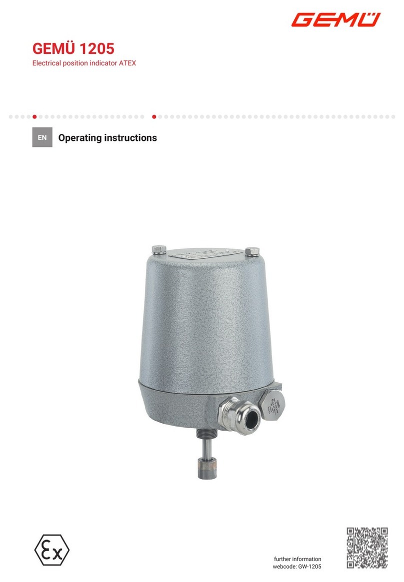
FineTek EF Technical manual

I
EF+EG Calibration and setting
Operation Instruction
FineTek Co., Ltd
No.16, Tzuchiang St., Tucheng Industrial Park, New Taipei City 236, Taiwan
Tel: 886-2-22696789 Fax: 886-2-22686682
08-EFEG-B0-EK,04/10/2012

I
Contents
1. Reading Before Use...................................................................................1
2. Warranty .....................................................................................................2
2.1 Warranty for New Product..............................................................................2
2.2 Warranty Under Maintenance........................................................................2
2.3 Service Network...............................................................................................3
3. Product Inspection ....................................................................................4
3.1 Product Checking.............................................................................................4
3.2 Safety Inspection .............................................................................................4
3.3 Transportation safety.......................................................................................4
4. Product Introduction .................................................................................5
4.1 Product Features .............................................................................................5
4.2 Working Principle.............................................................................................5
4.3 Machine composition.......................................................................................6
4.4 Product Application..........................................................................................6
5. Product Specification................................................................................7
5.1 Probe Specification..........................................................................................7
5.1.1Panel Introduction ..............................................................................7
5.1.2 External Dimension...........................................................................7
5.1.3 Hole Dimension.................................................................................7
5.1.4 Order Information..............................................................................7
5.2 Electrical Specification....................................................................................8
5.3 Wiring Information............................................................................................8
6. Installation..................................................................................................9
6.1 Environmental Safety......................................................................................9
6.2 Product Installation..........................................................................................9
6.3 Electric Circuit Installment............................................................................12
6.4 Precautions.....................................................................................................13
7. Operation Instructions ............................................................................14
7.1 EG Magnetostrictive Level Transmitter Wiring Connection
Considerations...............................................................................................14
7.2 Button Function Explanation........................................................................14
7.3 Operation Procedure.....................................................................................15
7.4 Order Instruction............................................................................................16
7.5 Model Code Explanation...............................................................................16
8. Technical Words explanation..................................................................17

II
9. Functions..................................................................................................18
9.1 Quick Installation Introduction......................................................................18
9.2 Advanced Settings.........................................................................................20
10. Storage & Transportation Requirements .............................................21
10.1 Environmental Requirements ....................................................................21
10.2 Transportation Requirements ....................................................................21
11. Maintenance ...........................................................................................22
11.1 Regular Maintenance..................................................................................22
11.2 Parts Installation...........................................................................................22
12. Trouble Shooting ...................................................................................23

1
1. Reading Before Use
Thank you for your purchase for FineTek product. This menu introduces the product
features, operations, maintenance and troubleshooting to help user get familiar with
product, and avoid harm by unperoper use. Before use, please carefully study the
details of product. Extra support requirement can be found at www.fine-tek.com or
directly contact us by telephone and facsimile. On line revision will issue at web site
and not further inform. User can get newest support and download at ww.fine-tek.com.
In case of any unexpected problem, don’t disassembe it by yourself or you will lose the
product guarantee. Contact us, if you have any question hard to be defined.
Symbol Instruction
Danger→ Deathly danger or significant harm might be caused with unproper
use.
Notice→ Damage to user or equipment with unproper use.
Electric Shock→ Notice for Electric Shock.
Fire→ Notice for Fire.
Prohibit→ Prohibit for Wrong Operation.

2
2. Warranty
2.1 Warranty for New Product
All FineTek products will get one year guarantee in regular operation. Product within
guarantee period will get service and no charge for any nominal fee. User finds any
defect during delivery process or not be broken by wrong operation that can ask return
or replace. In maintenance, user has the obligation to send all complete parts back to
FineTek in well carefully package. Over range operation, over charge or any abnormal
operation will excess out the guarantee range. Product not in guarantee period and
condition will charge necessary fee for the repair or replace.
Things below will not in guarantee coverage and will be charged service fee:
Expire the guarantee date.
Not properly use according to operation manual.
Irresistible environment effects or natural disaster (earthquake, flood disaster, fire,
lighting stroke, hurricane)
Human-made damage (scratch, cutting, throwing down, hammering) or abnormal
operation (over power range, over ambient condition, over range operation,
corrosion, watering, electric charge),non-proved third-party device connection or
expend, replace non-proved components or module.
2.2 Warranty Under Maintenance
Maintenance Guarantee: All the products will get six months guarantee service since
repair or replace components. During six months, any fault caused in same will be
serviced in free charge.

3
2.3 Service Network
Beanch
Address
Tel
Fax
Head Quarter
(Taiwan)
No.16, Tzuchiang St., Tucheng
Industrial Park, New Taipei City 236,
Taiwan
+886 2-2269-6789
+886 2-2268-6682
Fineautomation
Co.,Ltd. (China)
No.451 DuHui Rd, MinHang District,
Shanghai, China 201109
+86 216490-7260
+86 216490-7276
Beijing Branch
Office (China)
No.8 GuanGqu Men Street, Block A,
Room 191
+86 108353-5118
+86 108353-2816
Guangzhou
Branch Office
(China)
No.536 LongKou Rd West, Grass
Park B-18C TianHe District,
Guangzhou, China
+86 203846-1387
+86 203846-1397
Wuhan Branch
Office(China)
No.14 ZhongZan Rd, Century
square , Block B, WuChang District,
Wuhan, China
+86 27-8733-2314
+86 27-8733-2341
Jinan Branch
Office (China)
No.44 HongLou Rd South, HuiKe
Park Building 6, Unit 2, Room 1601,
LicHeng District, Jinan, China
+86 531-83173652
+86 31-83173670
Nanjing Branch
(China)
Everest Building Room 1709, 19
Cutral Road, Nanjing Drum Tower
District, Nanjing, China
+86 025-83176832
+86 025-83176831
Finetek Pte Ltd.
(Singapore)
No. 11 Kaki Bukit Road 1 #04-01
Eunos Technolink 415939,
Singapore
+65 6452-6340
+65 6734-1878
FineTeK GmbH
(Germany)
Frankfurter Str. 62, OG D-65428
Ruesselsehim, Germany
+49 (0)6142-17608-16
+49 (0)142-17608-20

4
3. Product Inspection
3.1 Product Checking
1 pcs EG Magnetostrictive Level Transmitter sensor, 1 pcs EF By-Pass chamber, 1 pcs
cable (standard M12 connector, length 2M)
3.2 Safety Inspection
a. Open box
b. Please check the packaging before unpacking whether deformed or damaged. If
packing is damged,please take photos as evidence for the basis for subsequent
compensation
c. After unpacking, please check the contents and product quality and take photos as
evidence for future use.
d. After unpacking, please immediately check whether your purchase contents and
quantity are correct.
e. In case any anomaly in products contents, please contact our company within 7 days of
receiving the product (together with photo). Otherwise, company will not liable for
replacement or free of charge repair.
3.3 Transportation safety
Skip

5
4. Product Introduction
4.1 Product Features
This product is an integration of benefits of EF Magnetic Float type By-Pass Level Indicator
with easy level observation and EG Magnetostrictive Level Transmitter with high accuracy,
quick response time into one unit. This unit can easily installed on the side of the tank for
level measurement and control.
4.2 Working Principle
EG Magnetostrictive Level Transmitter & EF By-Pass Level Indicator uses the magnetic field
interaction between Magnetic flag and Magnetic float inside the By-Pass chamber to
measure the liquid level. Magnetic flags outside the chamber will flip together with the
magnetic float inside the By-Pass chamber with the rise in liquid level.At the same time, EG
Magnetostrictive Level Transmitter continuously sends spiral magnetic field current pulse
signal. When these signal meets the magnetic field of float produces seismic waves. EG
calculates the travel time and speed of the signal formed by two different magnetic field to
find out the absolute level of liquid.

6
4.3 Machine composition
4.4 Product Application
Textiles Dyeing equipments
Waste Water Treatment
Chemical Machinery (Raw material tanks, storage tanks, reaction tanks)
Power plant
Pharmaceutical equipments (medicine raw materials storage tanks)
Kerosene, Heavy oil, fuel storage tanks
Petrochemical industry
Water processing industry (water storage, hot water recycling equipments etc)

7
5. Product Specification
5.1 Probe Specification
Skip
5.1.1Panel Introduction
Skip
5.1.2 External Dimension
Skip
5.1.3 Hole Dimension
Skip
5.1.4 Order Information
During model selection of EF Series, please select EG Transmitter parts code as described
below:
Transmitter:
A: EG37 Intrinsically Safe Explosion-Proof Modbus RS-485 Output
(EG371BQ00-00AB-L)
B: EG37 Intrinsically Safe Explosion-Proof 4~20mA(Bottom~Top)Output
(EG371BQ00-00A0-L
C: EG37 Intrinsically Safe Explosion-Proof 4~20mA(Top~Bottom)Reverse Direction Output
(EG371BQ00-00B0-L)
D: EG31Modbus RS-485 Output
(EG311BQ00-00AB-L)
E: EG31 4~20mA(Bottom~Top)Output
(EG311BQ00-00A0-L)
F: EG31 4~20mA(Top~Bottom)Reverse Direction Output
(EG311BQ00-00B0-L)
※EG Transmitter is not suitable for By-Pass Indicator with Dual Flange,
Blanket type, Jacket type & Removable Insulation type.

8
5.2 Electrical Specification
Power supply: 24VDC±10% (EG Magnetostrictive Level Transmitter)
5.3 Wiring Information
1. Single / Double float +RS485
2. Double float + Dual current output
Brown
Blue
Green
Black
Brown
Blue
Green
Black
RS485
RS485
Loop Power (CH1)
Loop Power (CH1)
Analog Output 2 (CH2)
Analog Output 2 (CH2)
Loop Power (CH1)
Loop Power (CH1)
Loop Power 24Vdc 10%
Loop Power 24Vdc 10%
13
4
2
13
4
2

9
6. Installation
6.1 Environmental Safety
Skip
6.2 Product Installation
EF By-Pass Level Indicator Chamber Installation:
a. Firstly read and understand “Product Safety Installation Precautions”
b. Before installation remove from the top and bottom flanges.
c. Please ensure the flange hole position and diameter is in similar position with the flange
of the tank extension pipe.
d. Please ensure flange welding of the extension pipe with the tank meets the industrial
safety standards.
e. After welding of extension pipe flange, please tightly fix both flanges together screw and
bolts.
f. Before welding of extension pipe with the tank, check the alignment of hole of both the
flanges. For Top mounting type, chamber must be perpendicular to ground level (or
fluid).It is advised to use bubble level scale to ensure the installation is perpendicular.
Lower Pipe (shield pipe) is not supposed to touch tank bottom. Float is also not
supposed to expose outside shield pipe. For top mounting type,if chamber length is
more than 1.5m (for plastic type) & 2m (for metal type), it is advised to use support
bracket to prevent bending of the chamber.
Pipe not to touch tank
bottom & float shouldn’t
come out
anti-dust plug
Chamber Support
Tank opening welding
Tank opening welding
anti-dust plug

10
g. After welding, dismantle indicator for check-up, cleaning etc, then add gasket between
flange before re-installing By-Pass Level Indicator.
h. Before opening hole and welding, please measure all the every dimension of By-Pass
indicator.
g. Please ensure that top & bottom holes are identical in a straight line and
perpendicular to ground. Also check if both flanges position are identical in a
straight line. Before starting welding process, please confirm that above
mentioned requirements are fulfilled.
h. After installation use a magnet to test the if the indicator are working properly.
i. Above liquid level flag color is white and below liquid level is red. Indicator can be
tested by slowly filling tank to full and then empty the tank.
j. All the above installation processing such as opening holes, welding etc must
follow industry standards, environmental standards.
Flag Display Installation
a. Indicator flag at the bottom indicate zero level and top flag indicate maximum level (float
standard are based on specific gravity of water as standard medium). If the medium is
not water, flag will little ahead or lag behind to the real level in the tank.
If specific gravity of liquid is more than water, height of float will rise (compared to
float in water). At the same time, flags rotation standards will also rise.
If specific gravity of liquid is less than water, height of float will drop (compared to
float in water). At the same time, flags rotation standards will also drop.
water
S.G=1
mercury
S.G>1
water
S.G=1
Oil
S.G<1

11
b. If the float specific gravity is not changed together with liquid, calibration is required for
minimum and maximum level. This will solve the problem of over indication or
incomplete indication of flags. But this will not overcome the issue of flag indication
ahead or lag behind real liquid level. Magnetic float (near top of chamber & bottom of
chamber) have blind distance which leads to flags don’t turn over with liquid level.
c. Please check if flags are fixed in a straight line and stick together with the chamber. Also
make sure distance between indicators and chamber is maintained similar from top to
bottom.
d. Please make sure that distance between two Metallic belt is not much. Every 1.5 meter
length require at one metallic belt tied.
e. For adjustment of indicator please loose the screw, adjust and tighten it back. Please
ensure not to tighten to much which can damage the instrument or welding.
EG Installation
a. Firstly dismantle the metallic belt from the chamber, check the all the fastening
components.
b. Fastening base position needs to be placed on the side of the flag indicators. Firstly
assemble the position of the fastener with the chamber and then tighten the metallic
belt.
Metallic belt
Anti-heat Gasket
Top blind distance
C-C distance
Bottom blind distance
Top Process Connection
Bottom Process Connection
Tightening Screw
Metallic belt
Metallic belt
Metallic belt
Anti-heat Gasket
Transmitter

12
c. Firstly tight M6 screw and then fix Magnetostrictive sensor with M4 screws.
d. Please ensure the metallic belt is in the right position and tightly holding the chamber,
indicator and EG sensor.
No.
Parts
Material Specifications
Quantity
1
EG
Standard/ Top conduit
1
2
EF
Top cover+1/2”PT plug/ bottom double
flange+1/2”PT plug
1
3
Sheet Metal Cover
ψ16 stem 2.5t SUS304
n
4
Sheet Metal Seat
ψ16 stem 3t SUS304
n
5
M4 Hexagonal Nut
M4*8L SUS304
n
6
M6 Hexagonal Nut
M4*8L SUS304
n*2
7
M4 Nut
M4 SUS304
n
8
Spring Washer
M6 SUS304 ATEX
n*2
* For NO3/ NO4/ NO5 are same as the metallic belt (EFA-2000)
6.3 Electric Circuit Installment
Skip

13
6.4 Precautions
Magnetostrictive Level Transmitter (EG):
a. Power supply for Magnetostictive Level Transmitter is 24Vdc ±10%. For high accuracy
and normal operation of the sensor, please ensure during installation don’t bend or
touch the metallic chamber.
b. Please ensure the sensor is not dismantle at any time, which can influence normal
operations.
c. During installation, please ensure that sensor is not squeezed or deformed. If unable to
measure level due to bending or deformation, immediately send sensor to our factory for
calibration.
d. For transportation safety, the sensor is packed with extreme vibration safety using
bubble bag and spongy pad etc.
e. Please ensure not to open the housing, which can affect the accuracy of the sensor.
By-Pass Level Indicator (EF):
a. By-Pass Indicator must be installed vertical with the vessel, and vertical deviation must
be less than 3°
b. Please check S.G of the liquid medium and S.G indicated on the tag are identical.
c. Liquid level ascending rate must be less that 1cm per second.
d. During installation please check that no external particles enter the chamber which can
harm the float.
e. Magnetic switch is influenced by any line of magnetic influx to give switching output.
During installation, please ensure no external magnetic field is present 10 cm from
Magnetic switch.
f. During installation, magnetic float needs to be protected from severe shocking, which
may damage the floats.
g. If external particles have entered the chamber during installation, please dismantle the
lower flange to clean.Also clean the floats before tightening the flange back. Please
ensure the float arrow symbol↑ is placed upwards.
h. Custom-made floats don’t have arrow symbol. In this case heavier side of the float is
placed upwards.

14
7. Operation Instructions
7.1 EG Magnetostrictive Level Transmitter Wiring Connection Considerations
a. During wiring connection, please check that power supply is disconnected.
b. During peeling of wire, please ensure that there is no naked wire which can touch other
wires resulting in signal short circuit.
c. For safety of the sensor, please check there is no naked wire touching any other metallic
object near the sensors.
d. Please ensure that wiring can’t get any contact with water, rain water to avoid short
circuit.
7.2 Button Function Explanation
skip

15
7.3 Operation Procedure
Yes
Start
Provide EG Power Supply
Connect with RS-485
Start Calibration Program MLMAS.EXE
Set Connection Parameters
Move Float with Reference Point
(Zero point)
Read Reference Point
(Zero point) Distance for float
Compensate enter Float
Adjustment
Whether reference point
match (or 0 mm)
Set SPAN value
(correspond to full scale current)
Set Zero value
(correspond to zero scale current)
End
No

16
7.4 Order Instruction
Skip
7.5 Model Code Explanation
Skip

17
8. Technical Words explanation
Skip
This manual suits for next models
1
Table of contents
Other FineTek Measuring Instrument manuals
FineTek
FineTek EE310 User manual
FineTek
FineTek EPD34 User manual
FineTek
FineTek SC38 User manual

FineTek
FineTek EPD36 Technical manual

FineTek
FineTek EPR5 User manual
FineTek
FineTek EPD30 Technical manual
FineTek
FineTek EPR1 Series Technical manual

FineTek
FineTek EDX2 User manual

FineTek
FineTek JTR Series Technical manual

FineTek
FineTek ECP1 User manual
