FineTek EPD34 User manual

Contents
1. Reading Labels...................................................................................................................1
2. Product Warranty...............................................................................................................2
2.1 New Product Warranty.................................................................................................2
2.2 Repair Warranty............................................................................................................2
2.3 Service Network............................................................................................................3
3. Product Inspection ............................................................................................................4
3.1 Check Content...............................................................................................................4
3.2 Safety Inspection ..........................................................................................................4
4. Summary ..............................................................................................................................4
5. Product Features................................................................................................................5
6. Applicable Scope ...............................................................................................................5
7. Environmental Condition.................................................................................................5
8. Working Principles ............................................................................................................6
9. Technical Performance.....................................................................................................7
9.1 Execution Standards....................................................................................................7
9.2 Basic Parameters and Performance Indicators.......................................................8
9.2.1 Technical Specification Table.................................................................................8
9.2.2 Accuracy class & tolerance.....................................................................................9
9.2.3 Recommended Flow Range for Tube Diameters................................................9
9.2.4 Pressure resistance and inner diameter specification for various tube
diameters............................................................................................................................10
9.2.5 Lining Material.........................................................................................................10
9.2.6 Electrode Material ..................................................................................................11
9.2.7 Housing Protection Rating(IP)..............................................................................11
10. Appearance and Dimension.......................................................................................12
10.1 JIS 10K & 20 K..........................................................................................................12
10.2 ANSI 150Lbs & 300Lbs...........................................................................................13
10.3 DIN PN40 & PN16 & PN10.....................................................................................14
11. Installation .......................................................................................................................15
11.1 Conditions required to guarantee the measurement accuracy of the
electromagnetic flow meter:.............................................................................................15
11.2 Safety Measures .....................................................................................................15
11.3 Inspection before Installation.............................................................................15
11.4 Handling....................................................................................................................16
11.5 Correct Installation ................................................................................................16
11.6 Notes for Installation on the Pipe.....................................................................18
11.7 Grounding Requirements.....................................................................................19

12. Wiring and Using ..........................................................................................................20
12.1 Wiring .........................................................................................................................20
12.1.1 Notes for Wiring....................................................................................................20
12.1.2 Diagram of Sensor Wiring Terminal...................................................................20
12.1.3 Diagram of Transmitter Wiring Terminal ...........................................................21
12.1.4 Signal Electrical Cable Wiring.............................................................................22
12.2 Input / Output Function Wiring................................................................................23
12.2.1 4-20mA Current output.........................................................................................23
12.2.2 Pulse Output..........................................................................................................23
12.2.3 RS-485 Communication.......................................................................................23
12.2.4 Digital output 1 (DO1)...........................................................................................24
12.2.5 Digital output 1 (DO2)...........................................................................................24
12.2.6 Digital input (DI).....................................................................................................24
12.2.7 Analogy input (AI)..................................................................................................25
13. Inspection before Power-On.......................................................................................25
14. Parameter Functions.....................................................................................................26
14.1 Procedure for Menu Setting....................................................................................26
14.1.1Functions of the Display Interface.......................................................................26
14.1.2 Button Functions in Parameter Setting Status:................................................26
14.2 Various Parameter Setting Ranges.......................................................................27
15. Ordering Information ....................................................................................................30
16. Transportation and Storage........................................................................................31
17. Fault Inspection and Repair........................................................................................32
18. MODBUS Communication Protocol..........................................................................33

1
1. Reading Labels
Thanks for purchasing FineTek’s Product. This operation manual describes the product
features, working principles, operation and maintenance methods. It makes the user fully
understand how to use the product correctly, so as to prevent dangerous situations such as
device damage or operator injury.
Please read this operation manual completely and carefully before using the product.
Please contact the company if this operation manual can’t satisfy your demands.
The content of the operation manual is updated based on the version upgrade, which will
be uploaded to the website for the user to access.
Please don’t disassemble or repair the product on your own, as this will make you
disqualified from availing of the warranty service. Please send the product back to the
company for repair and calibration, or just contact the company.
Explanation of warning signs:
Danger→It indicates that wrong operation will cause death or major disasters.
Note→It indicates that wrong operation will cause injury and device damage to some
extent.
Electric shock→It warns of possible electric shock.
Fire→It warns of possible fire.
Prohibited→It indicates the prohibited wrong behavior.

2
2. Product Warranty
2.1 New Product Warranty
We don’t charge for the inspection, part/s and repair for the product of the company that
has a defect within 12 months from the delivery date and meets the warranty terms.
If the product defect is not due to human error during its transportation, user may change
to a new unit from the company within 7 days from delivery date.
When the product needs to be sent back to the factory for repair, please send the whole
set, and don’t disassemble the parts. Moreover, please be sure it is completely packed
to avoid damage and causing more loss and defect during the transportation.
The warranty is not available for causes that fall under the following circumstances, for
which the company shall charge for the inspection, part/s and repair according to the
actual condition:
The product or its parts are beyond the warranty period.
Fault or damage is caused by not following the instruction and use environment
described on the operation manual.
The product damage is caused by a force majeure factor (natural disasters, floods,
fire, earthquakes, lightning, typhoon, etc.), human destruction (scratches, dropping,
latch broken, tapping, cracks and punching), human error (using improper voltage,
high-humidity, water leakage, stain, corrosion, loss, improper storage, etc.) and
other abnormal factors.
The damage is caused by the customer or the 3rd party through the installation,
addition, expansion, modification and repair of parts not authorized or certified by
the company.
The volume label information is wrong or unclear, so the product serial number can’t
be confirmed.
2.2 Repair Warranty
A 6-month warranty service is provided for the repaired part of the product, during which the
same product can be repaired free of charge in case of the same fault.

3
2.3 Service Network
Company
Address
Telephone
Fax
Taipei Headquarters
(Taiwan)
No.16, Tzuchiang St., Tucheng
Industrial Park, New Taipei City
23678
+886 2-2269-6789
+886 2-2268-6682
Taichung Sales office
(Taiwan)
+886 4-2465-2820
+886 4-2463-9926
Kaohsiung Sales office
(Taiwan)
+886 7-333-6968
+886 7-536-8758
Shanghai Fine Auto Co., Ltd.
(China)
No. 451, Duhui Road, Zhuanqiao
Township, Minhang District,
Shanghai City 201109
+86 021-64907260
+86 021-6490-7276
Beijing Sales office
(China)
Room D921, Fuli Mogan Center,
No. 6,Taiping Street, Xicheng
District, Beijing City(100050)
+86 010-59361535
+86 010-59361512
Guangzhou Sales office
(China)
Room 1605, 1606, Jinxiu Joint
Business Building, No. 1, Tianhe
Road, Yuexiu District, Guangzhou
City (510075)
+86 020-38461387
+86 02038461397
Wuhan Sales office
(China)
Room 2101-2102, Building B,
Century Plaza, No. 14, Zhongnan
Road, Wuchang District, Wuhan
City
+86 27-87332314
+86 27-87332324
+86 027-87332341
Jinan Sales office
(China)
Room 1222, 1223, Tianye
International Plaza, No. 264,
Quancheng Road, Lixia District,
Jinan City (250011)
+86 531-83173652
+86 531-83173670
+86 31-83173670
Nanjing Sales office
(China)
Room 1709, Everest Building, No.
19, Zhongyang Road, Gulou
District, Nanjing City (210008)
+86 025-83176832
+86 025-83176833
+86 025-83176831
Chengdu Sales office
(China)
Room 1509, Building 2,
LANDMARK, No. 51, S 4th
Section, 2nd Ring Road,
Wuhou District, Chengdu
City (610041)
+86 028-84087414
+86 028-85590364
+86 028-84087413
Shenyang Sales office
(China)
Room 2501, Building B, 1st
Mall, No. 1-1, Jianshe
Middle Road, Tiexi District,
Shenyang District(110026)
+86 024-85611026
+86 024-85611053
Zhengzhou Sales office
(China)
Room 1304, Wancheng
Times Sqaure, No.9,
Jianshe Road, Zhongyuan
District, Zhengzhou City
(450007)
+86 0371-55638443
+86 0371-55638440
Finetek Pte Ltd.
(Singapore Branch)
60 Kaki Bukit Place #07-06,
Eunos Techpark 2 Lobby B,
Singapore
415979.415979
+65 6452-6340
+65 6734-1878
FineTeK GmbH
(Germany Branch)
Frankfurter Str. 62, OG D-65428
Ruesselsehim, Germany
+49 (0)6142-17608-0
+49 (0)142-17608-20

4
3. Product Inspection
3.1 Check Content
1 flow meter
1 operation manual
1 product inspection sheet
3.2 Safety Inspection
Please check whether the external package is deformed or damaged. Please
remember to take a picture for evidence for compensation later.
After unpacking, please check whether the content is deformed or damaged, or has
any quality problem. Please remember to take a picture for evidence for compensation
later.
After unpacking, please check whether the content is consistent with the ordering info,
and whether the quantity is right.
Please contact the company within 7 days if any of the above situations occur (attach
the picture together with your complaint). Otherwise, we won’t compensate for, change
or repair the product defect.
4. Summary
The company’s electromagnetic flow meter adopts coil excitation, which is more stable than
the traditional magnetism generation. After strict vibration and anti-noise test, it can work
stably and is highly tolerant of complex environments in the industrial field, which also has
a longer life span in practical application.
The electromagnetic flow meter has kept on evolving since its initial development, which is
widely applied in monitoring various industrial fluid pipes, including power generation, water
treatment, food, medication, shipping, dyeing & finishing, and semi-conductor process
industries. With its simple working principle, the electromagnetic flow meter is widely
applicable in various environments as long as the correct model is selected to match the
fluid properties.

5
5. Product Features
The measurement results is not affected by the change of liquid density, viscosity,
temperature, pressure and conductivity.
There are only two measurement points in the measuring tube without baffle and
movable parts, so it won’t cause pressure loss and jam.
It can test the flow for the conducting fluid and the fluidic containing some solid
granules.
The straight tube section required for the installation just needs the upstream front 5D
and downstream 2D of the flow meter without complicated pipeline design.
The measurement turndown ratio can reach 3:100, which can achieve high accuracy
especially for measuring small flow.
It has a self-diagnosis function, which can automatically detect the excited signal,
whether the measuring tube is empty and whether the electrode is stained or damaged.
The lining can be common NBR(Nitrile), high-temperature or acid-proof & alkali-proof
PTFE(Teflon)
The maximum fluidic temperature permitted can reach 120℃(Teflon)
The flow converter setting is simple, with powerful functionality.
6. Applicable Scope
Conductivity: > 5μS/cm
Fluid properties: Pure liquid and fluidic containing some solid granules.
Application industries: Power generation, water treatment, food, medication, shipping,
dying & finishing, and semi-conductor process
7. Environmental Condition
Ambient environment: -40℃~ 70℃
Relative humidity: 5% ~ 95% of RH, without condensing water
Atmospheric pressure: 86 ~ 106 KPa
Power supply: 100~240Vac 50/60Hz

6
Converter
v
8. Working Principles
The working principle of the electromagnetic unit is based on the Faraday law of
electromagnetic induction. When the conductor moves in the magnetic field, it will
generate induced EMF on both sides of the conductor in the orthogonal direction of the
magnetic field direction and the motion direction. The EMF is directly proportional to the
motion speed of the conductor and the magnetic induction intensity.
As shown in <Figure 1>, the conducting fluidic passes through the insulating tube with the
internal diameter of D(m) at the average flowing speed V(m/s) that is equipped with a pair
of measuring electrodes. Moreover, the tube is in a magnetic field with uniform magnetic
induction intensity of B (T). In this case, the electrodes will induce the EMF (E) at the
orthogonal direction of the magnetic field and the flowing direction. According to the law
of electromagnetic induction, E can be written as Equation (1):
Wherein, k is the proportional coefficient.
The volume flow can be written as
From Equation (1) and (2), we can get:
Thus, EMF can be represented as:
When B is a constant in Equation(3)
Equation(3) can be modified as:
It can be concluded that the flow qv is directly
proportional to the EMF E.
<Figure 1>

7
9. Technical Performance
9.1 Execution Standards
IEC 60068-2-3 EN 61326-1:2013
IEC 61326-1 EN 55011:2009/A/:2010
IEC 60092-504 ISO 4064-1
JIS B2220 JIS B7554-1997
ANSI B16.5 DIN 25 Series

8
9.2 Basic Parameters and Performance Indicators
9.2.1 Technical Specification Table
Item
EPD34
Display
LCM 128* 64 pixel backlit type
Buttons
Tri-button operation
Communication interface
RS-485 (Modbus) (Optional support for ZigBee Pro wireless
transmission)
Accuracy
±0.5% of reading@1m/s(0.2% optional)
Reproducibility
0.02 % F.S. @ 0.1~1.0m/s, 0.2% O.R. @ 1.0~10.0 m/s
Operation temperature of lining
NBR:Temperature resistance<80℃, mainly applied in low-concentrated
acid and alkane liquid. With excellent anti-abrasion property, it can
be used to measure liquid with impurities. It is applicable to coal
slurry, mud and industrial sewage.
Neoprene:Temperature resistance <80℃, resistant to general low-
concentrated acid and alkane. It is applicable to industrial sewage
and tap water.
PTFE: Temperature resistance <120℃. With stable chemical properties,
it is mainly applied in strong corrosive medium such as
concentrated acid and alkane or an environment with requirements
for cleanliness. It is applicable to various liquids and chemical
agents in food processing.
Ambien temperature
-40~70℃
Fluidic conductivity
>5uS/cm
Measuring scope
0.1m/s~10m/s
Current output accuracy
0.1% of Pulse Output Accuracy
Temperature coefficient (100ppm/℃)*Note 1
Current output mode
Proactive
Analog output
4~20mA
Maximum load of current output
<700Ω
Alarming current
3.6mA or 22mA
Frequency output scope
2~8KHz
Pulse width
Automatic (pulse width 50%)
Pulse mode
NPN transistor output 32vdc/200mA
Time constant
0~100s
Control output (DO)
NPN transistor output 32vdc/200mA;2-CH
Control input (DI)
Dry contact ON< 200Ω ;
1,000Ω< OFF ; 1-CH
Simulate output (AI)
4~20mA
Baud rate
1200~57600bps
Protection rating
IP67/NEMA 4X
Enclosure material
Aluminum alloy
Input power
AC100~240Vac
Power consumption
<10 W
Wire inlet specification
M20 x1.5*2 Female
signal power cable
< 100m *Note 2
Excitation mode
Pulse DC
Vibration regulation
IEC 60068-2-3
EMC regulation
IEC/EN 61326-1 Class A table 2
Note 1:Combined with FineTek sensor

9
Note 2:When the signal power cable is longer than 50m, the empty tube detection is unavailable.
9.2.2 Accuracy class & tolerance
9.2.3 Recommended Flow Range for Tube Diameters
Pipe diameter
(mm)
Flow range (m3
/ h)
Flowing speed 0.1~1.0m/s
Flowing speed 1.0~10m/s
40
0.45~4.5
4.5~45.2
50
0.71~7.1
7.1~71
65
1.19~11.9
11.9~119
80
1.81~18.1
18.1~181
100
2.83~28.3
28.3~283
125
4.42~44.2
44.2~442
150
6.36~63.6
63.6~636
200
11.3~113
113~1130
250
17.7~177
177~1770
300
25.4~254
254~2540

10
9.2.4 Pressure resistance and inner diameter specification for various tube diameters
9.2.5 Lining Material
Lining material
Main properties
Application scope
PTFE
1. Stable chemical properties,
resistance to various acid,
alkane, and salt solutions and
various organic solvents. It is not
tolerant to the corrosion of CIF3,
high-temperature OF3 and high-
speed liquid oxygen and ozone.
2. The anti-abrasion property is
average.
1. -20~120℃
2. Strong corrosive medium such
as concentrated acid and
alkane.
NBR
1. Excellent flexibility, highly tearing
force capability, good wear
resistance
2. It is resistant to low
concentrations of acid, alkali, salt
solution;It is not tolerant the
corrosion of oxidizing mediums.
1. < 80℃
2. Neutral-strong wearing mineral
pulp, coal slurry and mud slurry
Neoprene
1. Neutral wearing capability
2. It is resistant to low
concentrations of acid, alkali, acid
corrosion.
1. < 80℃
2. Water, Industrial water ,
Seawater
mm Inch JIS mm Inch mm Inch
25 120K - - - -
32 1-1/4 20K - - - -
40 1-1/2 20K - - 38 1.50
50 210K - - 49 1.93
65 2-1/2 10K - - 64 2.52
80 310K - - 77 3.03
100 410K - - 102 4.02
125 510K - - 128 5.04
150 610K - - 151 5.94
200 810K - - 207 8.15
250 10 10K - - 256 10.08
300 12 10K - - 301 11.85
Inner diameter of measurement tube
Nominal diameter
Specification of
measurement tube
NBR
PTFE

11
9.2.6 Electrode Material
Electrode material
Anti-corrosion property
Stainless steel (316L)
It is applied in water, sewage and organic corrosive medium.
Hastelloy alloy
It is resistant to the corrosion of the medium mixture of oxidizing acid
such as Nitric acid, mixed acid or Sulfuric acid. Moreover, it is resistant
to the corrosion of the oxidizing salt such as or other
substances containing oxidants such as the salt solution of
hypochlorous acid above the ambient temperature and sea water.
Titanium
It is resistant to the corrosion of sea water, various oxides, salt solution
of hypochlorous acid, oxidating acid (including fuming Nitric acid) and
organic acid and alkane. It is not resistant to the corrosion of pure
reducing acid (such as Sulfuric acid and Hydrochloric acid). However,
the anti-corrosion property will be greatly degraded if the acid contains
some oxidants.
Tantalum
It has excellent corrosion resistance. Its characteristic is similar to
glass. In addition to hydrofluoric acid , nitric acid , alkali, it could resist
almost all chemical medium (including boiling hydrochloric acid, nitric
acid and sulfuric acid below 175’C). It could not resist corrosion in
alkali.
9.2.7 Housing Protection Rating(IP)
Transmitter:IP67
Sensor: IP67

12
10. Appearance and Dimension
10.1 JIS 10K & 20 K
Connection specification
JIS 20K
Nominal diameter(mm)
40
50
65
80
100
125
150
200
250
300
Lining material
PTFE
Length
L
200
200
200
200
250
250
300
350
400
500
External diameter
ϕD
140
155
175
200
225
270
305
350
430
480
PCD
ϕC
105
120
140
160
185
225
260
305
380
430
Flange thickness
t
18
18
20
22
24
26
28
30
34
36
Inclined angle of screw
hole
θ°
45
22.5
22.5
22.5
22.5
22.5
15
15
15
11.25
Diameter of screw hole
θh
19
19
23
23
23
25
25
25
27
27
Quantity of screw holes
N
4
8
8
8
8
8
12
12
12
16
Height of sensor casing
H1
125
125
145
145
195
195
270
305
365
406
Total height
H2
276
.4
283.9
303.9
316.4
353.9
376.4
440
476
547
594
Weight (kg)
-
5.5
3
6.17
7.43
10.70
14.87
22.01
29.48
41.82
72.6
8
92.6
0
Remarks: For DN40~DN80, the lining protective ring is 2mm, so the total length of the flow meter
shall be increased by 4mm. For DN100~DN200, the lining protective ring is 0.5mm, so the total
length of the flow meter shall be increased by 1mm;
*1:total height(H2) tolerance is 2mm
*2:The weight is only for sensor casing, the meter weight 2.06 KGs is not included.
Connection specification
JIS 10K
Nominal diameter(mm)
40
50
65
80
100
125
150
200
250
300
Lining material
PTFE
Length
L
200
200
200
200
250
250
300
350
400
500
External diameter
ϕD
140
155
175
185
210
250
280
330
400
445
PCD
ϕC
105
120
140
150
175
210
240
290
355
400
Flange thickness
t
14
14
16
16
16
20
22
22
24
24
Inclined angle of screw
hole
θ°
45
45
45
22.5
22.5
22.5
22.5
15
15
11.25
Diameter of screw hole
θh
19
19
19
19
19
19
23
23
25
25
Quantity of screw holes
N
4
4
4
8
8
8
8
12
12
16
Height of sensor casing
H1
125
125
145
145
195
195
270
305
365
406
Total height
H2
276
.4
283
.9
303.9
308.9
346.4
366.4
429
468
534
578
Weight (kg)
-
5.2
5
6.1
3
7.43
8.32
11.35
15.95
21.9
6
31.68
52.48
68.00

13
10.2 ANSI 150Lbs & 300Lbs
Connection specification
ANSI 150Lbs
Nominal diameter(mm)
40
50
65
80
100
125
150
200
250
300
Lining material
PTFE
Length
L
200
200
200
200
250
250
300
350
400
500
External diameter
ϕD
127
152
178
190
229
254
279.4
342.9
406.4
482.6
PCD
ϕC
98.4
120.
6
139.7
152.4
190.5
215.
9
241.3
298.4
361.9
431.8
Flange thickness
t
15.9
17.4
20.6
22.2
22.2
22.2
23.8
27.0
28.6
30.2
Inclined angle of
screw hole
θ°
45
45
45
45
22.5
22.5
22.5
22.5
15.0
15
Diameter of screw
hole
θh
15.9
19
19
19
19
22.2
22.2
22.2
25.4
25.4
Quantity of screw
holes
N
4
4
4
4
8
8
8
8
12
12
Height of sensor
casing
H1
125
125
145
145
195
195
265
305
365
406
Total height
H2
322
335
358
364
408
421
478
525
589
647
Weight (kg)
-
4.93
6.77
9.23
10.70
16.27
19.4
1
25.48
42.62
65.68
98
Connection specification
ANSI 300Lbs
Nominal diameter(mm)
40
50
65
80
100
125
150
200
250
300
Lining material
PTFE
Length
L
200
200
200
200
250
250
300
350
400
500
External diameter
ϕD
156
165
190
210
254
279
317.5
381
444.5
520.7
PCD
ϕC
114.3
127
149.2
168.3
200
235
269.9
330.2
387.35
450.85
Flange thickness
t
19.0
20.6
23.8
27.0
30.2
33.3
34.9
39.7
46.0
49.2
Inclined angle of
screw hole
θ°
45
22.5
22.5
22.5
22.5
22.5
15.0
15.0
11.3
11.3
Diameter of screw
hole
θh
22.2
19
22.2
22.2
22.2
22.2
22.2
25.4
28.6
31.8
Quantity of screw
holes
N
4
8
8
8
8
8
12
12
16
16
Height of sensor
casing
H1
125
125
145
145
195
195
265
305
365
406
Total height
H2
337
341
364
374
421
433
495
542
606
664
Weight (kg)
-
9.08
10.3
2
12.78
16.45
26.6
2
32.9
6
42.28
67.62
98.88
145
Remarks: For DN40~DN80, the lining protective ring is 2mm, so the total length of the flow meter
shall be increased by 4mm. For DN100~DN200, the lining protective ring is 0.5mm, so the total
length of the flow meter shall be increased by 1mm;
*1:total height(H2) tolerance is 2mm
*2:The weight is only for sensor casing, the meter weight 2.06 KGs is not included.

14
10.3 DIN PN40 & PN16 & PN10
Connection specification
DIN PN40
DIN PN16
Nominal diameter(mm)
40
50
65
80
65
80
100
125
150
200
Lining material
PTFE
Length
L
200
200
200
200
200
200
250
250
300
350
External diameter
ϕD
150
165
185
200
185
200
220
250
285
340
PCD
ϕC
110
125
145
160
145
160
180
210
240
295
Flange thickness
t
18
20
22
24
18
20
20
22
22
24
Inclined angle of
screw hole
θ°
45
45
22.5
22.5
45
22.5
22.5
22.5
22.5
15
Diameter of screw
hole
θh
18
18
18
18
18
18
18
18
22
22
Quantity of screw
holes
N
4
4
8
8
4
8
8
8
8
12
Height of sensor
casing
H1
125
125
145
145
145
145
195
195
265
305
Total height
H2
334
341
361
369
361
369
404
419
484
524
Weight (kg)
-
5.53
6.17
7.43
10.7
7.03
10.70
14.0
7
19.4
1
26.68
38.42
Connection specification
DIN PN10
Nominal diameter(mm)
200
250
300
Lining material
PTFE
Length
L
200
200
200
External diameter
ϕD
150
165
185
PCD
ϕC
110
125
145
Flange thickness
t
18
20
22
Inclined angle of
screw hole
θ°
45
45
22.5
Diameter of screw
hole
θh
18
18
18
Quantity of screw
holes
N
4
4
8
Height of sensor
casing
H1
125
125
145
Total height
H2
334
341
361
Weight (kg)
-
5.53
6.17
7.43
Remarks: For DN40~DN80, the lining protective ring is 2mm, so the total length of the flow meter
shall be increased by 4mm. For DN100~DN200, the lining protective ring is 0.5mm, so the total
length of the flow meter shall be increased by 1mm;
*1:total height(H2) tolerance is 2mm
*2:The weight is only for sensor casing, the meter weight 2.06 KGs is not included.

15
11. Installation
The design, test and power supply for the flow meter are based on the related regulations.
User must strictly follow the instructions to guarantee the safe operation and normal working
of the flow meter.
11.1 Conditions required to guarantee the measurement accuracy of the electromagnetic
flow meter:
The test liquid is conducting.
The measuring pipe must be filled with liquid.
The test liquid must be uniform, so asto prevent the non-uniform conductivity(which
will result in serious interference). If you need to add some chemicals dynamically,
it should be added in the downstream of the flow meter.
The electromagnetic flow meter must be well grounded. Especially in the plastic pipe,
the grounding ring must be installed in order to perform solid grounding.
The straight tube section is required to be at least 5D at the flow meter inlet (internal
diameter of the measuring pipe), and at least 2D at the flow meter outlet.
The flow meter should be kept away from strong EMI, and it should not be installed
near the large motors or transformers.
11.2 Safety Measures
To guarantee human and device safety, the instructions below must be followed:
Before selecting the location and installing the flow meter, the user should carefully
read the related parts in this manual, and consider the safety requirements for the
flow meter, related devices and machine body environment.
The flow meter installation and repair must beperformed by the personnel with some
flow meter knowledge.
The flow meter sensors and pipes must be correctly installed, and the sealing must
be safe and reliable. The liquid pressure should not exceed the maximum working
pressure described on the flow meter specification.
Proper measures must be taken to prevent electrical shock accident.
The handling equipment of the flow meter should meet the safety requirements.
11.3 Inspection before Installation
Check whether the flange, lining, casing and outgoing line sleeve are damaged.
Open the box cover to check whether the wiring printed circuit is loosened or
damaged.
Check whether the model number on the nameplate is consistent with the order
information.

16
11.4 Handling
The flow meter must be handled with the correct handling method. The safety load and
protection action of the handling equipment should meet the related regulations. The
transmitter box (for integrated flow meter) or enclosure (for separated flow meter) must
not be tied up to handle the flow meter.
11.5 Correct Installation
It is very important to select the installation site and install the flow meter correctly. If
any mistake is made during the installation, it will affect the measuring accuracy or the
life span of the flow meter, or even cause damage. When selecting the installation site,
please pay special attention to the following:
a. The axis of the measuring electrode must be approximate to the horizontal direction
(Generally, the angle from the level line is within 10°.)
b. The measuring pipe must be filled with liquid.
c. The flow meter must be equipped with the straight tube section in the length of at
least 5×D at the front side (D is the internal diameter of the flow meter), and the
straight tube section in the length of at least 2×D at the rear side (D is the internal
diameter of the flow meter).
10°
10°
5D

17
d. The flowing direction of the fluidic is the same as the arrow direction on the flow meter.
e. Please prevent the vacuum in the pipe, which will damage the lining of the flow meter.
f. The flow meter must be free from strong electromagnetic field. The magnetic intensity
of the flow meter installation site must be smaller than 400A/m.
(It should not be installed near large motors or transformers)。
g. There should be enough space left surrounding the flow meter for installation and repair.
h. If the measuring pipe vibrates, a support frame should be set up on both sides of the flow meter.
i. When measuring the mixture of different media, the distance between the mixing point and the
flow meter must be 30×D at least (D is the internal diameter of the flow meter)).
j. For convenient cleaning and maintenance of the flow meter, a bypass pipe must be installed.
k. When installing the flow meter of the PTFE lining, the bolt connecting two flanges should
be fastened evenly. Otherwise, it will damage the PTFE lining. Please use the torque
wrench as much as possible.
l. The flow meter should be protected from strong vibration and great temperature change.
In the meantime, damage of the corrosive liquid on the flow meter should be prevented.
m. If the flow meter is installed at a position with direct sunlight, shielding facilities should
be set up.
n. When installing the sensor, the measuring pipe and the process pipe must be on the
same axial line. For the senor with the nominal diameter of DN50 or below, the axial line
deviation should not exceed 2mm. For those of DN65~DN150, the axial line deviation
should not exceed 3mm. For those of ≥DN200, the axial line deviation should not exceed
4mm.
o. The shim installed between the flanges should have excellent anti-corrosion property.
The shim should not intrude in the pipe, which will block the flowing fluidic
p. Fasten the bolts and screws of the flow meter. The screw threads should be undamaged
with good lubrication condition. The bolts with torque wrench must be fastened based
on the flange size and torque.
q. When welding or flame-cutting the pipes near the sensor, isolation measure must be
conducted, so as to prevent the lining from heating. Moreover, the flow meter must be
powered off, or it will damage the flow meter.
Table of contents
Other FineTek Measuring Instrument manuals

FineTek
FineTek EDX2 User manual
FineTek
FineTek JTR Series Technical manual
FineTek
FineTek EPD30 Technical manual
FineTek
FineTek EPR1 Series Technical manual
FineTek
FineTek EPR5 User manual

FineTek
FineTek EPD36 Technical manual
FineTek
FineTek SC38 User manual
FineTek
FineTek ECP1 User manual
FineTek
FineTek EPF Series User manual
FineTek
FineTek EF Technical manual
Popular Measuring Instrument manuals by other brands

YOKOGAWA
YOKOGAWA GD402G /M1 user manual
DynAmp
DynAmp LKAT Plus Installation, operation and service manual
Norland
Norland 388S631 Repair Procedure
VOLTCRAFT
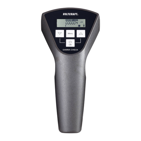
VOLTCRAFT Gamma Check Pro operating instructions

SAEHAN
SAEHAN DHD-3 user manual
Endress+Hauser
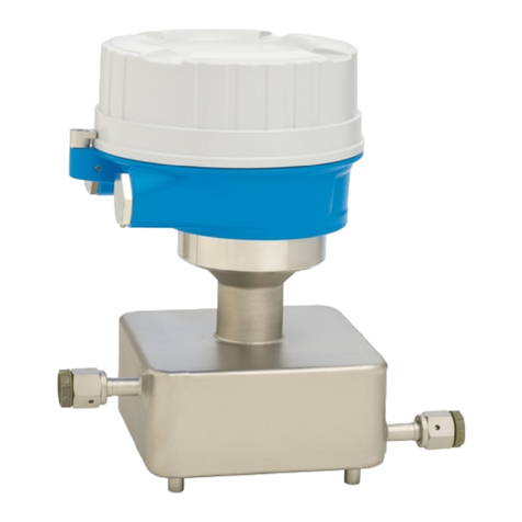
Endress+Hauser Proline Cubemass C 100 PROFIBUS DP operating instructions

