manuals.online logo
Brands
  1. Home
  2. •
  3. Brands
  4. •
  5. FineTek
  6. •
  7. Switch
  8. •
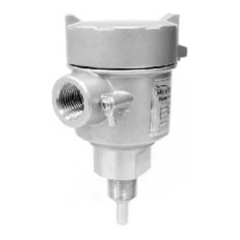
  9. FineTek SA140 User manual

FineTek SA140 User manual

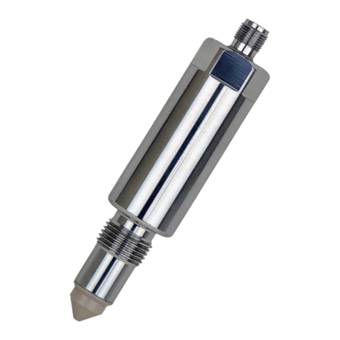
Capacitance switches rely on electrical capacitance theory (the ability of a
medium to store electrical energy). The switch detects a level change of a
tanks medium by calculating the capacitance between the tank wall and the
probe. All mediums have differing conductivity and dielectric constants which
affects their energy sstorage capability. When the probe comes into contact
with the medium, it can detect a change in the surrounding capacitance and
this actuates the switch accordingly.
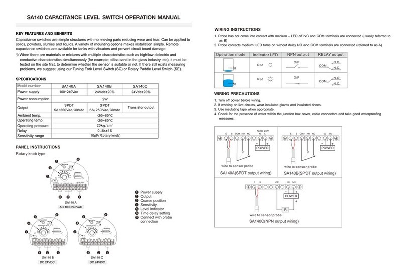
SA140 CAPACITANCE LEVEL SWITCH OPERATION MANUAL
WORKING PRINCIPLE
KEY FEATURES AND BENEFITS
Power supply Output Coarse position
Sensitivity Level indicator Time delay setting
Connect with probe connection
SPECIFICATIONS
PANEL INSTRUCTIONS
Capacitance switches are simple structures with no moving parts reducing wear and tear. Can be
applied to solids, powders, slurries and liquids. A variety of mounting options makes installation simple.
Remote capacitance switches are available for tanks with vibrators and prevent circuit board damage.
Model number SA140A SA140B SA140C
110/220Vac±10% 24V±20% 24V±20%
2W
Transistor output
-20~80°C

20kg/cm
SPDT
5A/250Vac/30Vdc
SPDT
5A/250Vac/30Vdc
-20~60°C
0~8s±1S
14.6pF
Power supply
Power
consumption
Output
Ambient temp.
Operating temp.
Operating
pressure
Delay
Sensitivity range
SA140A SA140B SA140C
Operation mode Indicator LED NPN output
Red
Red
COM.
COM.
O/P
O/P
N.O.
N.C.
N.O.
N.C.
RELAY output
SA140A(SPDT output wiring)
E S COM NO NC AC0V 110V 220V E S COM NO NC 0V 24V
POWER
+
-
E S O/P 0V 24V
POWER
+
-
R
+
SA140B(SPDT output wiring) SA140C(SPDT output wiring)
WIRING INSTRUCTIONS
2. Probe contacts medium: LED turns on without delay NO and COM terminals are connected (referred
to as A)
1. Probe has not come into contact with medium – LED off NC and COM terminals are connected
(usually referred to as B)
WIRING PRECAUTIONS
4. Check for the presence of water within the junction box cover, cable connectors and take good
waterproofing measures.
2. If working on live circuits, wear insulated gloves and insulated shoes.
1. Turn off power before wiring.
3. Use insulating tape when appropriate.
wire to sensor probe wire to sensor probe wire to sensor probe
SENSITIVITY-No.
SERIES No.
COARSE
DELAY
INDICATOR
NC
NO
COM
SE
24V
0V
SENSITIVITY-No.
SERIES No.
COARSE
DELAY
INDICATOR
SENSITIVITY ADJ
220V
110V
AC0V
NC
NO
COM
SE
SENSITIVITY-No.
SERIES No.
COARSE
DELAY
INDICATOR
SENSITIVITY ADJ
O/P
SE
24V
0V
SW 1 2 3 4 5 6
H L
ON
SW 1 2 3 4 5 6
H L
ON
SW 1 2 3 4 5 6
H L
ON
888
8
2. The insulated probe should protrude at
least 30mm from the tank wall.
1. Top mounted: Minimum distance should
be 300mm between the probe and wall.
3. Side mounting angle: roughly 20
degrees.
4. The conduit and wiring should face
downward.
INSTALLATION (SEE THE SKETCH BELOW)
300mm
30mm
No induction body
20°
300mm
MAINTENANCE
08-SA140-B2-EM,02/13/2019
Tel: 886-2-22696789 Fax: 886-2-22686682
Email: [email protected] http://www.fine-tek.com
No.16, Tzuchiang St., Tucheng Industrial Park, New Taipei City 23678, Taiwan.
FineTek Co. , Ltd.
Conditions Possible
malfunctions
Noticeable
problems Solutions
Housing leaking
Level changes but
switch doesn't
actuate
Level rises and
falls but switch only
actuates once
Switch signal
unstable and
sometimes jumps
or fluctuates
Housing is loose Rattling/ looks loose Tighten and lock
Sealing loosens Usually due to age Replace item
Loose conduit Loose or slack wiring Tighten conduit screw
Conduit not facing
downwards Conduit facing upwards Change conduit
position
Electrical cable not
facing downward Cable Facing upwards As Above
Cable diameter too small Loose cabling Use f8~f10mm cable
Sensitivity knob needs
readjustment
Knob has changed from
original position Reset sensitivity
Power source or circuit
problem Check power and circuits Correct any wiring issues
Static electricity damage Dusty, powdery
environment
Switch to FineTek static
model
Medium dielectric
constant too low
Try using course and
fine tuning to detect
substance
C2 capacitor needs
changing
Tank contains high
percentage of water
vapor
Probe has water droplets Use a coated probe
model
The probe is touching
the tank wall Probe is grounded Remove the cause of the
probe and grounding
contact
Static electricity damage Dusty, powdery
environment
Switch to FineTek static
model
Medium dielectric
constant too low
Try using course and fine
tuning to detect
substance
C2 capacitor needs
changing
Terminal connections are
loose
Dusty, powdery
environment Tighten connections
Connection thread loose Dusty, powdery
environment
Tighten connection
thread or flange
Old or defective
wiring/circuit Dusty, powdery
environment Change wiring
Power supply
abnormality Dusty, powdery
environment
Restore the required
power supply
Tank vibration has
caused loosening of
electrical circuits/parts
Check tank for vibration Switch to remote model
(SA140).
5. Switch “SENSITIVITY ADJ 1” to “ON” (Fig. 2). Check if LED indicator is OFF. If yes, rough
adjustment is complete. If not, kindly ad the rough adjustment again.
6. After complete above steps, if there is any malfunction occurred, switch “SENSITIVITY ADJ 3 and
4” to “ON”(Fig. 3).
1. After installation or hold this sensor in hand, connect with power and make sure there is no
material within 300 mm around the probe.
※“SENSITIVITY ADJ” 1~6 represent its dielectric value, 1=0.3pF, 2=0.5pF, 3=1pF, 4=2pF, 5=4pF,
6=6.8p, total 14.6pF. Increase the dielectric value to decrease the sensitivity. Decrease the
dielectric value to Increase the sensitivity.
3. Use flat-head screwdriver to turn “Coarse” clockwisely for rough adjustment until LED indicator is
ON.
If LED is keeping “OFF” and not able to switch it “ON”, For example, the dielectric value is 5 pF.
Switch on “SENSITIVITY ADJ” 3 and 5 do the rough adjustment again.
4. If LED is keeping “ON” and not able to switch it “OFF”. For example, the dielectric value is 10.8
pF. Switch on “SENSITIVITY ADJ” 5 and 6 do the rough adjustment again.
2. Fine adjustment, switch “SENSITIVITY ADJ” 1~6 to “OFF” position. (Fig. 1)
SENSITIVITY ADJUSTMENT
SW 1 2 3 4 5 6
SENSITIVITY ADJ
Fig 1
SW 1 2 3 4 5 6
SENSITIVITY ADJ
Fig 2
SW 1 2 3 4 5 6
SENSITIVITY ADJ
Fig 3

This manual suits for next models

3

Other FineTek Switch manuals

FineTek SA140 User manual

FineTek

FineTek SA140 User manual

FineTek FD7 Series User manual

FineTek

FineTek FD7 Series User manual

FineTek SC28P/N User manual

FineTek

FineTek SC28P/N User manual

FineTek SA27 User manual

FineTek

FineTek SA27 User manual

FineTek SC174X Series User manual

FineTek

FineTek SC174X Series User manual

FineTek SE3X User manual

FineTek

FineTek SE3X User manual

FineTek SP2 User manual

FineTek

FineTek SP2 User manual

FineTek SIS User manual

FineTek

FineTek SIS User manual

Popular Switch manuals by other brands

MORLEY MK-41 manual

MORLEY

MORLEY MK-41 manual

ATEN KH1508Ai user manual

ATEN

ATEN KH1508Ai user manual

EINHELL 41.742.21 Original operating instructions

EINHELL

EINHELL 41.742.21 Original operating instructions

Eaton P1 XM Series Instruction leaflet

Eaton

Eaton P1 XM Series Instruction leaflet

IAS Multipoint 56 Installation and operation

IAS

IAS Multipoint 56 Installation and operation

LDG SLS-2 Operation manual

LDG

LDG SLS-2 Operation manual

Arista DCS-7050TX-48 quick start guide

Arista

Arista DCS-7050TX-48 quick start guide

Lantech IGS-3208MGSFP user manual

Lantech

Lantech IGS-3208MGSFP user manual

Korenix JetNet 4508 Quick installation guide

Korenix

Korenix JetNet 4508 Quick installation guide

Siemens RUGGEDCOM RX1510 installation guide

Siemens

Siemens RUGGEDCOM RX1510 installation guide

Cabletron Systems SmartSwitch 8H02-16 user guide

Cabletron Systems

Cabletron Systems SmartSwitch 8H02-16 user guide

Atop RHG7528 Series Hardware installation guide

Atop

Atop RHG7528 Series Hardware installation guide

Ross Carbonite eXtreme Fan Replacement

Ross

Ross Carbonite eXtreme Fan Replacement

LEGRAND Luxul SW-510-48P-F Setup guide

LEGRAND

LEGRAND Luxul SW-510-48P-F Setup guide

Panasonic AJ8 quick start guide

Panasonic

Panasonic AJ8 quick start guide

NETGEAR GS305Pv3 installation guide

NETGEAR

NETGEAR GS305Pv3 installation guide

Wöhner OMUS 30Compact operating instructions

Wöhner

Wöhner OMUS 30Compact operating instructions

Nortel Passport 4400 Series introduction

Nortel

Nortel Passport 4400 Series introduction

manuals.online logo
manuals.online logoBrands
  • About & Mission
  • Contact us
  • Privacy Policy
  • Terms and Conditions

Copyright 2025 Manuals.Online. All Rights Reserved.