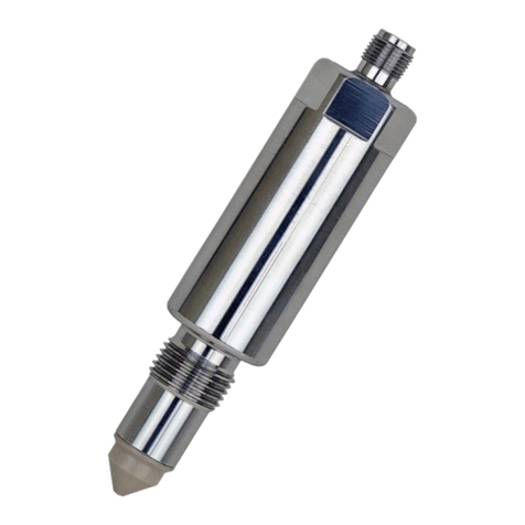
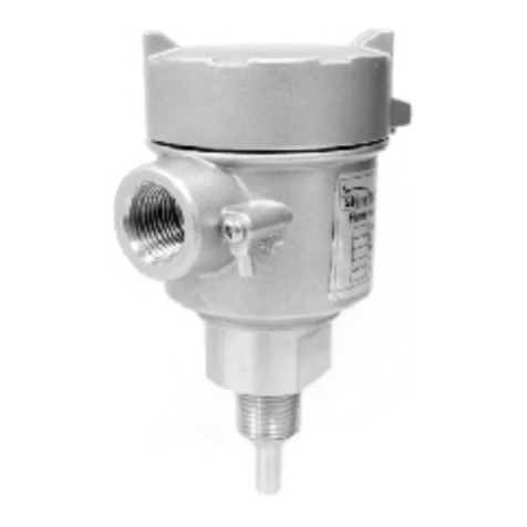
FineTek SC174X Series User manual

The tuning fork level switch is a mechanical resonant device
which excited by piezoelectric (PZT) elements. When the
measured medium comes into contact with the tuning fork, it will
change the feedback resonant frequency due to the damping
resonances between the exciting PZT and receiving PZT. By
detecting the frequency and appropriately tuning the sensitivity
of tuning fork level switch on measured material, such device
can easily operate for monitoring the alarm level of measured
material.
1. Providing a universal power supply for operating in voltage
range of 20 to 250 (Vac / Vdc).
2. No calibration or complex setting procedure are needed,
robust, free of maintenance and operated in diversity
abominable environments.
3. High / Low fail safe modes provide user the safety
monitoring and real time communication.
4. Equipped with Remote Self-Testing function (RST) to
diagnostic the hardware connection with peripherals
Dimensions
Terminals Arrangement :
Power Supply
Power Consumption
Diagnostic Frequency
Fork Length
Operating Humidity
Operating Pressure
Act Time Lag
Medium Density
Output
Fail-safe
Electrical safety
Housing Material
Probe Material
Enclosure Rating
Connection
Mounting
20~250, 50/60 Hz Vac/Vdc
Power consumption£10 VA
350~370 Hz
100 mm
Max extension length: 4 m
20%~80% RH non-condensed
-1~600PSI (40BAR)
3 second
3
Solid:density:³0.07g/cm
3
Liquid:density:³0.7g/cm
Viscosity:1~10000 cSt
0.6 s since the measured material contacted
1-3 s react to the measured material fall off
Relay, SPDT, 3A/250Vac Max.
PNP/NPN 400mA/60 Vac/ Vdc
Remote-test
Green light: indicate power supply
Red light: indicate operating mode
High / Low
Over Voltage category III
Aluminum (ADC-12)
316L/316/304
Ex db llB T4~T6
1"PT(standard)or PF thread
Flange 1"~6" JIS/DIN/ANSI standard or
special specification
Time Delay
Input
Status
1/2"NPT
f27
f113
108
1" PT
105
25
15
SENSITIVITY
HLFSL FSHSIGNAL
PWR
20~250VAC
20~250VDC
SENSITIVITY
HLFSL FSHSIGNAL
PWR
20~250VAC
20~250VDC
FSH:
Operating mode MAX (NC contact)
COM
No
Nc
No
Nc
COM
FSL:
Operating mode Min (NO contact)
COM
No
Nc
COM
No
Nc
Introduction
Feature
RT2 RT1 NC NO N- L+
COM
SC174X Series Tuning Fork Level Switch
Operation Manual
Specification
RT2 RT1 NC2 NO2 N- L+
COM2 NC1 NO1COM1
Relay Output
PNP/NPN Output
L+, N-: Power Supply
NC1, COM1, NO1: Relay Output
NC2, COM2, NO2: Relay Output
RT1, RT2: Remote-Test
: Ground Connection
st
COM1, NO1:1 OutputPNP/NPN
nd
COM2, NO2:2 OutputPNP/NPN
Terminal Function
PWR: Power Supply (Green Light)
SIGNAL: Output Indication (Red Light)
FSH: Power on. The signal LED is on and the relay acts.
While the tuning fork level switch contacts with measured
material, the signal LED is off and the relay is in not act.
FSL: Power on. The signal LED is off and the relay is in not act.
While the tuning fork level switch contacts with measured
material, the signal LED is on and the relay is in act.
SENSITIVITY L: Low Sensitivity
SENSITIVITY H: High Sensitivity
Panel Function
Relay Output
PNP/NPN Output
Output Description
1. Make sure provide power supply (L+/N-) in range of 20~250
(Vac or Vdc,50/60Hz) and output relay (Relay or PNP/NPN
before wiring. Detail please see Fig-1 and Fig-2.
2. RT1 and RT2 are the testing points that easy user to verify
the situation. When the RT1 and RT2 are in electric short, it
means the measured material is in contact with the tuning
fork level switch. The Relay or PNP/NPN should be
activated. In examining the tuning fork level switch, user
will find it keep vibrating.
Fig-1. SPDT contact output model
Fig-2. DPDT contact output model
Refer to the Fig.1-Fig.2, all the wiring should adopt the 18
AWG standard isolation cable and it is compulsory to keep
from the dust in the housing and avoid of electric short. To
prevent the water or moisture penetrating into the housing,
please rotate the top lid in clockwise direction and make
sure it is tightly lock.
Fig-3. Diagram of Relay contact output
Fig-4. Diagram of transistor outputPNP/NPN
1/2"NPTX2
+
NPN
+
PNP
+
PNP
+
NPN
RT2 RT1 NO2 N- L+
COM2 NO1COM1
RT2 RT1 NO2 N- L+
COM2 NO1COM1
RT2 RT1 N- L+
NOCOM
ATEX
NEPSI Ex d IIC T3~T6 Gb
Ex tD A20 / A21 IP65 T80°C / T95°C / T130°C / T195°C
ATEX II 2 G Ex db IIB T4 or T5 or T6 Gb
II 2 D Ex tb IIIC T130°C or T95°C or T80°C Db
IECEx Ex db IIB T4 or T5 or T6 Gb
Ex tb IIIC T130°C or T95°C or T80°C Db
L+,N–: Power Supply
NC, COM, NO: Relay Output
RT1, RT2: Remote Test
: Ground Connection
COM, NO: OutputPNP/NPN
Terminal Description
Ambient temp. -40°C~70°C

4. Be sure to obey the safe regulation of electric appliance for dangerous field when install and maintain.
5. Corrosive gas or liquid application isn't available for Aluminum & Stainless (SUS) material.
7. Customers can't change the internal components and have to check the outer.
6. The level of temperature class for explosion sign and its maximum allowed temperature relating to the medium as below:
1. There is an internal/external ground terminal in the housing. Please be sure to ground terminals when you use.
2. When install or maintain in the field, to comply with the caution "Open after power off"
3. Cable conduit should equip with explosion approval device (AD105DS). It can't be revised arbitrarily and have to lock
well.
Inlet
Horizontal Installation:
1. Can be applied in viscosity, powder, and liquid. Do
not install near substance inlet.
3. To be installed with the surface of two fork blades
facing each other horizontally.
Vertical Installation:
3
1. For detected medium of water (density 1g/cm ),the switching point is
located at the grooved part of fork, about 23mm from the end of fork.
2. Opening of the two fork blades is to be as the flow direction.
3. Do not install near substance inlet.
2. Conduit faces downward at installation.
For instance, turning the SENSITIVITY 10 turns counterclockwise (sensitivity L) and will get the acting point moving 30 mm
upward of the fork.
3
Factory default is calibrated (by water density 1g/cm ) and set the acting point at front end of tuning fork 23mm
For higher sensitivity need, user please turn the knob clockwise toward H and counterclockwise toward L for lower
sensitivity.
It will slightly moving upward or downward along the axis of fork while the sensitivity is changed. For example, the point
will move downward for H sensitivity and vice versa. The total movement range of acting point can be adjusted for around
60mm.
Sensitivity Adjustment/Calibration
(at the groove area) ( ) Fig-5.
Sensitivity knob located on the right side of the PCB board. It approximately allows 22 turns for sensitivity adjustment.
Normal Status: NO & COM contact of the relay are conducted and the Signal Lamp lights up when tuning fork level switch
doesn't sense any materials.
On the OUTPUT MODE, select Fail-Safe High Mode (FSH)and install the tuning fork switch at the high position. Please
refer to Fig-3 - Fig-4.
FSH (FAIL-SAFE HIGH) PROTECTION:
Relay Output:
Failure: Output is not conducted and the Signal Lamp is out when tuning fork level switch senses the material or when
there is power breakdown.
FSL (FAIL-SAFE LOW) PROTECTION:
On the OUTPUT MODE, select Fail-Safe Low Mode (FSL)and install the tuning fork switch at the low position.
Please refer to Fig-3 - Fig-4.
Failure: NC & COM contact of the relay are conducted and the Signal Lamp is out when tuning fork level switch does not
sense the material or when there is power breakdown.
Failure: Output is not conducted and the Signal Lamp is out when tuning fork level switch does not sense the material or
when there is power breakdown.
Normal Status: Output is conducted and the Signal Lamp lights up when tuning fork level switch doesn't sense any
materials.
Relay Output:
Normal Status: Output is conducted and the Signal Lamp lights up when tuning fork level switch senses materials.
Failure: NC & COM contact of the relay are conducted and the Signal Lamp is out when tuning fork level switch senses the
material or when there is power breakdown.
PNP/NPN Output:
PNP/NPN Output:
Normal Status: NO & COM contact of the relay are conducted and the Signal Lamp lights up when tuning fork level switch
senses the materials.
COMNO NC COM NCNO
Fail FailNormal Normal
COM NCNO COMNO NC
Level
Contact
Form
Indication
Status
FSL
FSH
Installation Tips
08-SC174X-B8-EM,11/06/2023
Tel: 886-2-22696789 Fax: 886-2-22686682
Email: [email protected] http://www.fine-tek.com
No.16, Tzuchiang St., Tucheng Industrial Park, New Taipei City 23678, Taiwan.
FineTek Co. , Ltd.
Temp. class T4 T5 T6
Temp. of process medium 125BC
≦80BC
≦
95BC
≦
23mm
Trigger Point
Sensitivity knob turned to L or when medium
3
is less than 1g/cm , the switch point will
become upward (contacting more medium
to actuate switching function)
Sensitivity knob turned to H or when medium
3
is more than 1g/cm , the switch point will
become downward (contacting less medium
to actuate switching function)
Fig-5.
Other FineTek Switch manuals
Popular Switch manuals by other brands
Kindermann
Kindermann Multishare 41 automatic Mounting and operating instructions

Moxa Technologies
Moxa Technologies S9450I Series Quick installation guide

Energenie
Energenie DSW-HDMI-51 user manual
QuantumZERO
QuantumZERO QZHB10 Welcome guide
Raritan
Raritan Paragon II P2-UMT1664M user guide
Schaltbau
Schaltbau C195 Series Installation and maintenance instructions
