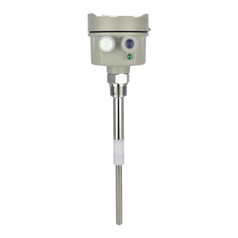
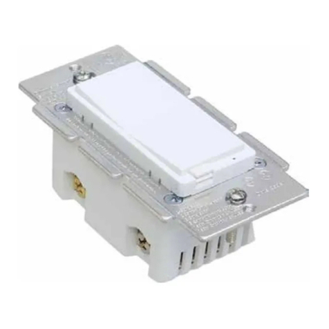
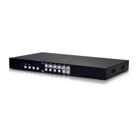
FineTek SA27 User manual

SA27(SAX10□7C)Capacitance Level Switch
Operation Manual
PANEL FUNCTION
SA27 UL Type
※When there are materials or mixtures with multiple characteristics such as high/low dielectric and
conductive haracteristics simultaneously (for example; silica sand in the glass industry, etc), it must be
tested on the site first, to etermine whether the sensor is suitable or not. If there still exists measuring
problems, we suggest using our uning Fork Level Switch (SC) or Rotary Paddle Level Switch (SE).
CONTACT & LED INDICATOR
SPECIAL CONDITIONS FOR SAFE USE OF PRODUCTS
PRECAUTIONS FOR RRODUCT USE
1. LED off when no contact or empty tank.
2. LED on when contact or full tank.
NEPSI Ex d/ia IIC T3~T6 Gb/Ga
Ex tD A21 iaD 20 IP65 T85 C~T200 C
FSH
FSL
Relay
Output
Operation
Mode
Power
failure
N.C.
N.O.
N.C.
N.O.
N.C.
N.O.
N.C.
N.C.
N.O.
COM.
COM.
COM.
COM. N.O.
0VO/P
0VO/P
0VO/P
0VO/PCOM.
LED
Indicator
3-Wire
PNP Output
4-Wire
NPN/PNP Output
3-Wire
NPN Output
red
red
red
red
red
0VO/P
O/P24Vdc
O/P24Vdc
O/P24Vdc
O/P24Vdc
O/P24Vdc
N.O.COM
N.O.COM
N.O.COM
N.O.COM
N.O.
COM
:
:
:
:
:
:
:
Power supply
Output terminal
Coarse calibration
1
2
3
4
5
6
7
Delay time adjustment
Fail-Safe protection adjustment
Sensitivity adjustment
Material indicator
FSHFSL
SENSITIVITY ADJ
SIGNAL
NO C OM NC N L
AC100~240V
SE RIES No.
SE NS IT VIT Y - No.
COAR SE TIM E D ELAY
H
90
80
70
30
60
50
40
20
10
L
+
1.The user should contact the manufacturer directly if detailed information regarding the product is
required.
2.If the product sensor bar is made of or coated with non-metallic materials, specific measures should
be taken to prevent the danger of static electrical explosion.
The safety parameters of the electrostatic capacitance level
switch are listed below:
Open the product only after the power supply is cut off.
The cable entry port must be equipped with a cable entry device or a plug. The component must be
explosion-proof certified according to GB3836.1-2010(IEC 60079-0:2007),andGB3836.2-2010(IEC
60079-1:2007) The explosion-proof type is IIC Gb or Ex db IIC, and connection type is 1/2NPT. The
minimum number of clamps is 6. The installation and use of the cable entry device or the plugging
device must comply with the requirements as stated in the instruction manual. Ensure that the
cover’s protection level reaches IP65, and that it meets the requirements of GB4208-2008(IEC
60529:2001) standard.
The user should keep the product’s surface cover clean to prevent dust from accumulating. Do not
use methods such as blowing with compressed air to prevent dust clouds from raising and forming.
The user should not replace the product parts by himself. Contact the product manufacturer to
resolve any operational problems and prevent damage.
The relation between the temperature group and medium temperature range is as follows (refer to
Figure 1).
Installation, use and maintenance of the product should comply with the instructions found in the
product manual and the following standards:
●
●
●
●
●
●
●
Power supply : maximum voltage Um : 250V
Supply voltage / Contact rating :
110~220Vac±10% ,24Vdc±20%
Power consumption : 2W
Contact output : maximum voltage Um : 250V
Relay (SPDT) : 5A / 250 Vac, 5A /28 Vdc
Transistor (three-wire PNP or NPN) : 400mA/24Vdc±20%
Transistor (four-wire PNP or NPN) : 400mA/60Vdc
2.
3.
4.
5.
6.
7.
1.
(Figure1)
Normal
Temperature
Acid & Alkali
Resistant Type
High
Temperature Type
Type Temperature
Group
Medium
Temperature(C)
T6
T5
T6/T5/T4/T3
T4/T3
T5
T6
T3
T4
-20~+80
-20~+80
-20~+95
-20~+130
-20~+195
-20~+80
-20~+95
-20~+120
GB3836.13-1997(IEC60079-19:1993) “Electrical Equipment for Explosive Gaseous Atmosphere
Part 13: Repair of Electrical Equipment for Explosive Air Pressure”.
GB3836.15-2000 (IEC 60079-14:1996) “Electrical Equipment for Explosive Gaseous Atmosphere
Part 15: Electrical Installation in Hazardous Locations (except Coal Mines)”.
GB3836.16-2006(IEC 60079-17:2002) “Explosive Electrical Equipment for Gaseous Environment
Part 16: Inspection and Maintenance of Electrical Installations (except coal mines)”.
GB15577-2007"Dust Explosion Safety Precautions”.
GB12476.2-2006(IEC 61241-14:2004)"Electrical Equipment for Combustible Dust Environment Part
1: Electrical Equipment Protected by Covers”.
GB50257-1996“Electrical Equipment Installation and Engineering in an Explosive and Fire
Hazardous Environment”.
–
–
–
–
–
–

CAUTION FOR WIRING
DELAY TIME SET UP
The default Delay Time setting is 0 second. When probe contacts with material, LED indicator is
turned on and relay or PNP/NPN output will be activitated. Turn the "Delay Time Adjustment" button
clockwise to set up delay time. After delay time is set, when probe contacts with material, LED is
turned on but the relay or PNP/NPN output will not be generated immediately until delay time is up.
Delay time function is applicable for liquid tanks with agitator, or solid tanks which the medium will
have sudden impact or contact with probe.
COM NO 0V 24V
24 Vdc
Fuse
*Fuse:400mA
*Vdc:MAX.60Vdc
Load
Vdc
0V
SA2 7□A SA2 7□F
SA2 7□B SA2 7□C SA27□E
O/P 24V
24Vdc
Load
0V0V
O/P
24Vdc
Load
Fuse
24V 0V0V
COM NO
24 Vdc
Fuse
*Fuse:400mA
*Vdc:MAX.60Vdc
Load
Vdc
24V 0V0V
NO C OM 0V 110V
110 Vac 220 Vac
Fuse
NC
Fuse
220V NO C OM 0V 110VNC 220V
24 Vdc
NO C OM 0VNC 0V24V
(NC) (NC)
INSTALLATION
200
300mm
A
A
A
B
B
B
α
L >30mm L
25mm Max.
100
300mm
300mm 20
overflowed
For SA27 Plate Model installation,
thickness including tank wall &
connection flange must be less
than 25mm to advoid false action.
For top mounting, angle of repose
must be considered when installation.
SA27 Wire Probe Model must be
installed min. 300mm from tank wall.
SA27 Plate Model is applicable for
bottom mounting.
It's recommended to install the
switch away from material inlet to
avoid damage. If switch must be
installed near inlet area, a
protective cover must be placed
200mm on top of the switch.
When multiple switches are
installed, keep at least 300mm
distance for each switch.
Cable entry must face down firmly
locked to avoid rain damage.
Top mounting is recommended
for medium with poor flowability
to avoid medium build up.
Switches with delay time function
is recommended for tank with
agitator to advoid false action.
Connecting
Pipe
GB3836.13-1997(IEC60079-19:1993) “Electrical Equipment for Explosive Gaseous Atmosphere
Part 13: Repair of Electrical Equipment for Explosive Air Pressure”.
GB3836.15-2000 (IEC 60079-14:1996) “Electrical Equipment for Explosive Gaseous Atmosphere
Part 15: Electrical Installation in Hazardous Locations (except Coal Mines)”.
GB3836.16-2006(IEC 60079-17:2002) “Explosive Electrical Equipment for Gaseous Environment
Part 16: Inspection and Maintenance of Electrical Installations (except coal mines)”.
GB15577-2007"Dust Explosion Safety Precautions”.
GB12476.2-2006(IEC 61241-14:2004)"Electrical Equipment for Combustible Dust Environment Part
1: Electrical Equipment Protected by Covers”.
GB50257-1996“Electrical Equipment Installation and Engineering in an Explosive and Fire
Hazardous Environment”.
SA27 Euro Type
SA27 UL Type
SA2 7□M SA2 7□N
SA2 7□QSA2 7□P
NO COM N
10 0~
24 0V
NC NO COM N C
O/P
L0V 24V
0V 24V 0V 24VO/P
AC
The insulation part must be 30cm
inside the tank at least to ensure
sensitivity is adjustable and to
avoid false action when medium
build up.
Be cautious with installation
location. Angle of repose
must be considered if inlet is
not located in center top of the
tank.
Fuse
Fuse Fuse
*Fuse:400mA *Fuse:400mA
*Fuse:400mA*Fuse:400mA
24Vdc 24Vdc
24Vdc
Load Load
Fuse Fuse
Fuse
100~240V

CALIBRATION (ROTARY KNOB)
MAINTENANCE & TROUBLE SHOOTING
INITIAL CALIBRATION
1. After installation with power supply, make sure no material within 300 mm around the probe.
2. Turn the "SENSITIVITY" to the "H" position (Figure 2).
3. Using flat-head screwdriver to turn "Coarse" clockwisely for adjustment until LED indicator is on.
4. Turn the knob clockwise from H position to 90% position about 1/2 circle (95% position) until LED
indicator shut off (Figure 3). Then, Initial calibration is complete. After that, please continue to next
step "SENSITIVITY ADJUSTMENT".
SENSITIVITY ADJUSTMENT
1. Make sure the "Indicator" sign does not light up, when the medium does not contact with the probe,
and vice versa, when the medium contacts or covers the probe, then the "Indicator" sign lights up.
2. Gradually, adjust the capacitance value (turn the knob clockwise to the "L" direction) until "Indicator"
light turns off.
3. Record the turning angle from "Indicator" sign lights up status to turn off status, then reset "SENSI
TIVITY ADJ" by turning the knob counterclockwise back for half of the recorded turning angle.
4. Based on the previous experience, 70% (Figure 4) adjustment position can be used to most of
mediums (Need to do INITIAL CALIBRATION first).
H
90
80
70
30
60
50
40
20
10
L
H
90
80
70
30
60
50
40
20
10
L
H
90
80
70
30
60
50
40
20
10
L
Figure 3
Figure 2 Figure 4
Circumstance Possibility Cause Trouble Shooting
Water get into
housing
Enclosure is not firmly locked Lock the enclosure firmly
Seal ring aged & failed Replace seal ring
Cable entry is not firmly locked Lock the cable entry firmly
Cable entry does not face down Turn the cable entry & face down
Cable wire does not connected
downward Connect the cable downward
Diameter of cable wire does not fit Replace cable with diameter 8mm~10mm
Sensivity Adjustment knob
is activated by mistake
False wiring of power & signal cable
Circuit damaged by EMI
Dielectric constant of medium
is too small.
Humidity inside tank is over limit
Probe contacts with tank wall
Re-adjust sensivity
Re-wiring according to wiring guide
Replace with anti-static model
Contact your local business representative.
Replace probe with coating
Re-install and avoid grounding
Circuit damaged by EMI
Dielectric constant is over limit
Replace with anti-static model
Contact your local business representative.
Wiring terminals are loose
Process connection is not
firmly locked
Lock screw bolt firmly
Lock thread or flange firmly
Short-circuit due to aging
Abnormal of supply voltage
Revise external layout
Restore power supply
Level up & down but
switch / relay no response
Level up & down but
switch on/off
continuously
non-stop or relay
can't be reset
Loose structure due to vibration Replace with remote model
Unstable switch signal.
Inspection / Evidence
Enclosure is loose
Seal ring aged
Cable entry is not firmly locked
Cable entry faces up
Cable wire is connected upward
Cable wire is loose
Position of Sensivity Adjustment
knob is abnormal
False wiring of power & signal cable
Dry powder or high speed frictioin
Continuous action when
coarse or fine adjustment
Probe with water or dew
Probe contacts with tank wall
Dry powder or high speed frictioin
Continuous action when
coarse or fine adjustment
Loose screw bolt
Loose thread
Idle loop, resistance abnormal
Supply voltage over limit
Obvious vibration environment
08-SA27-B10-EM,03/08/2023
Tel: 886-2-22696789 Fax: 886-2-22686682
Em a il: in f o @ f in e -t e k. co m h t t p : / / w w w. f in e - t e k. co m
No.16, Tzuchiang St., Tucheng Industrial Park, New Taipei City 23678, Taiwan.
F i n e Te k C o L t d. , .
Other FineTek Switch manuals
Popular Switch manuals by other brands

TYAN
TYAN FT70-B7100 Service engineer's manual

ANTAIRA
ANTAIRA LMX-1802G-M12-10G-SFP-67-110 Series Quick installation guide
Siemens
Siemens RUGGEDCOM RSG2100 installation manual

Rextron
Rextron KAG104 user guide
Thermo Ramsey
Thermo Ramsey PRO-LINE 20-35U instruction manual
Larson Electronics
Larson Electronics EPCS-PB10-1XMPB-3PSW instruction manual
