FineTek SIS User manual


2
Contents
1. READING LABELS ..........................................................................................3
2. PRODUCT WARRANTY...................................................................................4
2.1 New Product Warranty..............................................................................4
2.2 Repair Warranty........................................................................................4
2.3 Service Network......................................................................................5
3. PRODUCT INSPECTION..................................................................................6
3.1 Item Check................................................................................................6
3.2 Safety Check.............................................................................................6
4. PRODUCT FEATURES ....................................................................................6
5. SCOPE OF APPLICATION...............................................................................7
6. AMBIENT CONDITIONS...................................................................................8
7. WORKING PRINCIPLE ....................................................................................9
7.1 Output Status...........................................................................................9
8. TECHNICAL PERFORMANCE.......................................................................10
8.1 Specifications..........................................................................................10
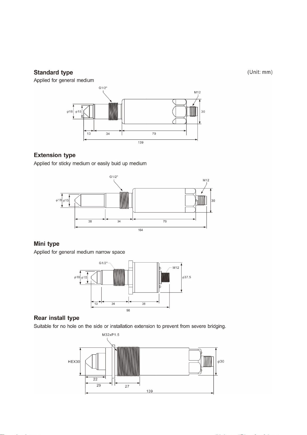
9. EXTERNAL DIMENSIONS .............................................................................13
9.1 Dimensions.............................................................................................13
10. INSTALLATION ............................................................................................14
10.1 Installation Environment........................................................................14
10.2 Installation Process...............................................................................15
10.3 Installation Examples............................................................................17
10.4 Grounding instructions for dust-explosion zone....................................18
11. WIRING INSTRUCTIONS .............................................................................19
11.1 Simulation output test ...........................................................................20
11.2 M12 cable connector for dust-explosion zone.......................................20
12. DAILY MAINTENANCE AND HANDLING....................................................21
12.1 Euipment cleaning for dust-explosion zone ..........................................21
13. SIMPLE TROUBLESHOOTING....................................................................22
14. LIST OF APPLICABLE MEDIA ....................................................................23

3
1. Reading Labels
Thanks for purchasing FineTek’s Product. This operation manual describes the product
features, working principles, operation and maintenance methods. It makes the user fully
understand how to use the product correctly, so as to prevent dangerous situations such as
device damage or operator injury.
Please read this operation manual completely and carefully before using the product.
Please contact the company if this operation manual can’t satisfy your demands.
The content of the operation manual is updated based on the version upgrade, which
will be uploaded to the website for the user to access.
Please don’t disassemble or repair the product on your own, as this will make you
disqualified from availing of the warranty service. Please send the product back to the
company for repair and calibration, or just contact the company.
Explanation of warning signs:
Danger→ It indicates that wrong operation will cause death or major disasters.
Note→ It indicates that wrong operation will cause injury and device damage to
some extent.
Electric shock→ It warns of possible electric shock.
Fire→ It warns of possible fire.
Prohibited→ It indicates the prohibited wrong behavior.

4
2. Product Warranty
2.1 New Product Warranty
We don’t charge for the inspection, part/s and repair for the product of the company
that has a defect within 12 months from the delivery date and meets the warranty
terms.
If the product defect is not due to human error during its transportation, user may
change to a new unit from the company within 7 days from delivery date.
When the product needs to be sent back to the factory for repair, please send the whole
set, and don’t disassemble the parts. Moreover, please be sure it is completely packed
to avoid damage and causing more loss and defect during the transportation.
The warranty is not available for causes that fall under the following circumstances, for
which the company shall charge for the inspection, part/s and repair according to the
actual condition:
The product or its parts are beyond the warranty period.
Fault or damage is caused by not following the instruction and use environment
described on the operation manual.
The product damage is caused by a force majeure factor (natural disasters, floods,
fire, earthquakes, lightning, typhoon, etc.), human destruction (scratches, dropping,
latch broken, tapping, cracks and punching), human error (using improper voltage,
high-humidity, water leakage, stain, corrosion, loss, improper storage, etc.) and
other abnormal factors.
The damage is caused by the customer or the 3rd party through the installation,
addition, expansion, modification and repair of parts not authorized or certified by
the company.
The volume label information is wrong or unclear, so the product serial number
can’t be confirmed.
2.2 Repair Warranty
A 6-month warranty service is provided for the repaired part of the product, during
which the same product can be repaired free of charge in case of the same fault.

5
2.3 Service Network
Company
Address
Telephon
Fax
Taipei
Headquarters
(Taiwan)
No.16, Tzuchiang St., Tucheng
Industrial Park, New Taipei City
23678
+886 2 2269 6789
+886 2 2268 6682
Taichung
Sales office
(Taiwan)
+886 4 2465 2820
+886 4 2463 9926
Kaohsiung
Sales office
(Taiwan)
+886 7 333 6968
+886 7 536 8758
Fine automation
Co., Ltd.
(China)
No. 451, Duhui Road, Zhuanqiao
Township, Minhang District,
Shanghai City 201109
+86 021 64907260
+86 021 6490 7276
FineTek Pte Ltd.
(Singapore Branch)
37 Kaki Bukit Place, Level 4
Singapore 416215
+65 6452 6340
+65 6734 1878
FineTek GmbH
(Germany Branch)
Bei den Kämpen 26
21220 Seevetal-Ramelsloh,
Germany
+49 (0) 4185 8083 12
+49 (0) 4185 8083 80
FineTek Co., Ltd.
(Indonesia Branch)
PERGUDANGAN TUNAS BITUNG
JL. Raya Serang KM. 13,8, Blok C3
No. 12&15, Bitung Cikupa,
Tangerang 15710
+62 (21) 2923 1688

6
3. Product Inspection
3.1 Item Check
Sensor (1)
Operation manual (1)
3.2 Safety Check
Before unpacking, check the packaging for deformation or damage, and take photos to
be used as evidence.
After unpacking, checks the contents for deformation, damage or any quality problems,
and take photos to be used as evidence.
After unpacking, check whether the contents match your order and whether the quantity
is correct immediately.
In any case described above, please contact us within 7 days (attach photos).
Otherwise, free replacements or repairs will not be provided.
4. Product Features
Easy to install due to the standard connector. Protection rating IP67/IP68/IP69K.
The lightweight and compact design make it easy to carry and enable for quick
installation even in narrow spaces or difficult situations.
Surface roughness (Ra) can be customized according to customer needs for chemical
pharmaceutical and food processing industry applications.
The magnetic test action function allows immediate inspection of the wiring and device
proper operation.
Strong and durable stainless steel enclosure.
LED indicators provide field device status.
With overcurrent protection, the output would be immediately turned off when the
output circuit current is overloaded.
Can be applied to CIP and SIP environments.
Unaffected by foam and viscous medium.
Suitable for single point level detection and pump idling protection for liquid, viscous
medium, and powder medium in containers and pipelines.
2 output units can be set individually to help detect 2 different media (such as separate
layers, foam or oil + water).
Acquired NEPSI dust Explosion-proof Certificate, Ex tD A20 IP67 T85℃T200 100℃.

7
5. Scope of Application
Scope
The product is designed based on food grade structure and materials, ideal for food
and health areas.
Suitable for level detection of water-based medium, oil-based medium, powder or
sticky material as a switch output.
Can be used for liquid with separate layers (such as bubbles) and two-level or interface
detection (such as oil + water).
Can be used for almost all media; low specific gravity, low dielectric, non-conductive
media can all work properly.
Limitations
Not suitable for bulk solid or rough material (such as quartz sand).
Not suitable for highly corrosive media (strong acids and strong alkaline). Please check
the compatibility with the product material first.
Media with separate layers of different natures (such as oil on the water surface)
must be checked in advance.
Only explosion-proof type specifications can be used in dust explosion-proof
hazardous environments
The sensor must be installed with the exclusive “Thread adapter” and its sealing
ring to ensure proper sealing
The special requirement used in the dust-explosion environment
If the connection is the metal tank or pipe, it must be grounded so the danger of static
electricity generated by friction or impact can be avoided.
If the connection is not the metal tank or pipe, the sensor must be installed with the
exclusive “Thread adapter” and use “thread adapter” to complete the grounding.
The cross-sectional area of the grounding wire must be greater than 4mm2
(>11AWG). (Please refer to the installation instructions above)

8
6. Ambient Conditions
Normal type (Standard type / Extension type / Mini type)
Storage temperature: -40°C ~ 85°C (-40°F ~ 185°F)
Ambient temperature:-40°C ~ 85°C (-40°F ~ 185°F)
Medium temperature: Continuous; max.100°C
@ ambient temperature -40°C~85°C (-40°F~185°F)
Short time(1hr); max.150°C (Mini type: max.135°C)
@ ambient temperature -40°C~60°C (-40°F~140°F)
Power supply: 18 VDC ~ 30 VDC
Output load current: Max. 100 mA
Rear install type
Storage temperature: -40°C~85°C (-40°F~185°F)
Ambient temperature: -40°C~80°C (-40°F~176°F)
Medium temperature: -40°C~80°C (-40°F~176°F)
Power supply: 18 VDC~30 VDC
Output load current: Max, 100 mA
Explosion-proof type
Storage temperature: -20°C ~ 85°C(-4°F ~ 185°F)
Ambient temperature: -20°C ~ 70°C(-4°F ~ 158°F)
Medium temperature: Max, 100°C @ Ambient temperature-20°C ~ 70°C(-4°F ~ 158°F)
Power supply: 18 VDC ~ 30 VDC
Output load current: Max. 50 mA

9
7. Working Principle
Working principle of this sensor is based on the frequency sweep
technology. The sensor tip will send out electric field signal, and
different resonance frequency is created according to different
medium. Thus a switching signal will be triggered if the sensor is
covered with material..
7.1 Output Status
The following table shows the corresponding output status for the factory default
values (group 1 output NO, group 2 output NC):
*IL represents load start
LED locations

10
8. Technical Performance
8.1 Specifications
Normal type
Rear install type
Explosion
proof type
Scope (optional)
Water-based media, oil-based media, powder
media, dual-level media (such as oil+water),
fluid with separation layer (such as bubbles)
Powder media
Storage
temperature
-40°C ~ 85°C (-40°F ~ 185°F)
Ambient
temperature
-40°C ~ 85°C
(-40°F ~ 185°F)
-40°C ~ 80°C
(-40°F ~ 176°F)
-20°C ~ 70°C
(-4°F ~ 158°F)
Operating
temperature
Continuous: max.100°C
while ambient temp.
-40°C~85°C(-40°F~185°F)
Short time(1hr):
max.150°C
(Mini type: max.135°C)
while ambient temp.
-40°C~60°C(-40°F~140°F)
-40°C ~ 80°C
(-40°F ~ 176°F)
Max.100°C while
ambient temp.
-20°C ~ 70°C
(-4°F ~ 158°F)
Power Supply
18 VDC ~ 30 VDC
Current
consumption
Max. 50 mA
Overvoltage
protection
Class II
Reverse
protection
Yes
Output type
(optional)
DC PNP/NPN
Number of
outputs
2 switch outputs
Switch type
(optional)
Group 1 output NO, Group 2 output NC
Output load
current
Max. 100 mA
Max. 50 mA
Output voltage
drop
Max. 2.5 VDC

11
Short circuit
protection
Short pulse
Overload
protection
Yes
Switch delay
(optional)
Standard < 1 second (max. 60 seconds)
Electrical
connection
M12 4PIN connector socket
Wetted part
material
(optional)
SUS304, SUS316, SUS316L
Operating
pressure
-1 ~ 40 bar
Process
connection
G 1/2”
M32*P1.5
G 1/2”
Probe
material/surface
roughness
PEEK/Ra<0.8
PEEK-
1000/Ra<0.8
Enclosure
protection rating
IP67/IP68/IP69K (IP68 up to 1 meter underwater for 30 days)
Status indication
Switch active LED yellow
Switch reset LED green
Simulation
output test
(Not available
for mini type)
Magnetic test (lean a magnet close to the + sing for 2 seconds,
there will be switching output)
Communication
mode
"IO-Link V1.1
Standard
compliance
IEC61000-4-2, IEC61000-4-4, IEC61000-4-11
Explosion-proof
Certificate
N/A
NEPSI Ex tD A20
IP67 T85℃T200
100℃

12
Warning !
1. Only Explosion-proof type can be installed and used in Combustible dust explosion
environment.
2. The sensor must be installed with the exclusive “Thread connector” or “Thread adapter”,
in order to ensure the installation sensor operate normally and avoid leakage.
3. The electrical connection of this device has achieved IP68/IP69K protection grade, so it
must be connected with the corresponding M12 connection cable in order to be installed
properly.
4. Explosion-proof type must be installed with M12 connection cable approved by NEPSI, in
order to use it in the explosion environment (please refer to chapterAccessories - Thread
Connector/ ADAPTOR").
13
9. External Dimensions
9.1 Dimensions
14
10. Installation
Before installing and unloading the product, make sure that the device is
not suffered to any pressure and that the material inside the pipe or
container does not have leakage. Pay attention to the potential hazards
relevant to the temperature of the device and the media.
10.1 Installation Environment
Suggested to install the product in a metal container or pipe.
When installed in a plastic container, performance degradation or malfunction
may occur due to interference.
Check that the product is working properly via the field test function.
If interference occurs, take appropriate measures (shielding, grounding).
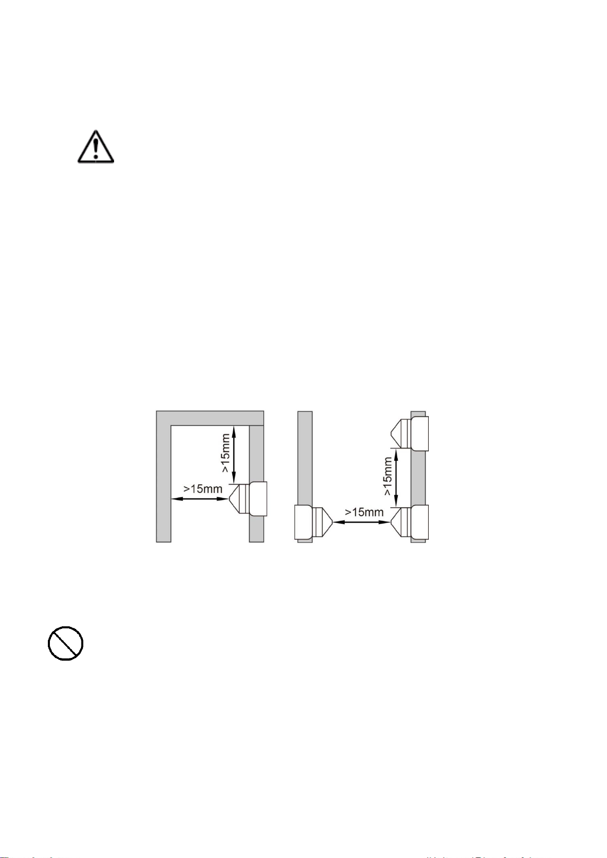
For pipe installation, the pipe size must be bigger than DN25.
Install the sensor at a distance of at least 15mm from the pipe wall, structural
parts, stirrer, and other sensors to prevent errors caused by collision or
interference (as shown below).
The insertion of the sensor should be sufficient to prevent the sediment from
being wrongly considered as the material (especially solid materials). The probe
of the sensor must be completely through the tank wall.
Do not use seal tape. The sensor must be well grounded with the container
or pipe.
The sensor probe must be protected from direct sunlight (UV).
Warning !
In the dust explosion-proof environment, it is forbidden to produce the process of
propagation brush discharge type and brush discharge type. Such as the rapid
movement of dust particles, powder transfer process and spraying process in
electrostatic coating process.
15
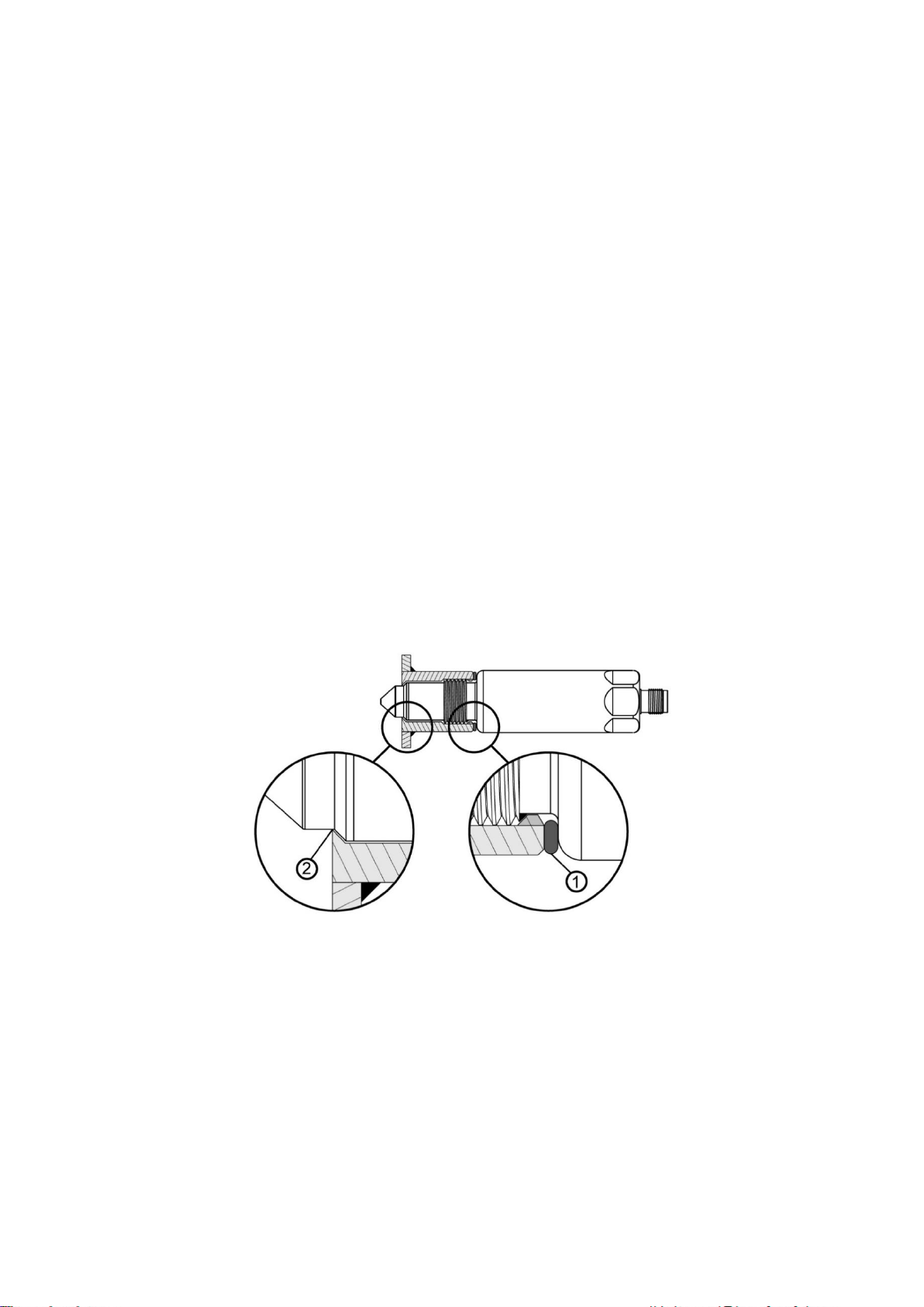
10.2 Installation Process
Make sure that the sealing surface is clean before installation and remove the
protective cover only when installing. If the sealing surface is damaged, replace
the device or adapter sleeve.
Install or weld the adapter sleeve onto the container/pipe. For the welding
operation, please refer to "SISB Welding Adapter / Thread Adaptor Operating
Instructions".
For installation of the tri-clamp, follow the relevant provisions for additional
installation steps.
Attach the seal to the sensor through the thread lock sleeve. The seal must be
correctly positioned and locked. Close the gap between the sensor and the
adapter sleeve end face.
Use the seal supplied with the sensor only. An inappropriate seal may cause
installation errors.
- The seal is too thick:A gap exists between the sensor tip and the adapter
sleeve.
- The seal is too thin: The seal is insufficiently compressed between the
sensor and the adapter sleeve. Leakage may occur.
Normal type
The seal (supplied with the adapter sleeve) is
squeezed
The sealing cone of the adapter sleeve/the sealing
end face of the probe is squeezed
Apply a little grease in the thread to help locking.
Lock the sensor into the adapter sleeve and tighten with a tightening torque
of 20...25 Nm.

16
Rear install type
Auxiliary rod is needed for rear installation, auxiliary rod is not included in the
order (customized order if need)。
When tightening, the sealing ring is not exposed and must be compressed at
least 1/4 wire diameter or more than 0.3mm to ensure the seal, and the
tightening torque is controlled between 20...30 Nm.

17
10.3 Installation Examples
The sensor can be installed as shown below:
Normal type
Tank Diagram Pipeline Diagram
The figure on the left shows an example of container installation, such as for
liquid level detection or as idling protection.
The figure on the right shows an example of pipe installation as liquid level
monitoring.
Attention! For highly viscous medium, the installation location ★in the
figure is only applicable to a certain extent. Residues may be incorrectly
detected as liquid level output.

18
Rear install type
Top-mounted Side-mounted
After installation, please check whether the resistance of the container or
pipe entrance is within the allowable range.
Make sure that the top cable is properly sealed, such as installing and locking
the cable gland.
Cables cannot be routed directly upwards, please go around for a short
distance and then route them upwards to release water.
10.4 Grounding instructions for dust-explosion zone
To prevent dust or flow being generated by friction or impact, this product can
be used in the dust-explosion area. Please confirm the grounding condition in
the installation environment and take proper grounding.
If the connection is the metal tank or pipe, this product is grounded through
“thread adapter” and metal tank or pipe. Please confirm that the installation
environment is grounded to prevent electrostatic charge.
If the connection is not the metal tank or pipe, the sensor must be installed
with the exclusive “Thread adapter" and use “thread adapter” to complete the
grounding.
The probe crosses the material of
the barrel wall and effectively
inhibits bridging.
High/low alarm and to
solve the problem that
no hole in the side.

19
11. Wiring Instructions
Attention! Wiring must be carried out by an electrician.
Make sure you comply with national and international regulations related to
the installation of electrical equipment.
The input power supply must be within the specifications of the product.
Turn off the power before wiring.
Make connections according to the wiring diagram below.
Insert the connector plug into the top socket of the sensor and tighten the nut.
Wiring diagram:
R1 and R2 represent the load of OUT1 and OUT2 respectively.
To protect the sensor from damage in the event of system failure, adding FUSE
0.5A to the power circuit is recommended.
only represents the property. The actual wire color depends on the connector
purchased.
Note: The accuracy and efficiency can not be guaranteed if using NON-FineTek
connector.

20
11.1 Simulation output test
1. Finished the installation and supply the sensor with 18~30Vdc.
2. Lean a magnet close to the + sing for 2 seconds or more, there
will be switching output with corresponding LED light display.
3. Remove the magnet from the + sign, the switching output
and corresponding LED light display will return to
normal status.
11.2 M12 cable connector for dust-explosion zone
Do not open the connector when there is an explosive dust environment.
Please complete the M12 cable installation in the safety area first, and
then complete the on-site installation before providing supply power.
Please use 14mm size open-end wrench to operate with the torque around
1~1.5 Nm (0.1~0.15 kgf.m)..
Use M12 cable type in dust explosion-proof environment which approved by
NEPSI; ADOAH040VAS0005E04, ADOAH043VAS00005E04 (order code;
PC3121231415M011, PC312-1232410501)
Torque: 1.5Nm
Other manuals for SIS
1
Table of contents
Other FineTek Switch manuals


Popular Switch manuals by other brands

Brocade Communications Systems
Brocade Communications Systems VDX 6940 Series datasheet

D-Link
D-Link xStack DXS-3350SR Specifications

SOMFY
SOMFY DECOFLEX 1810897 instructions

TP-Link
TP-Link TL-SG1016D user guide

Cardin Elettronica
Cardin Elettronica SEL Series quick start guide

Leuze electronic
Leuze electronic CSL710-T05-1280.A-M12 Original operating instructions


