9
CONTENTS
Security Features
Security features help protect the information in the terminal from being accessed by
unauthorized individuals.
ADMIN AFFIRM
Register an administrator into the system by enrolling or a password to a user ID. Press
Menu > User Manage > Enroll Admin > Choose enrollment method > Perform enrolment
and Save. After enrolling an administrator, the main menu can only be accessed by the
administrator.
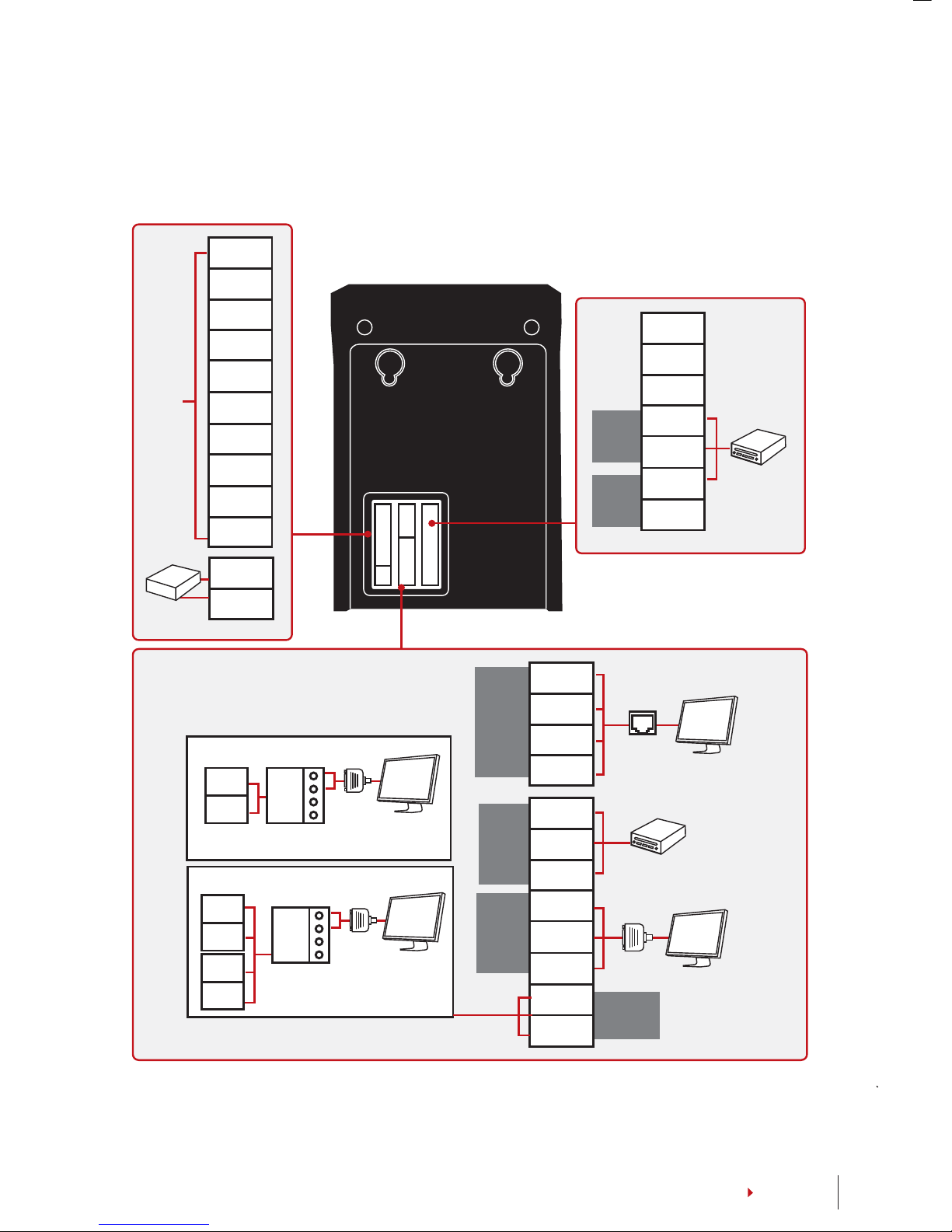
TAMPER SWITCH
The terminals come with a tamper switch located at the rear of the terminals. During
installation, the tamper switch is compressed against the back plate. Any attempt to dis-
mantle the terminal will trigger an alarm and a “System Broken” message will be dis-
played on the panel.
Cleaning Terminal
CLEANING THE BODY
Use a dry cloth to clean the terminal’s body. Do not use any liquids, household cleaners,
aerosol spray, solvents, alcohol, ammonia and abrasive solutions to clean the body of the
terminal because it could damage it.
Restarting and Resetting Terminal
If a feature isn’t functioning as it should, try restarting or resetting the terminals
RESTARTING THE TERMINAL
Push the On/Off button or “reset button” on the terminal to restart the terminal. If you
can’t restart the terminal, or if the problem persists, you might want to reset.
RESETTING THE TERMINAL
Press Menu > Option > System Option > Adv Opt > Reset terminal. Resetting of the termi-
nal will cause all your settings to return to its original factory settings. Make sure that you
have backed up all data before you proceed.