Finnleo NorthStar Series User manual
71-0164 Page 1 4215-139
Rev. 01 09/07/2021
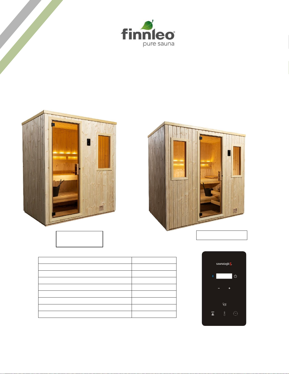
NorthStar Indoor Series Owner’s Manual
NS 46, NS 56, NS 57
with SL2 Control and CB 16-1
and Bluetooth Sound Sytem (Optional)
Precautions Before Use
2
Read Before Installation
2
Room Summary
3
Room Assembly
4
Electrical Installation
9
Sound Bar Installation
13
Interior Installation
15
Control Operation
17
Maintenance and Troubleshooting
19
NS 46, NS 56 Room
(4’ x 6’, 5’ x 6’)
NS 57 Room (5’ x 7’)

71-0164 Page 2 4215-139
Rev. 01 09/07/2021
Read all instructions carefully before installation including instructions packaged separately
with the sauna heater. Please leave all instructions and warranty with the owner.
WARNING: When using electrical sauna heaters and associated sauna products, basic precautions must be
followed, including the following:
1. Grounding is required.
2. No electrical receptacle shall be installed in the sauna room.
3. Be sure rocks are placed in the heater according to the Heater Installation and Operation Instructions.
4. Do not tamper with the door or install a latching or locking system. Malfunction of which may cause
entrapment inside the heated room.
5. Do not block ventilation openings. Vents must be kept free of obstruction so proper airflow is
maintained in the sauna room. Do not stack anything in front of the vents.
WARNING: Prolonged exposure to elevated temperatures is capable of inducing hyperthermia.
Hyperthermia occurs when the internal temperature of the body reaches several degrees above the normal body
temperature of 98.6°F. The symptoms of hyperthermia include an increase in the normal temperature of the
body, dizziness, lethargy, drowsiness, and fainting. The effects of the hyperthermia include failure to perceive
heat, failure to recognize the need to exit the room, unawareness of impending hazard, fetal damage in pregnant
women, physical inability to exit the room and unconsciousness.
WARNING: The use of alcohol, drugs, or medication is capable of greatly increasing the risk of fatal
hyperthermia.
CAUTION FIRE HAZARD: Do not use the sauna room for drying clothes, bathing suits, etc. Do not
hang towels above the heater or place any object, other than the rocks supplied, in the heater. If any darkening
of the wall around the heater is noticed, discontinue sauna use immediately.
ROOM ASSEMBLY
•Each panel is heavy. Be careful to avoid injury when installing, especially the ceiling panels.
•Two adults are required for the installation of sauna room.
•The wall panels are connected with tongue and groove slots which will be installed in the following way:
oWhen setting panels, ensure the tongue lines up into the groove.
oSecure wall panels together with a screw on top of the wall.
oConnect corners of wall panels with screws in the side wall.
71-0164 Page 3 4215-139
Rev. 01 09/07/2021
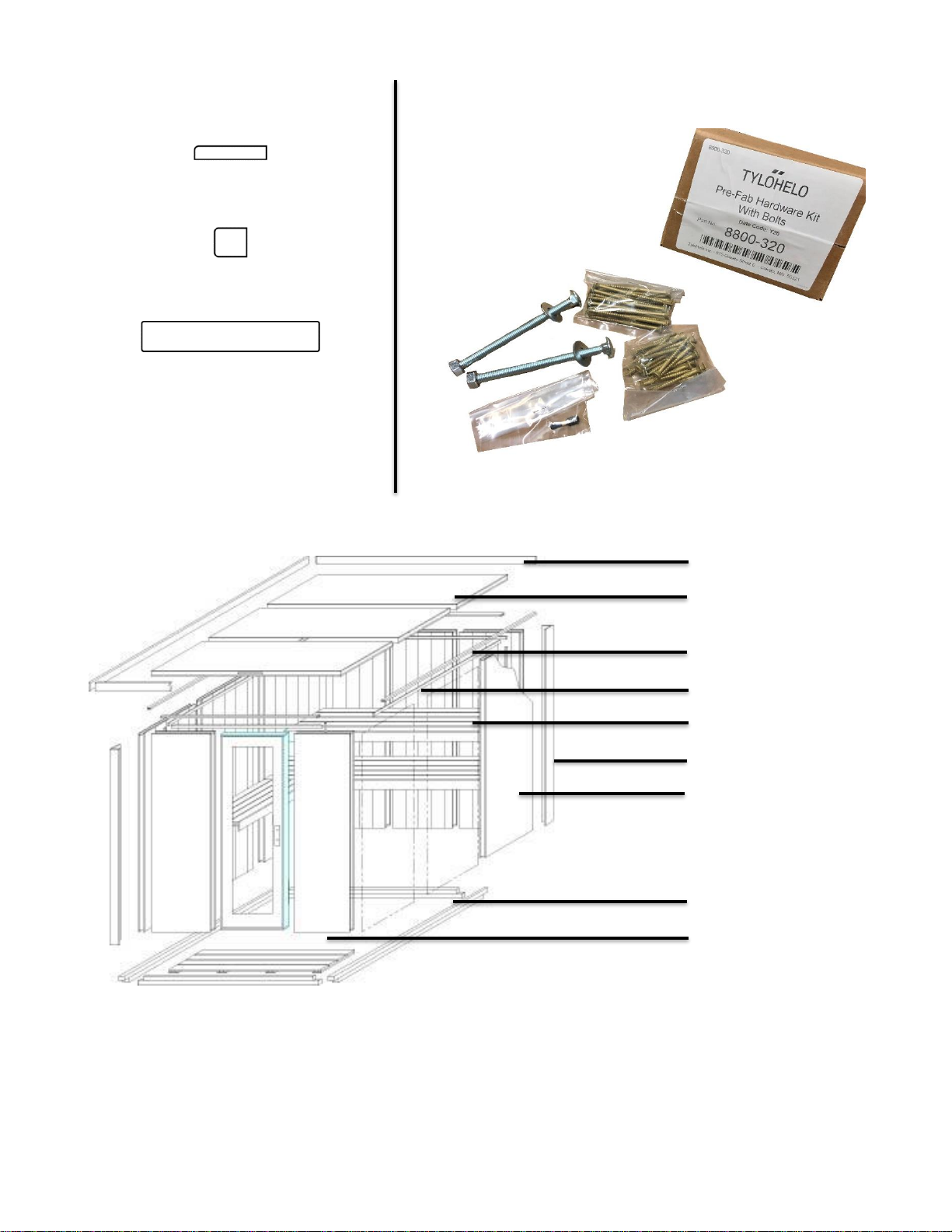
Trim Profiles Hardware Package
Note: Parts depicted in the diagram will differ between models.
Carriage Bolts, Washers,
& Nuts (for saunas with
L-benches)
Torx Bit
9 x 2 Wood Screw
9 x 3 Wood Screw
Window/Door Casing (normally pre-installed)
Inside Cove Molding
Exterior Fascia Trim
Fascia Trim
Ceiling Panel
Top Plate
Interior Cove
Benches
Exterior Corner Trim
Wall Panel
Base Frame / Floor
Duckboard Floor
71-0164 Page 4 4215-139
Rev. 01 09/07/2021
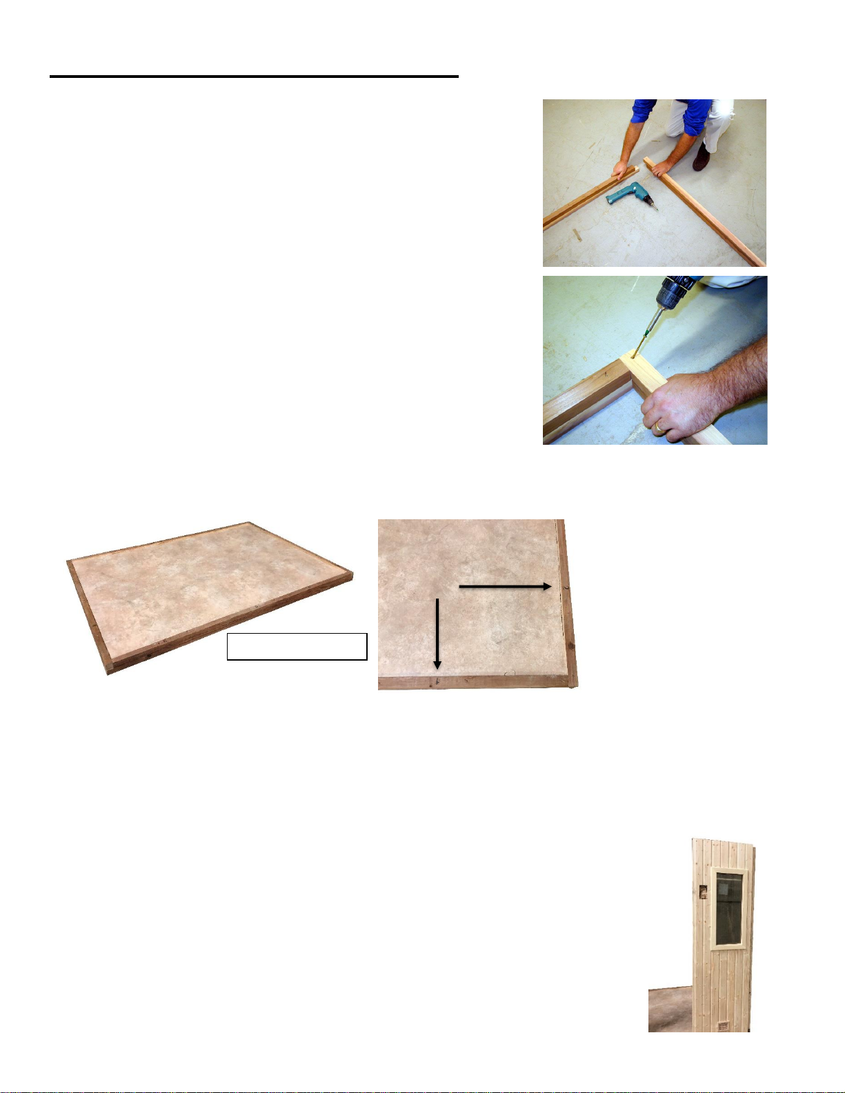
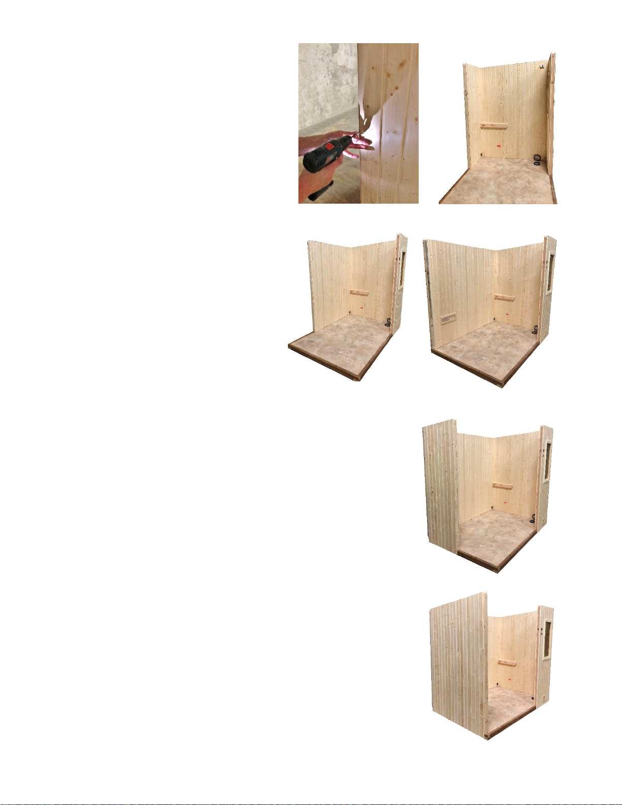
INSTALLATION OF SAUNA ROOM
1. Position the base frame (or optional floor panel) in the desired location on
a level surface.
2. Fasten the corners of the base frame using one 3” screw at each corner in
the predrilled holes.
Note: Predrilled holes are purposely made at an angle.
Note: The base must be level before installing wall and
ceiling panels. If the surface is not level, you may need to
shim the floor panel to get it level.
The base is numbered to correspond with the panels for correct locations. The front right wall panel is labeled #1, the front
panel of the right side wall is labeled #2 and etc…(See picture below)
Note: The 4 x 6 room has a one-piece side wall system, and the and 5 x 6 and 5 x 7 rooms have a two-piece side wall
system. The two-piece system is shown, but the process is the same for the one-piece system.
3. Place the front right corner wall panel (panel 1) on the outer edge of the corresponding floor
panel.
Optional Floor Panel
71-0164 Page 5 4215-139
Rev. 01 09/07/2021
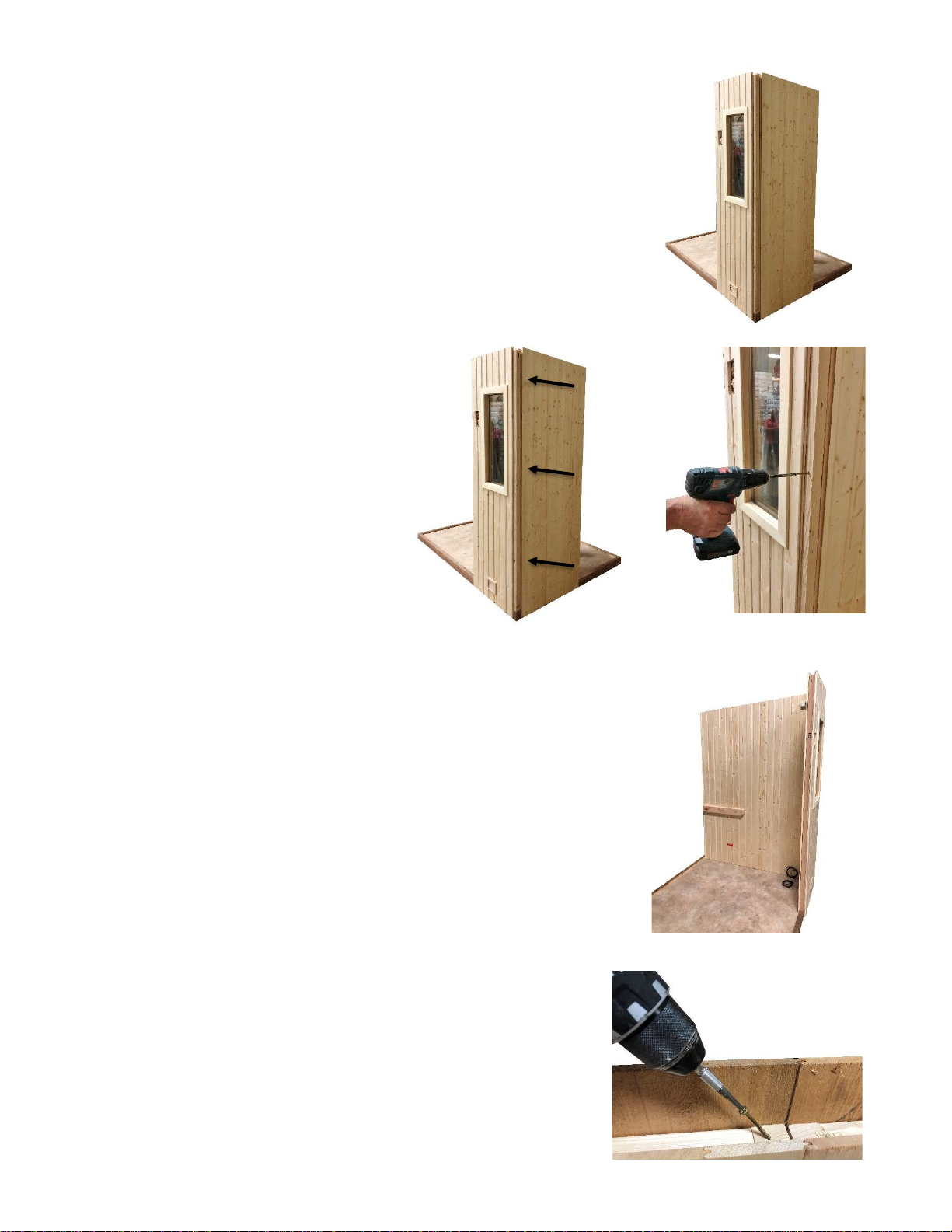
4. Place the front panel of the right wall (panel 2) on the floor and butt it to the front
panel.
5. Secure the right wall to the front wall with
three 3” Torq screws (provided). Install one
screw on the top of the wall, one in the
middle, and one on the bottom. Ensure the
tongue and groove wall boards are tight
together at the interior corner of the sauna and
the corner is flush on the outside edge when
screws are installed.
6. Install the next wall panel of the right wall. Ensure the tongue and groove are
fully engaged between panels.
7. Secure the two wall panels together with a 3” screw where the panels
meet on top. Ensure tongue and groove are fully engaged.
71-0164 Page 6 4215-139
Rev. 01 09/07/2021
8. Install the next panel in the number series. Secure
the side wall to the back wall panel with three 3”
Torq screws. Ensure the tongue and groove are tight
at the interior corner when screws are installed.
9. Install the second and third panels of the back
wall. Repeat step 7 between each back panel.
10. Install the next panel in the number series. Secure to the back wall with three 3”
Torq screws. Ensure the tongue and groove are tight at the interior corner
when screws are installed.
11. Install the next wall panel of the left wall. Repeat step 7 between the wall
panels.
71-0164 Page 7 4215-139
Rev. 01 09/07/2021
12. Install the door panel next to the right front wall panel. Repeat step 7 between
wall panels.
13. Install the remaining wall panel to the door panel. Repeat step 7 between wall
panels.
14. Secure left front wall panel to the left side wall with three 3” Torq screws.
Ensure the tongue and groove are tight at the interior corner when screws are
installed.
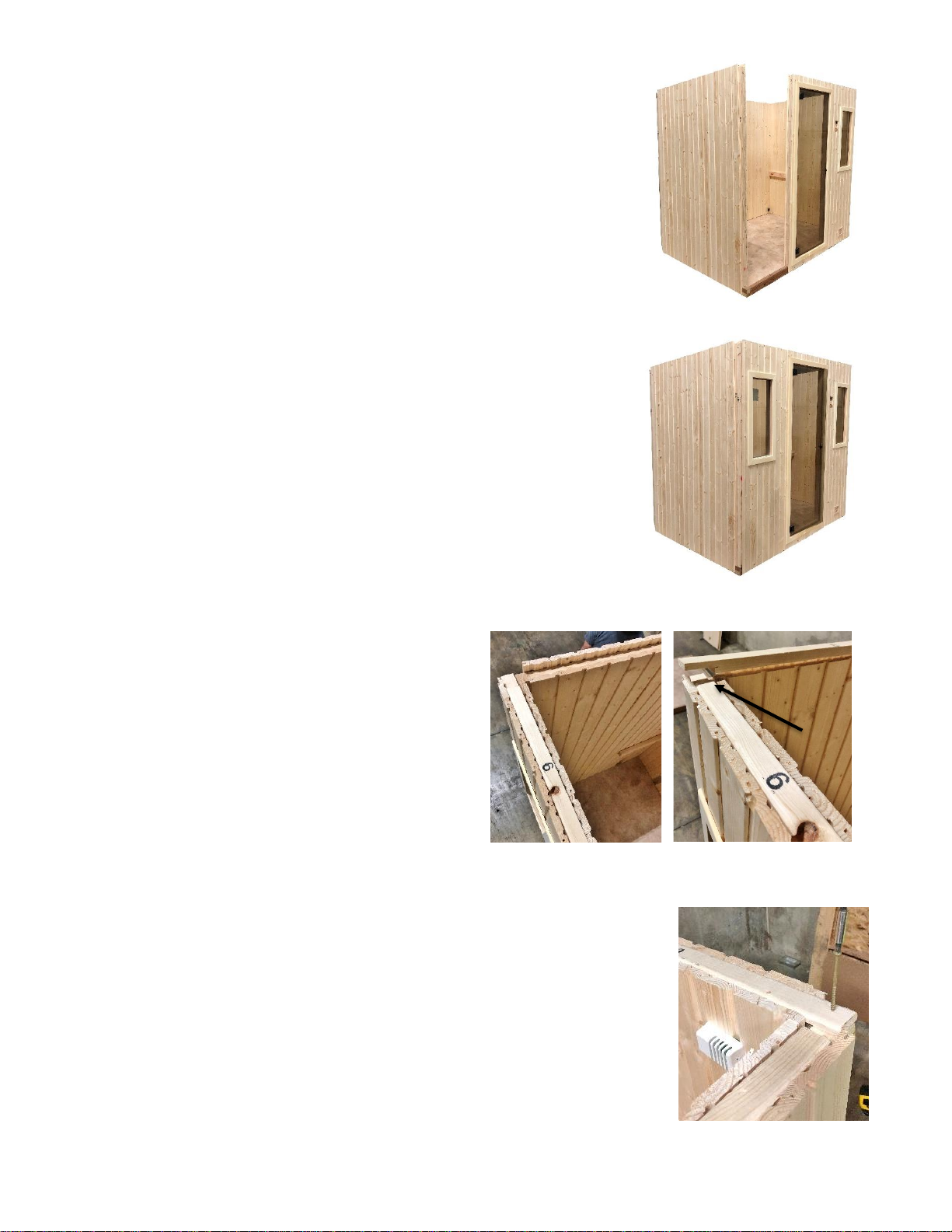
15. Install top plates to the corresponding wall panels on
front and back sides with the notched ends facing up.
Install the left and right side top plates so they fit into the
notches.
Note: Before installing top plates, ensure all panels are
connected together on top and on the corners.
16. Secure top plates using the 2” Torq screws. Install one screw in each corner and one
screw in the center of each wall.
71-0164 Page 8 4215-139
Rev. 01 09/07/2021
17. Install corner caps to each corresponding wall panel using Brad nails or finishing nails (not supplied).
Note: Some woods will twist, which is normal, so installation can be more difficult. See end of manual for suggestions on
how to install a twisted corner cap.
18. Install the lower bench supports
to the right and left side walls
between the pencil marks on red sticker labeled “Lower Bench Support”.
Secure with 3” Torq screws in the provided predrilled holes.
Note: The 4 x 6 and 5 x 6 rooms have a two-panel ceiling and the 5 x 7 room
has a three-panel ceiling.
19. Place the right ceiling panel on the room.
20. Place the left ceiling panel on the room (left and center panels of the NS 57).
Ensure the tongue and groove fully engages.
21. Fasten ceiling panels down to the wall panels using 3” screws.
Note: Ceiling panels are designed ¼” smaller than the opening. Make sure the top
of the sauna walls are square with the ceiling panels.
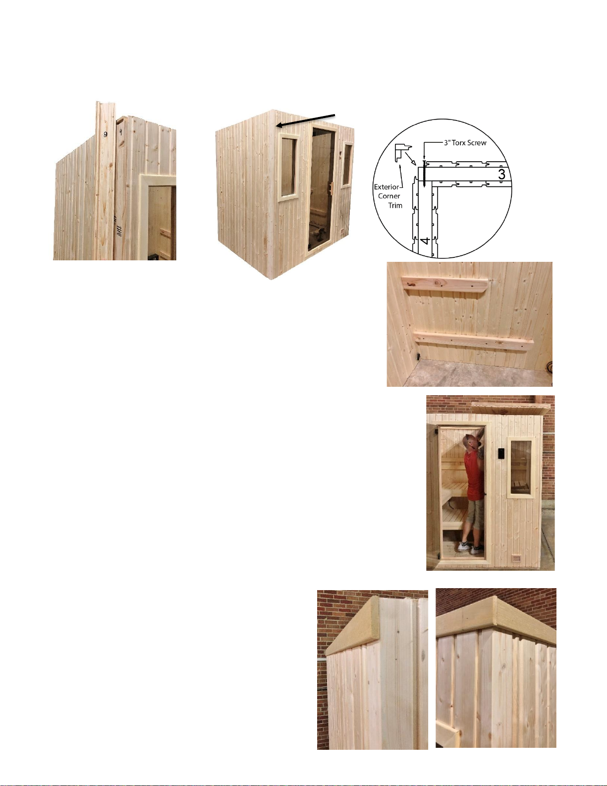
Note: Trim is sent long and needs to be trimmed onsite for proper fit.
22. Nail fascia trim to the exterior back wall so it is flush to the left and right edges of
the wall.
Note: The fascia top should be flush with the top of the
wall panel.
23. Install fascia to the side walls so it is flush to the back
fascia and the edge of the front wall.
24. Install fascia to the front wall so it is flush to the left and
right side fascia.
71-0164 Page 9 4215-139
Rev. 01 09/07/2021
25. Install interior cove to front wall so it lays flush to left and right edges of
the wall.
26. Install cove to back wall so it lays flush to left and right edges of wall.
27. Install cove to left and right side walls so it lays flush to front cove and
back cove.
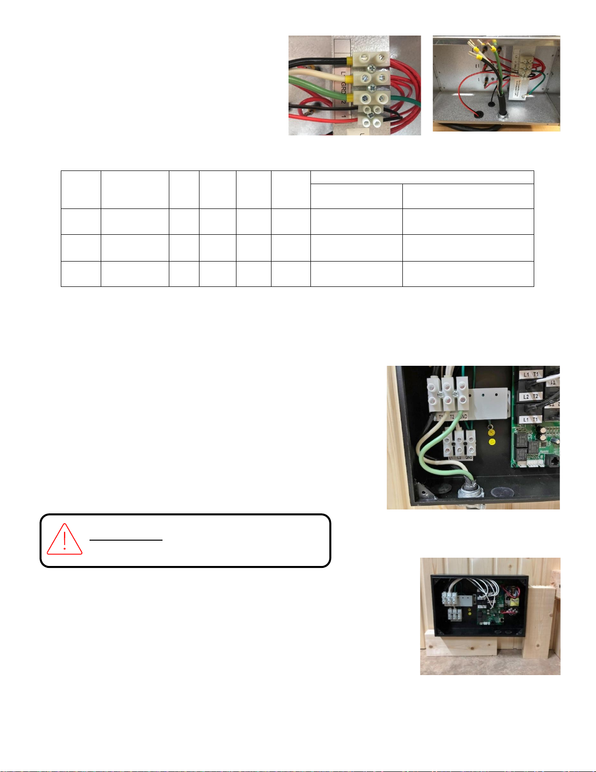
ELECTRICAL / HEATER ASSEMBLY
28. Place CB Box on the floor for easy access. Remove the cover to access
the electrical connections.
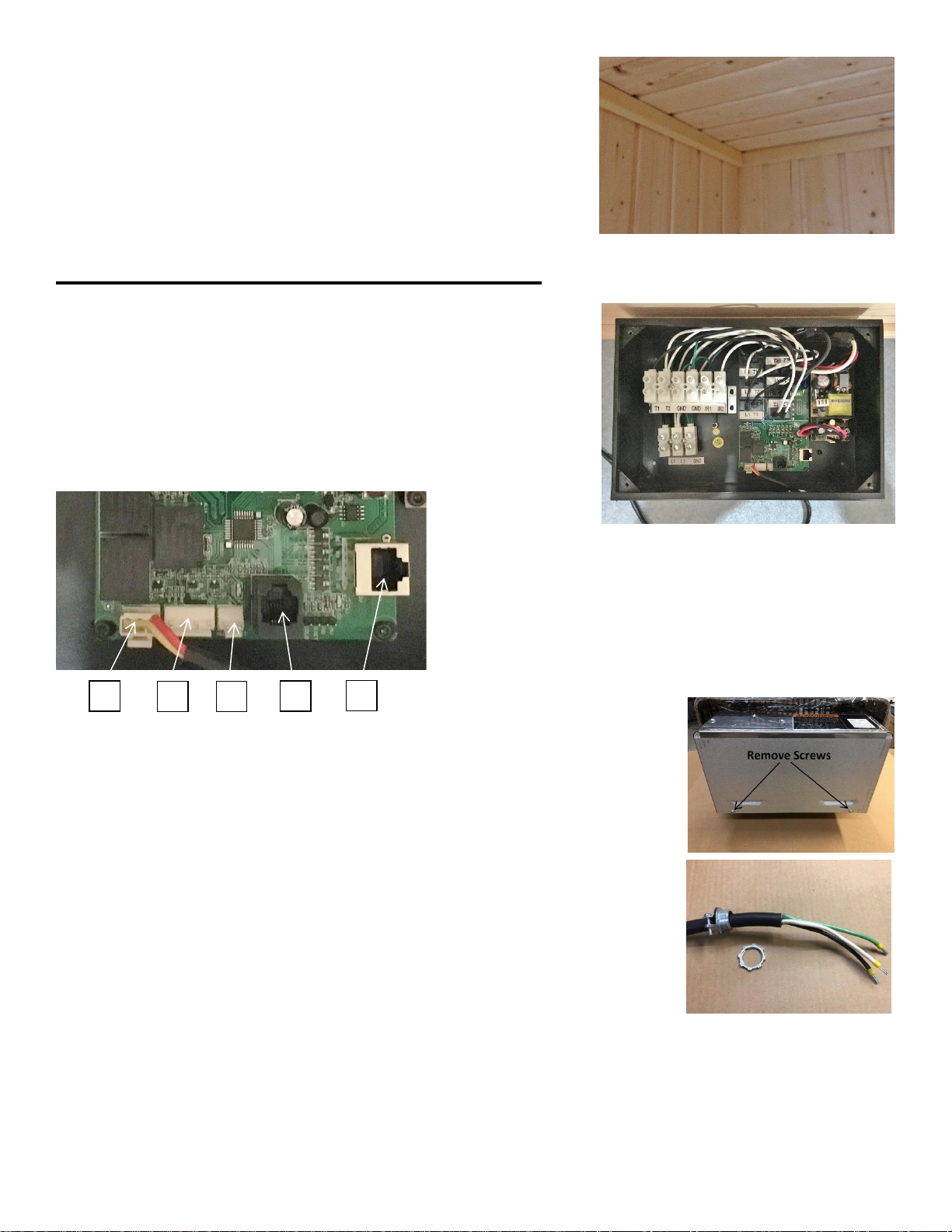
29. Connect all the quick connections into the CB Box
according to the picture and installation manual.
Note: All the low voltage connections have unique connectors.
1- Bluetooth Power (3 pin from Bluetooth sound bar (optional))
2- Room Temp Sensor (4 pin from wall)
3- High Limit (2 pin from heater)
4- Control (RJ 11 from wall)
5- Lights (RJ 45 from wall)
30. Install power cable (provided) to the sauna heater.
31. Lay the heater on its back and remove the two #8 screws that secure the bottom cover
plate (save screws for re-installation).
32. Install the strain relief clamp as shown, about 2.5” from the end of the black rubber
insulation. Remove the retaining nut for later installation in heater. Tighten the two
clamp screws securely so the strain relief does not slide on the cable.
33. Insert the cable into the open hole on the back of the electrical enclosure and secure using the retaining nut from the
first step. Tighten nut to prevent the strain relief from moving.
1
2
3
4
5
71-0164 Page 10 4215-139
Rev. 01 09/07/2021
34. Insert the black, white, and green wires into the
terminal block as shown. Tighten the screws
securely (approximately 18 in/lbs.)
Green = ground
Black = L1 (hot)
White = L2 (hot)
35. Determine power requirements and wire size needed based on the room model.
Room
Sauna
Heater
kW
Phase
VAC
Sauna
Amps
WIRE SIZE
Power Supply to
CB 16-1
CB 16-1 to Traditional
Heater
NS 46
Viki 4.5
4.5
1
240
18.8
2 #10AWG + GR
2 #10AWG + GR
NS 56
Viki 6.0
6.0
1
240
25.0
2 #10AWG + GR
2 #10AWG + GR
NS 57
Viki 6.0
6.0
1
240
25.0
2 #10AWG + GR
2 #10AWG + GR
NOTE: All installation and service to this equipment should be performed by qualified licensed personnel in accordance
with local and national codes.
NOTE: A GFCI (Ground Fault Interrupt Circuit) device is not required by NEC. A GFCI may be installed if required by
local codes but will nuisance trip during use of the product.
CAUTION: Loose wire connections can cause heat damage to wires, terminal
blocks, and other components and may void the warranty.
36. Connect wires from building electrical supply to the lower terminal block
labeled L1, L2, and Gnd. (Building wire is not supplied)
37. Connect wires from the heater to upper terminal block labeled T1, T2, and
Gnd to the sauna heater.
38. Install the CB-16-1 Contactor box to the back wall. Use the two spacing blocks
provided as a guide to find the lower left corner of the box to wood corner trim on
wall.
Note: If the mounting holes of CB box line up with a groove in the wall, move the
box left or right so they line up on a solid portion of the tongue and groove.
WARNING: Final input power should be
performed by a qualified electrician.
71-0164 Page 11 4215-139
Rev. 01 09/07/2021
39. Mount the CB Box to the back wall with the four screws provided in the hardware
pack inside the CB box.
40. After all connections are complete, place cover on CB Box with the four screws
provided.
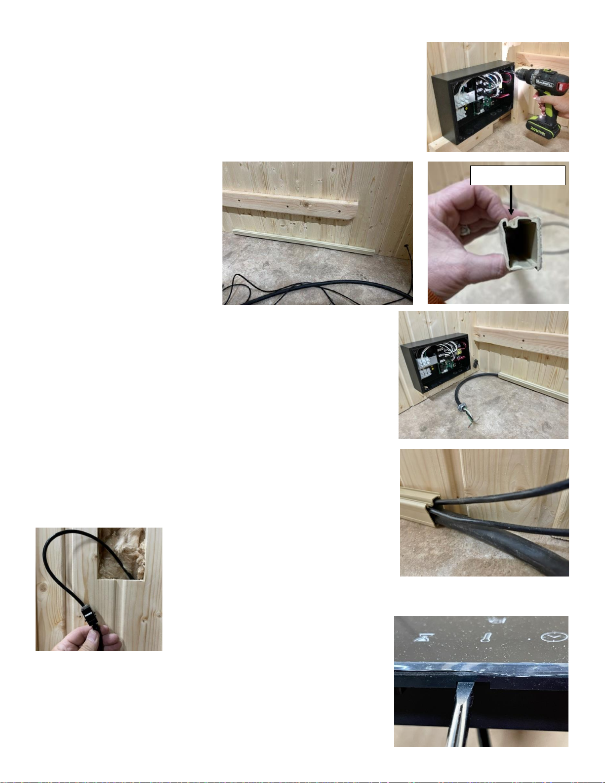
41. Install plastic wire raceway on right side wall. Peel adhesive strip off the back side
of raceway and attach to the wall, flush with the floor and about 12” from the front
of the room. Make sure the open slot is facing up so wires can be inserted.
42. Insert the large black main power cable into the open slot of the wire
raceway.
43. Insert the sensor and control cables into wire raceway, one cable at a time,
and orientate them so they are on top of the large power cable and
positioned towards the back of the raceway.
44. When all the cables are in the raceway, seal the raceway shut by starting at
one end and snapping the “cover” shut as you move towards the opposite
end. If the cover will not close you may need to re-orientate the wires.
45. Connect the control wire from the front wall to the control.
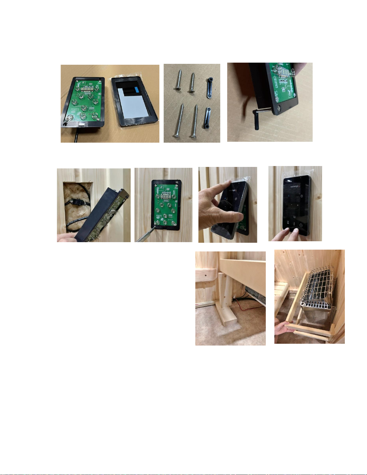
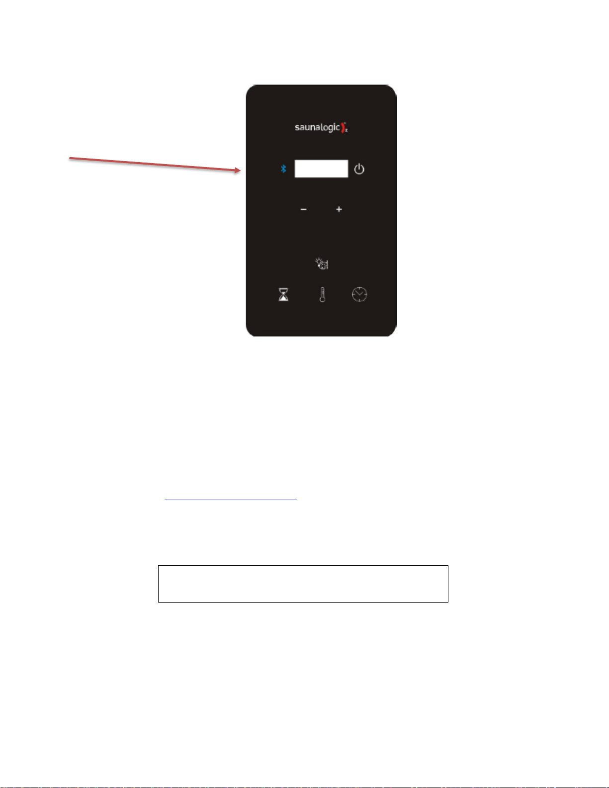
46. Use a flat-blade screwdriver to carefully pry the front glass off the control
body.
Open slot facing up
71-0164 Page 12 4215-139
Rev. 01 09/07/2021
47. Install two of the shorter screws to the control. Place a black plastic wing on the end of each screw. (Longer screws
are not used)
48. Mount control on to wall so the wires are inside the wall. Secure control to wall with the previously installed screws
and wings. Place glass cover on control.
49. Hang heater on front wall. Use the mounting template included inside the heater shipping box to correctly pre-drill the
4 mounting holes.
50. Assemble wood heater guard before installation using the
screws and wooden buttons provided. Use the two spacing
blocks as a guide for installation. Place one block
horizontally on the floor and the other stacked vertically on
top. Install the wood heater guard around the sauna heater
using the 1 1/8” screws provided.
51. Temporarily connect the backrest lights to the back wall.
52. Ensure all electrical connections are installed and
everything is safe.
53. Apply power to the heater. The control will flash for about 15 seconds as it is booting up.
54. Press the room light button to ensure backrest lights turn on.
55. Press the On button on the control and allow heater to run for 15 seconds, then turn off.
56. Put your hands close to the elements (DO NOT TOUCH) to feel if all three elements are heating. Or, have the
electrician verify the correct Amp draw for your heater.
57. Confirm everything is working. After confirmation, do the final installation of the control and install rocks in the
heater.
71-0164 Page 13 4215-139
Rev. 01 09/07/2021
User and installation manual for SL2 Sound Bar (Optional)
This Bluetooth Audio system has been designed exclusively for use with the SL2 and SL2-C sauna control systems. Do
not attempt to connect to any other control system. Record the product serial number, found on the back of the sound bar
in the space designated on the back of this document and save for future reference.
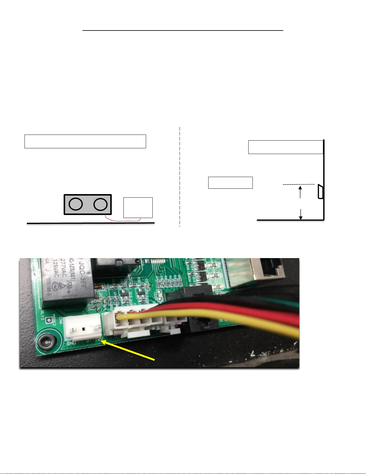
Mounting SL2 Sound Bar
•It is recommended that you mount the sound bar off the sauna floor. Attach the wooden cleat as shown in
Diagram B with the bevel facing up, using the 2” Torx bit screws. The best sound will be achieved if the sound
bar is mounted in the center of the back wall. You may want to experiment with locations before securing the
wall cleat.
•Hang the SL2 sound bar on the wall cleat. (Mating cleat is located on the back of the sound bar.)
•Connect the sound bar power cord to the “CN6” port, located inside the SL2 or SL2-C contactor box.
8” min.
Upper Bench
SL2 CB
BOX
Lower Bench
Diagram A
Diagram B
Upper Bench
Back wall of sauna
CN6 Audio
Power
71-0164 Page 14 4215-139
Rev. 01 09/07/2021
Using your SL2 Sound Bar
•Touch the Bluetooth button on your SL2 or SL2-C control to activate power to the SL2 Sound Bar.
oA confirmation tone will be heard on your sound bar speakers when power is applied.
•Locate “Bluetooth” in your smart device settings. Find and select “TyloHelo Audio”.
oYou will hear a confirmation beep when pairing is complete.
•Open your favorite music source App and use the volume keys on your smart device to adjust volume on the SL2
Sound Bar. All control functions are through your smart device and music App.
WARRANTY
TyloHelo Inc. will warranty the SL2 Sound Bar for a period of one (1) year from date of purchase. Warranty may include
repair or replacement of any/all components, at TyloHelo’s discretion.
Contact TyloHelo Technical Support Team for questions regarding the use of the SL2 Sound Bar or to file a warranty
claim. 1-800-363-0251 or at techsupport@tyloheloinc.com
Date of Purchase: _______________
Place of Purchase: ____________________
Bluetooth Activation
Button
Record Serial Number Here
71-0164 Page 15 4215-139
Rev. 01 09/07/2021
INTERIOR INSTALLATION
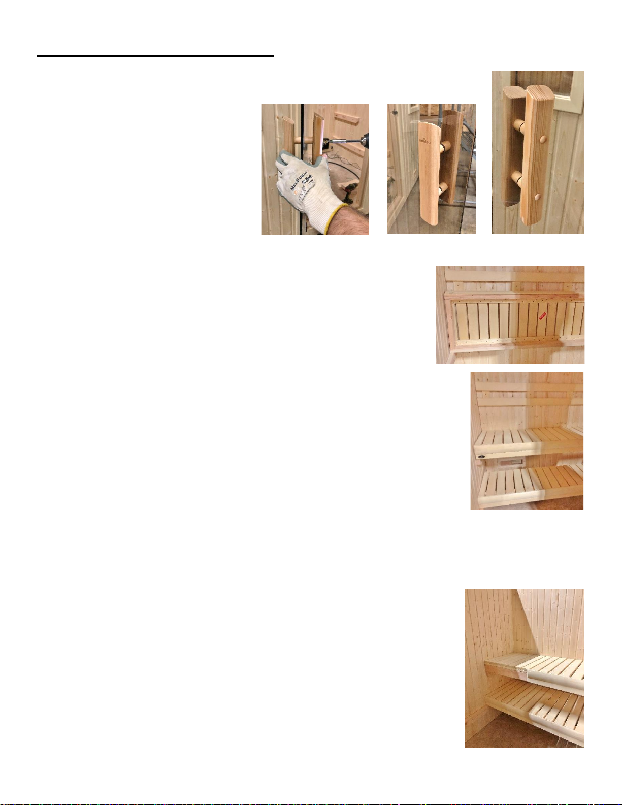
58. Install door handle so the handle with the predrilled holes is inside the room. Secure handle
with two screws provided within the handle package and cover screw heads with wooden
buttons.
The NS 46 and NS 56 bench systems have two benches which span from left to right
walls.
59. Place upper bench on the upper bench supports. Rest the bench upward for easier
installation of the lower bench.
60. Place lower bench on the lower bench supports. Lower upper bench into place.
61. Secure upper bench with two 3” screws through the framework into the backwall and one
3” screw into right and left sidewalls.
Note: Do not secure the lower bench, as it is designed to slide back out of the way for ease of
cleaning.
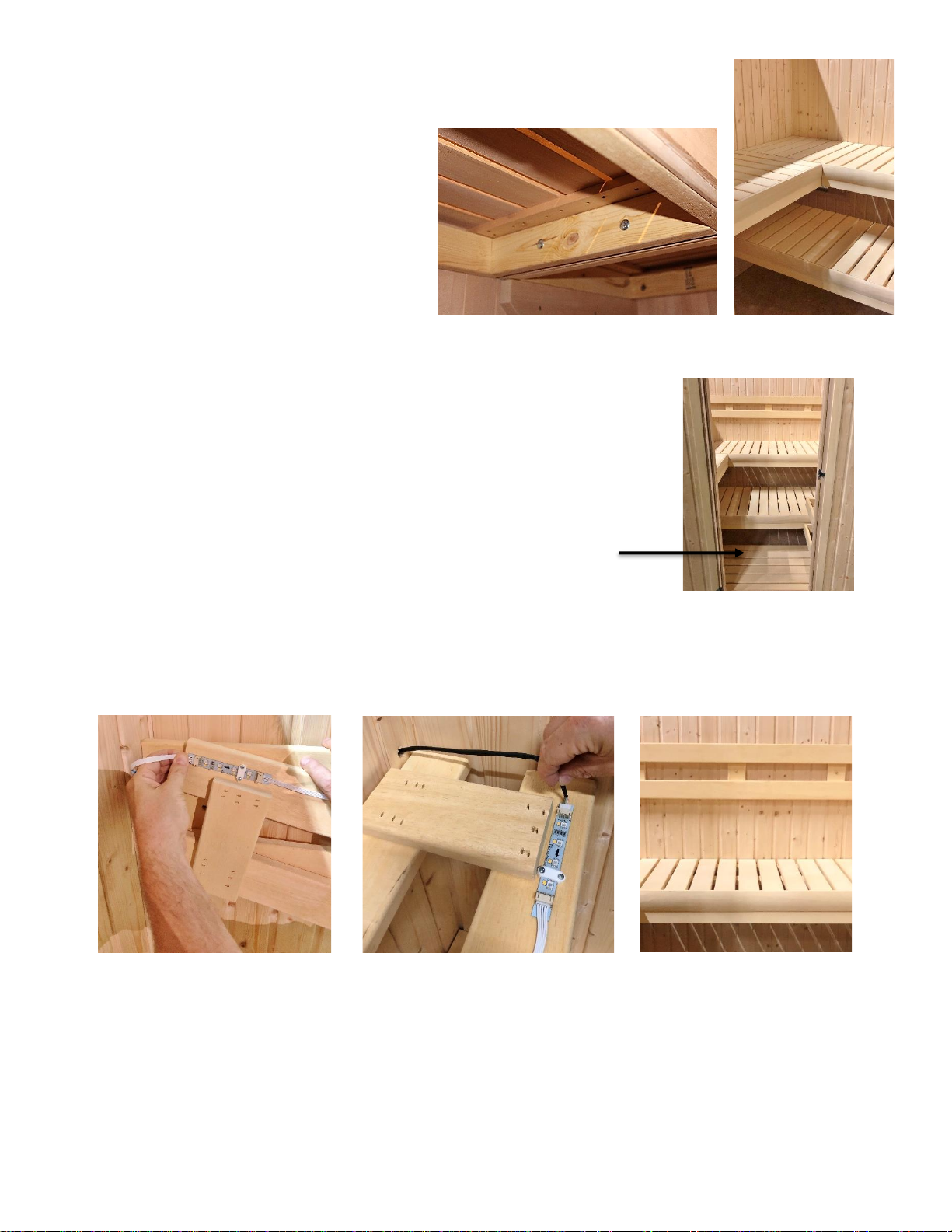
The NS 57 bench system has three benches (Upper Main Bench, Upper Return Bench, Lower Main Bench). The upper
main bench and lower main bench span from left to right walls. The upper return bench butts up to the upper main bench
and spans to the front wall.
62. Place upper main bench on upper bench supports. Rest bench upwards.
63. Place lower main bench on lower bench supports. Lower upper bench into place.
71-0164 Page 16 4215-139
Rev. 01 09/07/2021
64. Install upper return bench to the notch on the upper main bench and the front wall bench
support. Use the 3/8” bit to drill 2 holes where the upper main and upper return benches
meet. Bolt the benches together using the carriage bolts provided.
Note: When aligning the return bench with the
main upper bench, make sure the bench tops are
flush with each other.
65. Place duckboard (floorboard) on floor in front of the lower bench.
66. Connect the wires from the back of the backrest to the wires from the back wall. Install the backrest to the back wall
through the predrilled holes (standard height is 20” from top of bench to top of backrest). Install wooden buttons over
screws.
71-0164 Page 17 4215-139
Rev. 01 09/07/2021
SL2 (SaunaLogic 2) Control Operation
Operating Instructions for Heater
Default settings for temperature are preset to 194°F, the bath time is set to 60
minutes and 0-minute delay to start to heat. These settings are adjustable (as
described below) from 119°F to 194°F. Length of sauna can be set from 0 to
60 minutes. The time delay before start can be up to 24 hours. Any changes
are remembered by the heater for your next bath. Should the heater power be
lost then restored, the settings will return to their default values.
STARTING SAUNA HEATER IMMEDIATELY
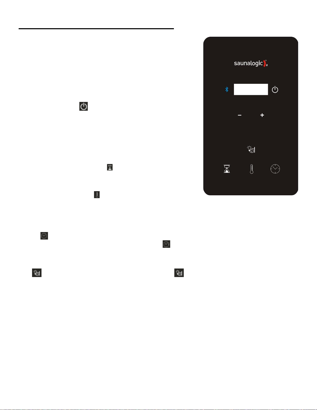
Press the control POWER icon to turn on the sauna control and heater.
The room temperature will be displayed on the control. The heater will turn
on and begin heating the room to current set points. Once the set temperature
is reached inside the room, the control will turn the heater on and off again as
needed to maintain the desired temperature. At the end of the selected time
(60 minutes maximum), the control will turn itself off and the control display
will turn off.
SETTING THE TIME AND TEMPERATURE
To set the sauna length time, press the icon and then press the “"+" or "-"
icons to increase or decrease time for desired setting. The maximum of time is
60 minutes.
To set the temperature, press the and next "+" or "-" icons to increase or
decrease temperature for desired setting. The maximum temperature is 194°F (90°C).
Note: Typical sauna bathing set-point temperature is 150°F to 165°F on the control.
PRE-SET DELAYED START
Press the icon and delay time will appear in the display and will toggle between “dlay” the amount of time remaining.
The maximum of time is 24 hours. If no delay is desired, press icon to toggle off the function.
Operating Instructions for Lighting
Press icon to cycle through lighting options. Press and hold the icon for 3 seconds to turn off the lights. Lights
will turn off automatically 10 minutes after sauna cycle is completed.
-Color sequence –White –Red –Green –Blue –Yellow –Aqua –Purple –Rotation of Colors –Off
Choose the color of choice and then set lighting brightness. The brightness will be on display for 3 seconds. Press the “+”
or “-“ icon to increase or decrease the light setting. Setting options are 25, 50, 75, and 100% light output.
71-0164 Page 18 4215-139
Rev. 01 09/07/2021
AUDIO OPERATION
Audio Power On
•Press icon to toggle On or Off the Bluetooth System.
Note: The control does not have to be active for Sound System to operate.
Pairing
•Refer to your mobile device to pair to the unit.
•The Room device name is TyloHelo Audio
Operation
•All operations are controlled by the mobile device
•Volume is controlled by the mobile device
WARNING
Apple will not warranty your Apple product if used at operating temperatures of 32oF or below and 95oF and above. The
recommended operating temperature is 32oF to 95oF to fall into the warranty. Check with any other device manufactures
for operation temperatures before using the device in the Sauna/IR Room.
USER MAINTENANCE INSTRUCTIONS
Room Instructions for Cleaning:
Perspiration and dirt may absorb into the wood, so periodic cleaning is needed.
Scrubbing the benches and floorboards with a stiff brush and mild detergent is normally
sufficient. Light sanding is another option.
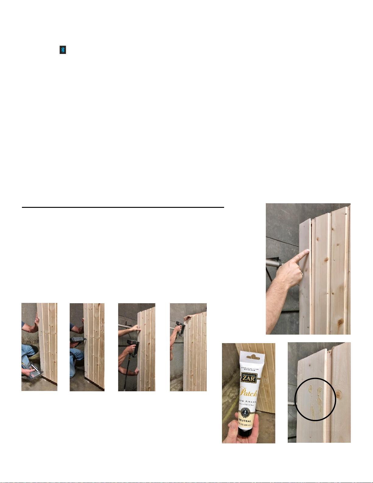
Room Assembly Questions
If corner cap wood is twisted, nail it into the wall panel to secure to room. If it is twisted
at the top, start nailing at the bottom and work up as another person is holding the corner
cap firm against the wall panel. If it is twisted at the bottom, start nailing at the top and
work down.
Trim the excess nail off the corner cap. Apply wood filler to repair
spots. Sand clean so you don’t see the nail heads.

71-0164 Page 19 4215-139
Rev. 01 09/07/2021
TROUBLESHOOTING
Error Codes on SL2 Control
Sn = Means the sensor is not connected to the CB box. Check the connections between sensor and box
HL = Means the Hight Limit switch in sauna heater is not connected to the CB box. Check the connections between
heater and box.
JP = Means a jumper CN 6 is missing from the Main PCA in CB box.
Pre-Heat = Means there is no sensor connected to the CB or the temperature is below 8°F.
Prior to calling, please have the Model, Type Number, and Serial Number from room available.
If you have any questions during the installation of your sauna, please contact your local dealer or our tech support team.
Toll Free: 1-888-780-4427
E-mail: techsupport@tyloheloinc.com
Date of Purchase: _______________________ Place of Purchase: ____________________________
Enjoy Your Sauna!
Follow Finnleo (@finnleosauna) on social media. Tag Finnleo & include #MyFinnleo for a chance to be featured on our
page.
www.finnleo.com
575 East Cokato St., Cokato, MN 55321
Record Serial Number Here
Other manuals for NorthStar Series
2
This manual suits for next models
3
Table of contents
Other Finnleo Plumbing Product manuals

Finnleo
Finnleo Centurion Indoor Series User manual

Finnleo
Finnleo NorthStar Series User manual

Finnleo
Finnleo Euro Outdoor Series User manual

Finnleo
Finnleo Hallmark V3 Series User manual

Finnleo
Finnleo NorthStar Series User manual

Finnleo
Finnleo Hallmark V4H Series User manual

Finnleo
Finnleo Vita II User manual


