Finnleo Euro Outdoor Series User manual

71-0156 Page 1 4215-136
Rev. 03 10/21/2022
Euro Outdoor Series Owner’s Manual
Precautions Before Use
2
Exterior Paint Requirements
3
Receiving Shipment
4
Installation Summary, Base & Wall Panel
5-6
Top Plate
7
Standard Roof
8-9
Metal Roof
10
Interior
12-14
Heater, Wiring, Rocks
14
Commonly Asked Questions / Troubleshooting
15
*Actual sauna may vary from image
displayed

71-0156 Page 2 4215-136
Rev. 03 10/21/2022
Read all instructions carefully before
installation including instructions packaged
separately with the sauna heater. Please leave
all instructions and warranty with the owner.
WARNING: When using electrical sauna
heaters and associated sauna products, basic
precautions must be followed, including the
following:
1. Grounding is required.
2. No electrical receptacle shall be
installed in the sauna room.
3. Be sure rocks are placed in the heater
according to the Heater Installation
and Operation Instructions.
4. Do not tamper with the door or install
a latching or locking system.
Malfunction of which may cause
entrapment inside the heated room.
5. Do not block ventilation openings.
Vents must be kept free of obstruction
so proper airflow is maintained in the
sauna room.
WARNING: The use of alcohol, drugs, or
medication can increase the risk of fatal
hyperthermia.
WARNING: Prolonged exposure to elevated
temperatures is capable of inducing
hyperthermia. Hyperthermia occurs when the
internal temperature of the body reaches
several degrees above the normal body
temperature of 98.6°F. The symptoms of
hyperthermia include an increase in the
normal temperature of the body, dizziness,
lethargy, drowsiness, and fainting. The effects
of hyperthermia include failure to perceive
heat, failure to recognize the need to exit the
room, unawareness of impending hazard,
fetal damage in pregnant women, physical
inability to exit the room and
unconsciousness.
CAUTION FIRE HAZARD: Do not use the sauna
room for drying clothes, bathing suits, etc. Do
not hang towels above the heater or place
any object, other than the rocks supplied, in
the heater. If any darkening of the wall
around the heater is noticed, discontinue
sauna use immediately.

71-0156 Page 3 4215-136
Rev. 03 10/21/2022
Tip: Paint/Stain exterior cove trim prior to installation.
Note: A natural characteristic of wood is to shrink over time. You may need to apply a second coat
of paint or sealer. Follow selected paint or stain manufacture maintenance and reapplication
schedule.
Euro Outdoor Sauna Coating Recommendations
Wood
Species
Product
Brand
Water vs.
Oil
Supplier
Additional Comments
Western
Red
Cedar
Paint
Duration
Water
based
Sherwin Williams
Self-Priming
Emerald
Water
based
Sherwin Williams
Self-Priming
Pittsburgh
Paramount
Water
based
Various
Self-Priming
Stain
Storm
Oil based
Hirshfield’s
Requires “storm”
primer. Variations of
tones/colors
Sikkens Cetol Log
and Siding
Oil based
Various
Transparent
•WARNING!
The raw wood exterior of this sauna MUST be sealed with an
approved exterior coating immediately! Exposure to rain in
the “raw” state can permanently damage the wood and void
your warranty!
4126-126 Rev A

71-0156 Page 4 4215-136
Rev. 03 10/21/2022
Receiving Shipment
Upon delivery remove shrink wrapping material and inspect all boxes and
exposed components for damages during shipping. If any damage is
found, you must notify the delivering carrier immediately.
A few minutes with the following instructions will ensure quick and
proper assembly, and many years of enjoyment and relaxation. By
reviewing all the instruction steps ahead of time, you will have a
better feel for the entire process.
Your sauna package will arrive on a stretch-wrapped pallet including a
stack of prebuilt panels, benches, and boxes with the heater and
accessories.
Hardware Package
▪Bag of 1 1/2” screws
▪Bag of 3” Screws
▪Torx Bit
▪2 Carriage Bolts w/ Washer and nut.
*Screws are specially coated to not react with cedar or pressure treated wood.
Tools Required
▪Hammer or brad nailer
▪Handsaw or miter box (trim molding installation)
▪Cordless Drill
▪Tape measure
▪Square
▪Level
▪3/8” wood bit (if sauna has an L-bench)
▪Torx bit (provided)
▪Shims
▪Phillips screwdriver
▪Finishing Nails
▪100% Silicone caulking

71-0156 Page 5 4215-136
Rev. 03 10/21/2022
Integral Floor
INSTALLATION OF SAUNA ROOM
All wall panels will be numbered at the top and should be visible from the
interior of the room. These numbers will coincide with the numbers on
the base frame. NOTE: The tongue and groove on the panels will always
face the same direction
•EACH PANEL IS HEAVY.USE CAUTION TO AVOID INJURY WHEN INSTALLING,
ESPECIALLY THE ROOF PANELS.
•TWO ADULTS ARE REQUIRED FOR THE INSTALLATION OF SAUNA ROOM.
Base Installation
1. Position the base frame or Integral floor in the desired location on
a level surface. The largest number on the base frame is the
standard door location. The stamped numbers on the base frame
should be readable from inside of the room.
a. Standard base (rooms larger than 5x7): Fasten the corners
of the base frame using one 3” screw at each corner in the
predrilled holes. Predrilled holes are purposely made at an
angle.
b. Integral Floor (rooms less than 5x7): The base frame will be
built into the integral floor.
2. The base rail is numbered to correspond with the panels. Number
1 should be to the right of the door, couting up as you move
counter clockwise around the base.
3. Using a level and measuring tape, confirm the base frame is square
by measuring corner to corner. The dimensions should be the
same when the base is square. Shim where needed to level the
base.
Wall Panel Installation
4. Starting in a corner place the panel on the outer edge of the
corresponding floor panel. Slide the panel along the base frame
until framework is flush with the outside of the base frame.
NOTE: To help prevent rain, snow, and moisture, use silicone caulk
in between the base rail and walls as well as in between wall panel.
5. Hold the first panel in place and carefully lower the perpendicular
side wall corner panel into the base, starting at an angle and sliding
it into place. Slide it tight into the corner so framework is tight up
against the framework of the other panel.

71-0156 Page 6 4215-136
Rev. 03 10/21/2022
NOTE: The 4x6,5x6, 6x12 rooms have a one-piece side wall system,
and the 4x5, 5x7, 7x10 rooms have a two-piece side wall system.
The process is the same for the one or two-piece systems.
NOTE: For ease of installing the panels, tilt the top of each panel
back to get the tongue and groove alignment started. Then tilt
forward for an easy fit.
6. Secure the 2 corner wall panels with three 3” Torq screws
(provided). Install one screw on the top of the wall, one in the
middle, and one on the bottom. Ensure the tongue and groove
wall boards are tight together at the interior corner of the sauna
and the corner is flush on the outside edge when screws are
installed.
7. Ensure that the two corner wall panels are flush for the entire
length (base to top) and locate the pre-drilled holes and use the
supplied 3” screws to secure the two panels together.
8. Continue to install each wall panel with the corresponding base
number staring from your initial corner and working around the
room.
9. Make sure that the wall panels are flush at the top and seated into
place at the bottom. Ensure the tongue and groove are fully
engaged between each panel.
10. First ensure tongue and groove are fully engaged. Then secure the
2 back wall panels together with a 3” screw where the panels meet
on top.
11. Continue installing the next panel in the number series, being
careful not to damage the tongue & groove pieces of the panels.
Remember to angle the wall panels and then slide them into place
so that the length of the tongue is seated firmly and evenly into
the groove.
NOTE: A rubber mallet or wood block and standard hammer can
be used to make sure that the bottoms of each panel are even
with the corners of the base frame/floor perimeter. Be careful not
to damage the panels when using this technique.

71-0156 Page 7 4215-136
Rev. 03 10/21/2022
12. Secure the side wall to the back wall panel with (3) 3” Torq screws.
Install one screw on the top of the wall, one in the middle, and one
on the bottom.
13. Install the remaining wall panel up to the door panel. You will
install the door panel next to the right front wall panel before you
install the final wall panel.
14. Secure left front wall panel to the left side
wall with three 3” Torq screws. Ensure the
tongue and groove are tight at the interior
corner when screws are installed.
Top Plate Installation
15. After installing the wall panels, install the 1” top plate. This top
plate aligns and locks the top of the wall panels together.
Note: Before installing top plates, ensure all panels are fully
connected on top and on the corners.
16. Install back top plate first. Matching top plate
with the corresponding wall panels number.
Install notched ends facing up.
17. Install the left and right wall top plates notched end facing down.
So, they fit into the notches of the corresponding top plate.
18. Firmly press down (use a hammer if needed) until top plates rest
on the framework of the wall panels.
19. The top of the plate should be flush with the top of the interior
tongue and groove.
20. Secure top plates using the 2” Torque screws. Install one screw in
each corner and one screw in the center of each wall.
21. Install ½” self-adhesive foam weather stripping on
the top plates. Adhesive side down to the top plate.
22. Install corner caps to each corresponding wall panel
make sure corner cap is flush with base of wall.
Secure using Brad nails or finishing nails (not
supplied),

71-0156 Page 8 4215-136
Rev. 03 10/21/2022
23. Install a 3” Torq screw into each access opening to secure the walls
to the base plate and floor
24. Install an access board into each opening. Secure with Brad nails.
Note: Electrical access or other labeled access boards are
intentionally left uninstalled. Do not install panels until electrical
components have been installed and assessed by a licensed
electrician.
Roof Panel Installation
Note: Number of roofing panels will vary
depending on the roof size.
25. Using two people, carry the first roof panel over to the sauna,
carefully feed the roof panel into place without scratching the
panels. When in position, it will rest on the top plate.
26. The guide strip will align exterior of the high side wall panel until
final placement is set and secured.
27. Make sure the first panel is aligned using the guide strip at the
front end of the panel. Continue placing remaining panels, make
sure all panels are centered with even overhang. Approximately 8
inches overhang on right and left side.
28. The tongue and groove of the inner ceiling should fit together
snug. *A rubber malett may be needed to aceive a snug fit.
29. Secure roof panels together using a 3” Torq screw. Drive screw in
at a 45-degree angle connecting the two panels together at the
seam to make one large panel. Complete this step at both front
and back of roof panels.

71-0156 Page 9 4215-136
Rev. 03 10/21/2022
30. Using the 5-1/2” Torq screws, screw through the roof panel to
secure to the top of the walls. Secure the roof panel at the front of
the sauna and ensure the side overhang in the back of the sauna is
the same as the front. Secure roof to back wall and then side walls.
31. Once the roof panels are secured, remove the guide strips at the
front so trim can be installed later.
32. Nail fascia trim to the exterior edge of roof starting with the back
edge. Next the two side edges, and lastly the front edge. The fascia
top should be flush with the top of the roof panel.
33. Install eve trim under the overhanging fascia on front and back of
sauna only. The front side eve trim is flush to the left and right-side
fascia. The back trim is flush to the left and right-side fascia.
34. Install the left and right-side eve trim so it is flush to the back
side trim and front side trim.
35. Install exterior cove trim to the back wall so it is flush to the left
and right edges of the wall.
36. Install exterior cove trim to left and right-side walls so it is flush
to back side cove and the edge of the front wall.
37. Install exterior cove trim to front wall so it lays flush to left and
right-side cove.
38. Install the roofing felt on the roof panel using a roofing stapler.
Start from the low side of the room, working towards the high
side. Overlap the paper a minimum of 2”.
Trim roofing felt to be flush with the edges of
the roof panels.

71-0156 Page 10 4215-136
Rev. 03 10/21/2022
Optional Metal Roof Installation
Note: Optional Gray metal roofing can be purchased for
rooms up to 5x7 at time of room order. You may elect to
purchase your own metal or other smooth continuous
exterior roofing material. Instructions will vary
dependent on your choice.
39. Cut metal drip edge to the length of the roof and install
under roofing felt to the back side of roof so the side
with three grooves is on top of roof. Secure to roof with
roofing nails or staples.
40. Lay out the metal roofing sheets on a flat surface to
determine the amount of overlap needed to match the
width of the roof. This will provide the starting point for
roof placement.
Note: Determines the distance from the edge to the
start of the metal roofing sheets
41. Begin to install the metal roofing based of your
predetermined lay out of metal roofing sheets.
Center the metal roofing over the room. The left
overhang should be equal to the right overhang.
Check three points on each side to ensure the
distances are equal.
42. Secure the high side with roofing screws.
Note: Do not fully secure roofing you will need to
be able to lift the low side to install foam.
43. Insert foam between metal roofing and drip edge
to prevent insects from getting under roofing.
44. Secure metal roofing with one row of screws at the back of roof at
every other rib and another row of screws across the middle of
roof at every other rib.
Note: Predrilling the metal with a 1/8” drill bit is suggested for ease
in installation.

71-0156 Page 11 4215-136
Rev. 03 10/21/2022
45. Mark and cut the left and right-side flashing
flush with front edge of roof. This cut should be
made at a slight angle.
46. Secure left and right-side flashing to fascia with
sheet metal/roofing screws.
47. Mark and cut the front ridge with a ¼” of overhang on each side.
48. Install front flashing to the roof so there is ¼” of overhang on each
side. Secure on top with sheet meal/roofing screws, one 5-1/2”
from each edge and the remaining two centered in between.
Secure to fascia with roofing screws.
49. Before screwing down the front flashing, insert the seal on top of
roofing metal and underneath the front flashing.
Note: Suggested to caulk seams at flashing joints.

71-0156 Page 12 4215-136
Rev. 03 10/21/2022
Interior Cove Molding Installation
50. Using #4 finishing nails (Pneumatic nailer preferred), nail the cove
molding to the interior walls.
51. Secure the molding to the walls nailing it through the bottom &
into the ceiling to help keep it in place.
Bench Installation
In most cases the bench supports are pre-installed. If not, the interior
walls have been marked and labeled at the heights you should attach the
bench supports. Standard top bench support is 30” and lower bench
support is 12”. These are the heights off the floor to the top edge of the
bench supports, not the top of the benches.
If not pre-installed follow these steps:
oLocate the bench supports. Install starting with the top
bench support first.
oPosition the bench supports tight into corner. Making
sure they are level, use 3” screws and pre-drilled holes
to secure the bench supports to the walls. Be sure to
install screws in all the pre-drilled holes.
NOTE: One side of the bench is capped, while the others have
exposed framing. Benches should be installed with the capped side
facing forward
Note: The 4x5, 4x6, and 5x6 bench systems have two benches
which span from left to right walls.
52. Starting with the lower bench and sliding into place against the
back wall.
53. Place upper bench on upper bench supports.
54. Secure upper bench with two 3” screws through the framework
into the backwall and one 3” screw into right and left sidewalls.
Note: Secure the lower bench only in rooms with a return bench,
Lower benches with no return bench are designed to slide back
out of the way for ease of cleaning.

71-0156 Page 13 4215-136
Rev. 03 10/21/2022
Room with Return (“L-shaped”) Bench
Note: The 5 x 7 room bench system has three benches (Upper Main
Bench, Upper Return Bench, Lower Main Bench). The upper main
bench and lower main bench
span from left to right walls. The upper return bench butts up to the
upper main bench and spans to the front wall.
55. Install upper return bench to the notch on the upper main bench
and the front wall bench support. Use the 3/8” bit to drill 2 holes
where the upper main and upper return benches meet. Bolt the
benches together using the carriage bolts provided.
Note: When aligning the return bench with the main upper bench,
make sure the bench tops are flush with each other.
Backrest Installation
56. Locate the backrest and remove the backrest mounting hardware
from the backside of the backrest. The longest backrest will be
installed on the back wall. If you have a return bench the other
backrest will be above the return bench.
57. Place backrest finished side down on the upper bench with the LED
light strip closest to the bench front. Next, connect the low-voltage
power cable from the back wall to the LED lighting strip end.
Connect the 12” LED jumper to the other end of the LED strips.
This will be used to connect the left backrest.
NOTE: Cut 2 pieces of wood to 8 3/8” to
use as a gauge block. Position them on the
upper bench to make installation of the
backrest easier.
58. Measure 20” from the top of the bench to
the top of the backrest. Making sure
backrest is level, fasten it to the wall through the predrilled holes,
using 2” screws (provided).
Note: If using gauge block carefully remove. Wood plugs are
provided to cover the exposed screw head.
Door Handle
59. Install door handle so the handle with the predrilled holes is in the
inside of room. Secure handle with two screws provided within the
handle package and cover screw heads with wooden buttons.
Sauna Heater
Installation

71-0156 Page 14 4215-136
Rev. 03 10/21/2022
*Defer to heater manual for specific instructions.
60. A licensed electrician should wire the heater according to the
specifications provided with the heater. One of the wall panels has
a removable board to allow for wiring access to the heater. This
tongue and groove board is in the trim package. After the wiring,
attach the board with the brad nailer.
Wiring
*Defer to heater manual for specific instructions.
61. Depending on your heater and control selection for the sauna, you
may or may not need a low voltage connection box for the lights.
When using a SaunaLogic2 control, the lights are hooked up inside
the regular contactor box. Other heaters such as the Designer,
Vena and others may need this low voltage box for lighting hook-
up.
Rock Placement (Very Important)
*Defer to heater manual for specific instructions.
62. Rinse the rocks before placement in the sauna heater. Place the
smaller and flatter rocks around the outside of the rock
compartment and the larger rocks in the center. This allows good
air transfer through the heater. Do not try to force all the rocks in,
it is important to have space between the rocks.
Duck Board
63. Place duckboard (floorboard) on floor in front of the lower bench.

71-0156 Page 15 4215-136
Rev. 03 10/21/2022
WARNING!
The exterior of your Euro outdoor sauna requires prime & paint or stain within a few days
of installation, and before being exposed to rain or snow. DO NOT paint or stain the
interior. See page 3 for recommendations.
COMMONLY ASKED QUESTIONS
CLEANING
It is a good practice to always place a clean towel on the seating surfaces during sauna use and wipe
surfaces dry when done bathing. However, perspiration and dirt may absorb into the wood, so
periodic cleaning is needed. Scrubbing the benches and floorboards with a stiff brush and mild
detergent is normally sufficient. For heavily soiled or stained wood, a light sanding with 220 grit
sandpaper is another option.
Light cleaning and dusting with a damp microfiber cloth can be used on all surfaces.
STAINING OR PAINTING THE INTERIOR
You should never use stains or paints on the interior of a sauna! These products will off-gas during
the heating cycle and could be harmful to your health.
The only approved product to use on the interior of your sauna is 100% pure paraffin oil. Available
from your dealer or Sauna360, pure paraffin oil will add a breathable, colorless, and odorless layer
of protection against moisture absorption on the wood surfaces. Depending on use, the protection
can last several months or longer before re-application is needed. (Note: use of Paraffin oil on soft
woods like cedar may darken the color of the wood)
STAINING OR PAINTING THE EXTERIOR
All outdoor sauna’s must be protected from the elements as soon as the sauna is built! Reference
your installation guide or contact Sauna360 for a list of recommended products. Failure to protect
the sauna can result in damage to the exterior of the sauna and may void your warranty.
REPAIRING NAIL HOLES AND CRACKS
Any decent quality wood filler that matches your wood species can be
used to fill any small nail holes or even smaller cracks. Apply filler,
allow to dry then use a 220-grit sandpaper to smooth the surface.

71-0156 Page 16 4215-136
Rev. 03 10/21/2022
If you have any questions during the installation of your sauna, please contact your local dealer.
Date of Purchase: _______________________
Place of Purchase: ____________________________
Enjoy Your Sauna!
Follow Finnleo (@finnleosauna) on social media. Tag Finnleo & include #MyFinnleo for a chance to
be featured on our page.
www.finnleo.com • 575 East Cokato St., Cokato, MN 55321
Record Serial Number Here
Link to Finnleo Manuals
Other Finnleo Plumbing Product manuals

Finnleo
Finnleo NorthStar Series User manual

Finnleo
Finnleo Vita II User manual

Finnleo
Finnleo NorthStar Series User manual

Finnleo
Finnleo NorthStar Series User manual
Finnleo
Finnleo Centurion Indoor Series User manual

Finnleo
Finnleo Hallmark V4H Series User manual
Finnleo
Finnleo Hallmark V3 Series User manual
Popular Plumbing Product manuals by other brands
Kohler
Kohler 1152813-A2-A Installation
Signature Hardware
Signature Hardware KIRANA 949634 quick start guide
Toto
Toto REI S TX492SRS quick start guide
Kohler
Kohler PATIO Series installation instructions
Moen
Moen 6202 Series Specifications
Hans Grohe
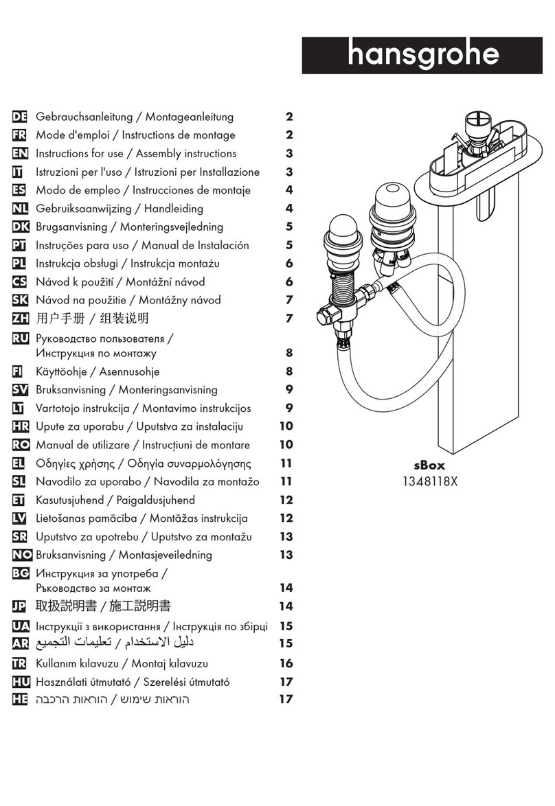
Hans Grohe sBox 1348118 Series Instructions for use/assembly instructions
