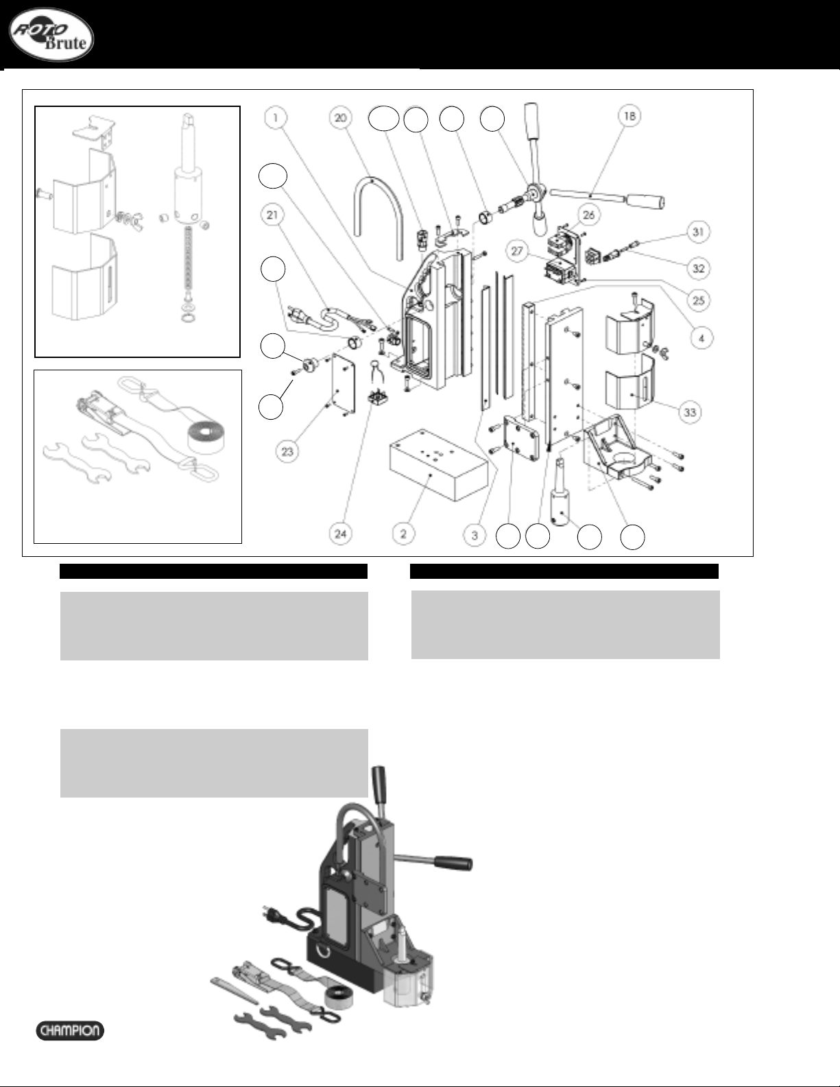
INCLUDED WITH EVERY RB45
Carrying case, safety strap, RB433 #2MT arbor, operating handles, cutting fluid, safety guard,
drify key and hex keys.
EEaarraannddeeyyeepprrootteeccttiioonnMMUUSSTTbbeewwoorrnndduurriinnggooppeerraattiioonnoofftthhiisseeqquuiippmmeenntt..DDooNNOOTT
ttoouucchhtthheeccuutttteerrwwhhiilleeiittiissiinnmmoottiioonn..AAllwwaayyssffoolllloowwtthheePPeerrssoonnaallPPrrootteeccttiioonn
EEqquuiippmmeenntt((PPPPEE))rreeccoommmmeennddaattiioonnsswwhhiilleeooppeerraattiinnggtthhiissttooooll..
TThhiissmmaacchhiinneeiissddeessiiggnneeddssppeecciiffiiccaallllyyffoorrddrriilllliinngghhoolleessiinnsstteeeelluussiinnggaannnnuullaarr
ccuutttteerrssoorrwwiitthhttwwiissttddrriillllsswwhheennuussiinnggtthheeooppttiioonnaallddrriillllcchhuucckk..WWeerreeccoommmmeenndd
CChhaammppiioonn®®RRoottoobbrruuttee™™aannnnuullaarrccuutttteerrss..PPlleeaasseeccoonnssuullttyyoouurrCChhaammppiioonnaauutthhoorriizzeedd
ddiissttrriibbuuttoorrffoorraaccoommpplleetteerraannggeeooffssiizzeess..
DDOONNOOTTmmooddiiffyyaanndd//oorruusseeyyoouurrRRoottoobbrruuttee™™MMaaggnneettiiccDDrriillllPPrreessssffoorraannyy
aapppplliiccaattiioonnootthheerrtthhaann,,ffoorrwwhhiicchhiittiissiinntteennddeedd..
SAFETY
Be sure to read and follow these important safety instructions:
When using your RB45 MightiBrute, be sure to follow these important safety precautions:
1. Before operating the machine, check supply voltage and general conditions, i.e.
cable/cord damage. A machine with damaged cable must be returned or repaired prior to
use.
2. Always use the safety strap in all drilling applications.
4. Since cutting tools can shatter, eye and head protection should be worn
at all times.
5. After use, clean machine and cutters and keep in the case provided.
6. Store when not in use in a dry environment.
7. Always provide a method of catching slug, where the ejected slug may cause injury (slug
ejects at end of cut).
8. Should the cutter jam in the work-piece, stop the machine immediately. Isolate the
machine at the main supply. Loosen the cutter by rotating the arbor. Do not attempt to free
cutter by starting and stopping the motor.
9. Always use the safety guard provided.
Electrical Safety
Grounded tools must be plugged into an outlet properly installed and grounded in
accordance with all codes and ordinances. Never remove the grounding prong or modify the
plug in any way.
Do not use any adapter plugs. Check with a qualified electrician if you are in doubt as to
whether the outlet is properly grounded. If the tools should electrically malfunction or break-
down, grounding provides a low resistance path to carry electricity away from the user.
Never use the cord to carry the tools or pull the plug from an outlet. Replace damaged cords
immediately.
When operating a power tool outside, use an outdoor extension cord marked “W-A” or “W”.
These cords are rated for outdoor use and reduce the risk of electric shock. Minimum gauge
external cord should be 12/3.
Use the RB-32 with 110 A/C voltage only. Not for use with generators, welders or any dc
power source. Do not use on any surface where welding is taking place.
Personal Safety
Stay alert, watch what you are doing and use common sense when operating a power tool.
Do not use tool while tired or under the influence of drugs, alcohol, or medication.
Do not wear loose clothing or jewelry. Avoid accidental starting. Be sure switch is off before
plugging in. Carrying tools with your finger on the switch or plugging in tools that have the
switch on invites accidents.
Remove adjusting keys before turning the tool on.
Do not overreach. Keep proper footing and balance at all times.
Safety equipment (eye protection, dust mask, nonskid safety shoes, hard hat, hearing
protection) should be used for appropriate conditions.
RB45
IMPORTANT
Please read these operating and safety instructions carefully and completely. For your own safety, before using this equipment check that the voltage
is correct and that all handles and parts are firmly secured. If you are uncertain about any aspect of using this equipment, contact your distributor.
PLEASE KEEP THESE INSTRUCTIONS
Tool Use and Care
Use clamps or other practical ways to secure and support the work-piece to
a stable platform.
Do not force tool. Use the correct tool for the application.
Disconnect the plug from the power source before making any adjustments, changing
accessories, or storing the tool.
Storeidle tools out of reach of children and other untrained persons.
Maintain tools with care. Keep cutting tools sharp and clean.
Check for misalignment or binding of moving parts, breakage of parts and any other
condition that may affect the tool’s operation. If damaged, have the tool serviced
before using.
Service
Tool service must be performed only by qualified and authorized personnel, or
warranty is voided.
When servicing a tool, use only original replacement parts. Use of unauthorized parts
will void the warranty,
Use of unauthorized parts or failure to follow maintenance instructions may create a
risk of electric shock or injury.
Magnetic Drill Safety
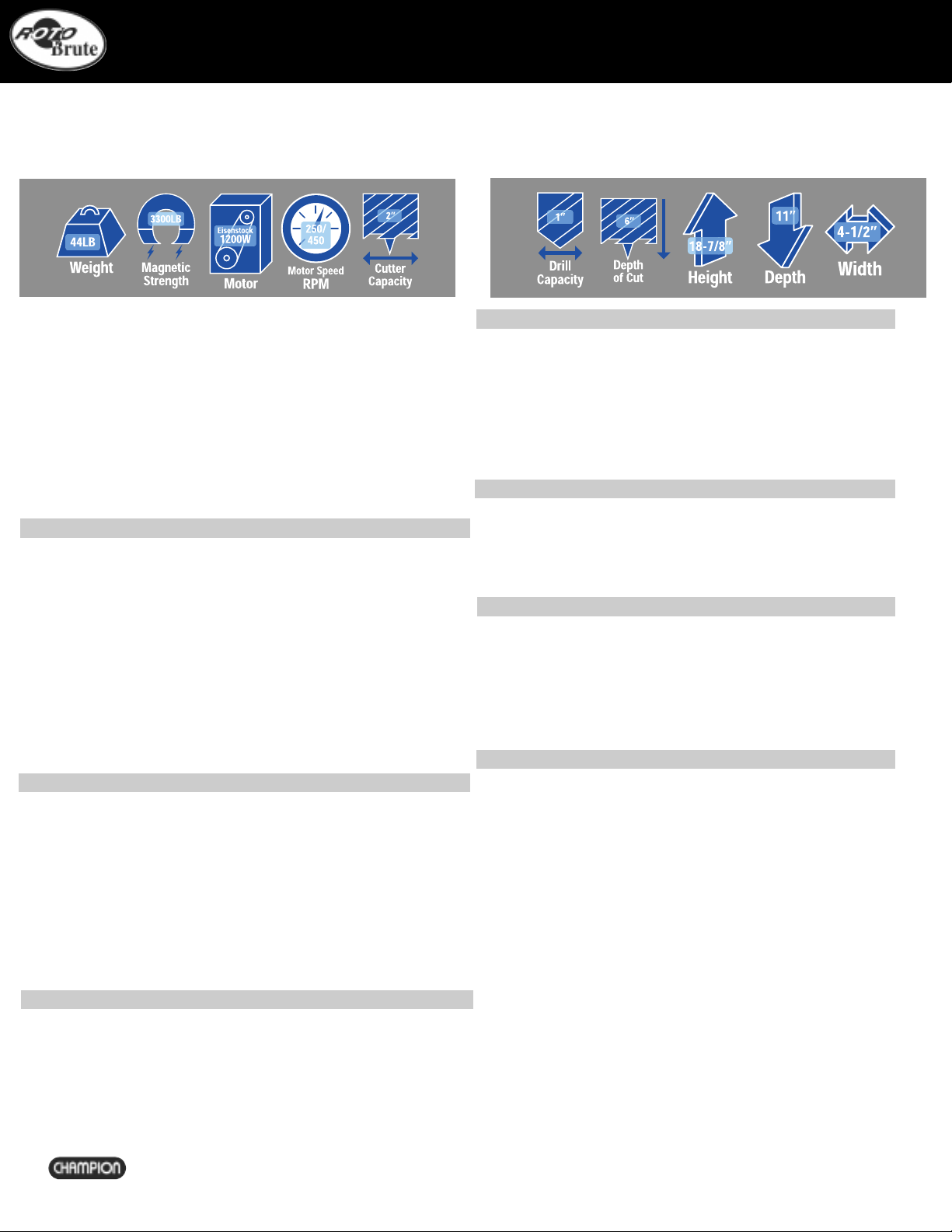
The drill’s magnetic adhesion depends on the thickness of the work-piece. 1/2”
(13mm) is the minimum thickness for safe operation. Keep the magnet clean of metal
chips and other dirt and debris. These will seriously reduce the magnetic adhesion.
The drill must be operated on its own electrical outlet. Always use the supplied safety
strap or chain. An electrical overload can result in loss of adhesion.
CAUTION: The slug ejects at end of cut and is very hot.
WARNING:Do not attempt to drill a work-piece, which is thicker than the maximum
cutting depth of the cutter being used. Never exceed 2” cutter diameter.
Maintenance and Troubleshooting
Keep the drill press and the cord clean. In case of electrical or mechanical
malfunction, immediately switch off the tool and disconnect the plug. Excessive
sparking generally indicates the presence of dirt in the motor or worn out carbon
brushes. Periodically check brushes for wear and replace when they reach 1/4”
(6mm). Also check that the machine is well lubricated.
For all other service and maintenance, please contact a Champion® authorized
service center.
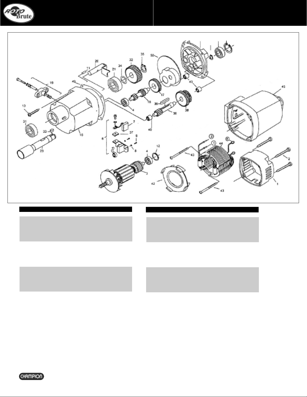
COMPONENTS & SAFETY
2
MIGHTIBRUTE